EP0573647B1 - Krankenhausbett - Google Patents
Krankenhausbett Download PDFInfo
- Publication number
- EP0573647B1 EP0573647B1 EP93903397A EP93903397A EP0573647B1 EP 0573647 B1 EP0573647 B1 EP 0573647B1 EP 93903397 A EP93903397 A EP 93903397A EP 93903397 A EP93903397 A EP 93903397A EP 0573647 B1 EP0573647 B1 EP 0573647B1
- Authority
- EP
- European Patent Office
- Prior art keywords
- drive
- plates
- hospital bed
- bed apparatus
- relative
- Prior art date
- Legal status (The legal status is an assumption and is not a legal conclusion. Google has not performed a legal analysis and makes no representation as to the accuracy of the status listed.)
- Expired - Lifetime
Links
- 230000007246 mechanism Effects 0.000 claims description 21
- 230000004323 axial length Effects 0.000 claims description 8
- 230000002441 reversible effect Effects 0.000 claims description 5
- 230000000694 effects Effects 0.000 claims description 3
- 230000008878 coupling Effects 0.000 claims 2
- 238000010168 coupling process Methods 0.000 claims 2
- 238000005859 coupling reaction Methods 0.000 claims 2
- 239000002184 metal Substances 0.000 description 10
- 125000006850 spacer group Chemical group 0.000 description 4
- 239000000463 material Substances 0.000 description 3
- NJPPVKZQTLUDBO-UHFFFAOYSA-N novaluron Chemical compound C1=C(Cl)C(OC(F)(F)C(OC(F)(F)F)F)=CC=C1NC(=O)NC(=O)C1=C(F)C=CC=C1F NJPPVKZQTLUDBO-UHFFFAOYSA-N 0.000 description 3
- 241000272201 Columbiformes Species 0.000 description 1
- 239000004809 Teflon Substances 0.000 description 1
- 229920006362 Teflon® Polymers 0.000 description 1
- 239000011324 bead Substances 0.000 description 1
- 230000002860 competitive effect Effects 0.000 description 1
- 238000010276 construction Methods 0.000 description 1
- 210000003127 knee Anatomy 0.000 description 1
- 238000012986 modification Methods 0.000 description 1
- 230000004048 modification Effects 0.000 description 1
- 230000002093 peripheral effect Effects 0.000 description 1
- -1 polytetrafluoroethylene Polymers 0.000 description 1
- 229920001343 polytetrafluoroethylene Polymers 0.000 description 1
- 239000004810 polytetrafluoroethylene Substances 0.000 description 1
- 230000008707 rearrangement Effects 0.000 description 1
- 238000003466 welding Methods 0.000 description 1
Images

Classifications
-
- A—HUMAN NECESSITIES
- A61—MEDICAL OR VETERINARY SCIENCE; HYGIENE
- A61G—TRANSPORT, PERSONAL CONVEYANCES, OR ACCOMMODATION SPECIALLY ADAPTED FOR PATIENTS OR DISABLED PERSONS; OPERATING TABLES OR CHAIRS; CHAIRS FOR DENTISTRY; FUNERAL DEVICES
- A61G7/00—Beds specially adapted for nursing; Devices for lifting patients or disabled persons
- A61G7/002—Beds specially adapted for nursing; Devices for lifting patients or disabled persons having adjustable mattress frame
- A61G7/012—Beds specially adapted for nursing; Devices for lifting patients or disabled persons having adjustable mattress frame raising or lowering of the whole mattress frame
Definitions
- the present invention relates to a mechanism for moving a movable part of a hospital bed and, more particularly, to such a mechanism which moves a patient support portion of the bed vertically with respect to a base and which has a threaded member rotatably driven by a motor and operatively engaging a nut.
- the lower end of the hydraulic cylinder must be mounted relatively close to the floor, which increases the chance it may fail to clear an obstruction when the mobile bed is being moved, resulting in possible damage to the hydraulic cylinder and/or a need to manually lift the bed over the obstruction.
- the patient support litter is sometimes supported on the base by a scissors mechanism, which may be driven by a electric drive mechanism or by a single small hydraulic cylinder.
- the scissors mechanism has a number of potential points at which a finger or other body part could be caught and pinched, which can present a safety problem.
- scissors mechanisms tend to be relatively complex and therefore expensive.
- the vertical space required by a scissors mechanism between a patient support litter and a base tends to be sufficiently large that it is difficult to achieve a design in which the patient support litter can move to a relatively low position.
- Beds often have other movable parts, such as a movable knee support section of a patient support assembly. Arrangements of this type are usually driven by an electric motor, and the most common approach is to fixedly support on the bed frame an electric motor having an elongate rotatable shaft which is threaded, to support a nut on the shaft for movement therealong relative to the frame, and to use a link mechanism to operationally couple the nut to the part to be moved.
- DE-C-352059 on which the preamble of claim 1 is based, discloses a height-adjustable patient support table for patients being X-rayed, the table having the features of the hospital bed defined in the pre-characterising part of claim 1.
- the table has a lift mechanism at each corner and all four lift mechanisms are interconnected by a common chain and sprocket drive to a manually operated crank handle for adjusting the height of the patient support.
- the construction of the individual double-screw lift stages is also known from lifting jacks for automobiles as disclosed for example in US patent specifications Nos 1,565,878; 1,874,357; 1,874,772; 1,906,365 and 4,609,179.
- a hospital stretcher having a single-lift screw mechanism at each end and bevel gearing connecting both lift mechanisms to a common operating crank handle is known from US-A-2,127,309.
- Height-adjustable beds and stretchers having a pair of single-lift mechanisms at each end are known from US-A-2,522,759 and 3,253,284, each pair being connectible selectively to a common crank handle.
- a hospital bed according to the invention is defined in claim 1.
- FIG 1 is a side view of a mobile hospital bed or stretcher 10.
- the bed 10 has a base 12 movably supported in a conventional manner on several casters 13, and has a conventional patient support litter 16 vertically movably supported on the base 12 by two spaced pedestals 17 and 18.
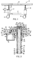
- the pedestal 18 includes two laterally spaced screw lift mechanisms, one of which is visible in Figure 1, and the pedestal 17 includes a single screw lift mechanism which is shown in detail in Figure 2 and is described in detail below. All of the screw lift mechanisms in the pedestals 17 and 18 are substantially identical, and therefore only the screw lift mechanism in the pedestal of Figure 17 is described in detail.
- the patient support litter 16 has secured to the underside thereof a laterally extending horizontal plate 21.
- the base 12 has two laterally spaced upward projections 23, one of which is visible in Figure 1, and a rectangular metal support plate 24 extends between and is secured to the upper ends of the portions 23.
- the plate 24 has in it a rectangular opening 27, and a rectangular metal bottom plate 31 is provided on the plate 24 with its peripheral edge portions supported on top of the plate 24 and its central portion extending across the opening 27 so as to cover the opening 27.
- a cylindrical metal guide portion 32 projects downwardly from the underside of the plate 31, and a cylindrical opening 33 extends concentrically and vertically through the cylindrical guide portion 32 and plate 31.
- annular recess 36 having a diameter greater than that of the opening 33
- annular nut 37 having a helical internal thread is disposed in the annular recess 36.
- the thread on nut 37 projects radially inwardly into the opening 33 from a cylindrical surface on the nut which has a diameter at least as large as the diameter of opening 33.
- metal spacer blocks 41 and 42 are provided on top of the plate 31 at opposite ends thereof, and a metal top plate 43 extends between and has its ends supported on top of the spacer blocks 41 and 42.
- Several bolts 46 each extend through aligned openings in the top plate 43, spacer block 41 or 42, bottom plate 31 and support plate 24, and each threadedly engage a nut 47 so as to fixedly secure the plates and spacer block together.
- the top plate 43 has a cylindrical metal guide portion 51 projecting upwardly from the upper side thereof, and concentrically and vertically extending through the guide portion 51 is a cylindrical opening 52 which is equal in diameter to and is coaxially aligned with the cylindrical opening 33 through the guide portion 32.
- an electric motor 56 has a flange 57 which is disposed against the underside of the plate 31 near the guide portion 32, the flange 57 being fixedly secured to the plate 31 by four bolts 58 which extend through holes in the flange and engage threaded holes in the plate 31.
- the motor 56 is a conventional and commercially available reversible motor.
- the motor 56 has an upwardly projecting rotatable shaft 61 which extends concentrically through a vertical opening 62 in the plate 31, the opening 62 having a diameter larger than that of the shaft 61.
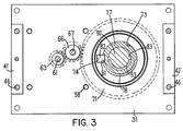
- a pinion 63 is fixedly secured to the upper end of the shaft 61, the axial length of the pinion being slightly less than the distance between the plates 31 and 43 so that the pinion 63 can rotate between the plates with no significant frictional engagement therewith.
- An idler gear 66 disposed between the plates 31 and 43 also has an axial length slightly less than the distance between the plates, the idler gear 66 being rotatably supported on a vertically extending cylindrical pin 67 having its ends disposed in blind holes in the plates 31 and 43.
- the idler gear 66 has teeth which meshingly engage teeth on the pinion 63.
- a drive gear 71 which has a substantially larger diameter than either the pinion 63 or idler 66, the drive gear 71 having an axial length which is slightly less than the distance between the plates 31 and 43 so that it can rotate therebetween with minimal friction.
- the drive gear 71 has teeth on its periphery which meshingly engage the teeth on the idler gear 66.
- the drive gear 71 also has a cylindrical central opening 73 extending vertically therethrough, the opening 73 being equal in diameter to and being coaxially aligned with the openings 33 and 52 in the guide portions 32 and 51.
- the drive gear 71 also has in one side of the central opening 73 a rectangular axial groove 74 which serves as a keyway.
- An elongate, cylindrical, tubular outer screw member 77 is made of metal and has a helical thread 78 extending along its outer surface.
- the outside diameter of the screw member 77, including the thread, is slightly less than the diameters of the openings 33 and 52 in the guide portions 32 and 51, so that the screw member 77 can move axially within the openings without significant friction and with negligible radial play.
- the outer screw member 77 extends through the openings 33 and 52, and the thread 78 thereon engages the thread of the nut 37.
- the screw member 77 has in an external surface thereof an axially-extending slot 81 ( Figure 3) of rectangular cross section.
- a rectangular metal key 82 is provided between the plates 31 and 43 in engagement with the keyway 74 in drive gear 71 and the slot 81 in outer screw member 77.
- the key 82 is held against axial movement by the plates 31 and 43, but is axially slidable within the slot 81 in the outer screw member 77.
- the key 82 is a separate structural part in the preferred embodiment, it will be recognized that it could alternatively be an integral part of the drive gear 71.
- a central opening 83 through the outer screw member 77 is cylindrical, and an annular rectangular groove 86 is provided in the surface of the opening 83 at a location spaced from the upper end of outer screw member 77 by a distance which is approximately a quarter of the axial length of the member 77.
- a sleeve-like nut 87 is disposed within the groove 86, a helical internal thread on the nut 87 projecting radially inwardly into the opening 83 from an inner surface of the nut which has a diameter equal to or slightly greater than the diameter of the opening 83.
- the outer screw member 77 also has an annular groove 88 provided in the exterior surface thereof at a location spaced a short distance above the lower end of member 77.
- An annular ring 89 is disposed in the groove 88, the outer diameter of the ring 89 preferably being slightly greater than the outer diameter of the thread 78 on member 77, so that the ring 89 rather than the thread slidably engages the inner surface of opening 33.
- the ring is made of polytetrafluoroethylene (which is commonly referred to with the trademark Teflon), but there are other materials which would also be suitable.
- An elongate, cylindrical, inner metal screw member 92 has a helical thread 93 extending along an exterior surface thereof, the outside diameter of the screw member 92, including thread 93, being slightly less than the diameter of the central opening 83 through the outer screw member 77, so that the screw member 92 can move axially within the opening 83 without significant friction and with negligible radial play.
- the inner screw member 92 extends within the central opening 83 in the outer screw member 77, the helical thread 93 engaging the thread on nut 87.
- An annular groove 96 is provided in the exterior surface of the inner screw member 92 a short distance above the lower end thereof, and an annular ring 97 is disposed within the groove 96, the ring 97 preferably being made of the same material as the ring 89.
- the outside diameter of the ring 97 preferably is slightly larger than the outside diameter of the thread 93 on the screw member 92.
- a metal fitting 102 has a cylindrical stem 103 with a diameter substantially equal to the outside diameter of the thread 93 on the inner screw member 92, and has at the upper end of the cylindrical stem 103 a radially outwardly projecting annular flange 106.
- the stem 103 extends through a circular opening 107 provided in the plate 21 of the frame 16 ( Figure 1), the diameter of the hole 107 being approximately equal to the diameter of the stem 103.
- the flange 106 is disposed against the upper surface of the plate 21, and is fixedly secured thereto by a welding bead 108.
- a screw 112 has a shank extending downwardly through a central opening in the fitting 102 and threadedly engaging a vertical threaded hole 113 provided in the upper end of the inner screw member 92.
- the screw 112 and fitting 102 rigidly secure the inner screw member 92 to the plate 21 and prevent relative rotation therebetween.
- Figure 5 An alternative embodiment of the inventive apparatus is shown in Figure 5.
- the embodiment of Figure 5 is identical to the embodiment just described, and thus only the differences are described in detail.
- Components in Figure 5 which correspond directly to components in Figures 1-4 are identified with the same reference numerals.
- the embodiment of Figure 5 lacks a nut equivalent to that shown at 37 in Figure 4, and lacks a key equivalent to that shown at 82 in Figure 4.
- the drive gear 171 in Figure 5 has therethrough a central opening 172 which is threaded and which directly cooperates with the helical thread 178 on the outer screw member 177.
- the outer screw member 177 has an annular groove provided in the exterior surface thereof a short distance below its upper end, and disposed in the annular groove 184 is an annular ring 185.
- the annular ring 185 is preferably made of the same material as the annular rings 89 and 97.
- the outer diameter of the annular ring 185 preferably is slightly greater than the outer diameter of the thread 178 on outer screw member 177.
- the motor 56 is energized in a manner effecting rotation of the shaft 61 in a forward rotational direction.
- the pinion 63 rotates with the shaft 61 and rotates the idler gear 66, which in turn rotates the drive gear 71.
- the key 82 causes the outer screw member 77 to rotate synchronously with the drive gear 71, and the rotation of the outer screw member 77 relative to nut 37 causes the outer screw member 77 to move upwardly relative to the nut 37, gear 71 and plates 31 and 43.
- the key 82 slides within the lengthwise slot 81 in the outer screw member 77.
- the motor 56 is simply energized so that the shaft 61 rotates in a reverse direction, and the illustrated structure telescopically contracts in a manner opposite but analogous to the above-described telescopic extension thereof.
- the motor 56 can be stopped at any point. If it continues to run, the plate 21 will eventually engage the upper end of the guide portion 51 as shown in Figure 2 in order to forcibly halt movement of the screw members 77 and 92.
- groove 88 and ring 89 could be omitted in the embodiment of Figures 1-4. Since the screw members 92 and 77 move synchronously, engagement of the ring 97 with the nut 87 will halt rotation of screw member 77 and thus halt axial movement of both of the screw members 92 and 77. It would also be possible to omit the ring 97 and groove 96, in which case the inner screw member 92 would stop moving upwardly when its lower end reached the top of nut 87, there being enough remaining axial overlap of the members 92 and 77 to keep the member 92 properly vertically supported by member 77. Likewise, the outer screw member 77 would stop moving upwardly when its lower end reached the top of nut 37, and then the guide portion 51 would continue to maintain the member 77 in a proper vertical orientation.
- the outer screw member 177 will move upwardly relative to the drive gear 171 without rotating.
- the annular ring 89 will engage the drive gear 171 and thereby force the outer screw member 177 to stop moving upwardly and to begin rotating with the drive gear 171.
- This rotation of the outer screw member 177 causes the nut 87 thereon to rotate around the stationary inner screw member 92, and thus the inner screw member 92 will move upwardly relative to the outer screw member 177.
- the annular ring 97 will engage the nut 87 and thus forcibly halt movement of the illustrated components.
- the motor is operated in an opposite direction and the components will return to their original positions in a manner opposite but analogous to that described above for telescopic extension thereof.
- the outer screw member 177 may initially move downwardly relative to the rotating drive gear 171 until the annular ring 185 engages the drive gear 171, after which the inner screw member 92 will move downwardly relative to the outer screw member 177 until the plate 21 engages the upper end of the outer screw member 177.
- the outer screw member 177 may initially rotate with the rotating drive gear 177 so that it does not move downwardly but instead the inner screw member 92 moves downwardly relative to the outer screw member 177 until the plate 21 engages the upper end of outer screw member 177, after which the outer screw member 177 will be held against rotation and thus will move downwardly relative to the rotating drive gear 171 until the annular ring 185 engages the drive gear 171 and halts movement of the illustrated components.
Landscapes
- Health & Medical Sciences (AREA)
- Nursing (AREA)
- Life Sciences & Earth Sciences (AREA)
- Animal Behavior & Ethology (AREA)
- General Health & Medical Sciences (AREA)
- Public Health (AREA)
- Veterinary Medicine (AREA)
- Transmission Devices (AREA)
- Invalid Beds And Related Equipment (AREA)
Claims (17)
- Krankenhausbettvorrichtung, umfassend ein erstes und ein zweites Teil (12, 16), wobei das genannte erste oder das genannte zweite Teil ein Basisabschnitt (12) und das jeweils andere ein Tragabschnitt (16) ist, der sich über dem genannten Basisabschnitt befindet und eine Person tragen kann, und selektiv betätigbare beabstandete erste und zweite Hubmechanismen (17, 18), die betriebsmäßig mit dem genannten ersten und dem zweiten Teil verbunden sind und die eine relative vertikale Bewegung zwischen dem genannten ersten und dem genannten zweiten Teil bewirken können, wobei jeder der genannten Hubmechanismen folgendes umfaßt: ein erstes Element (37, 171), das auf dem genannten zweiten Teil aufliegt, wobei das genannte erste Element eine dadurch verlaufende vertikale Öffnung mit Innengewinde aufweist, ein zweites Element (77), das eine längliche Röhre mit Außengewinde und einem Innengewindeabschnitt ist, wobei das genannte zweite Element durch die genannte Öffnung in dem genannten ersten Element (37, 171) so verläuft, daß das genannte Außengewinde an dem genannten zweiten Element (77) in das Innengewinde der genannten, durch das genannte erste Element (37, 171) verlaufenden Öffnung eingreift, ein drittes Element (92), das ein längliches Element mit Außengewinde ist, wobei das genannte dritte Element (92) einen Abschnitt aufweist, der in das genannte zweite Element (77) so verläuft, daß das Außengewinde an dem genannten dritten Element (92) in den Innengewindeabschnitt des genannten zweiten Elementes (77) eingreift, ein Mittel (101, 102, 103, 112) zum Verhindern einer Drehung der genannten dritten Elemente (92) um ihre Längsachsen relativ zueinander und relativ zu dem genannten ersten Teil (12 bzw. 16), wobei gleichzeitig ein Ende jedes genannten dritten Elementes mit dem genannten ersten Teil verbunden ist, gekennzeichnet durch ein Mittel (31, 131, 36, 43) zum Verhindern einer vertikalen Bewegung des genannten ersten Elementes in bezug auf das genannte zweite Teil; durch unabhängig steuerbare erste und zweite Umkehrantriebsmotoren (56), die jeweils eine drehbare Antriebswelle (61) aufweisen; und durch einen ersten und einen zweiten Antriebszug (63, 66, 71, 171), die jeweils auf eine Drehung der Antriebswelle (61) eines jeweiligen der genannten Motoren (56) reagieren, um eine relative Drehung zwischen einem jeweiligen der genannten zweiten Elemente (77) und wenigstens einem der genannten ersten (37, 171) und dritten (92) Elemente zu bewirken, die damit im Gewindeeingriff stehen.
- Krankenhausbettvorrichtung nach Anspruch 1, dadurch gekennzeichnet, daß jedes der genannten ersten Elemente (37) eine Mutter ist, die mit dem genannten zweiten Teil (12 oder 16) fest verbunden ist, daß jedes genannte zweite Element (77) einen längsverlaufenden Schlitz (81) in einer seiner Außenflächen aufweist, und daß jeder genannte Antriebszug ein Antriebselement (71) umfaßt, das drehbar auf dem genannten zweiten Teil aufliegt, das darauf einen Keilwellenabschnitt (82) hat, der axial verschiebbar in dem genannten Schlitz (81) in dem genannten zweiten Element angeordnet ist, und das sich in Reaktion auf eine Drehung der Antriebswelle (61) des entsprechenden Antriebsmotors (56) in jeweilige Richtungen in eine erste bzw. zweite Richtung dreht.
- Krankenhausbettvorrichtung nach Anspruch 2, dadurch gekennzeichnet, daß das genannte Mittel (31, 131, 36, 43) zum Verhindern einer vertikalen Bewegung zwei Paare von vertikal beabstandeten und horizontal verlaufenden Platten (31, 43) umfaßt, die fest darauf aufliegen, wobei jedes genannte Antriebselement (71) zwischen genannten Platten eines jeweiligen genannten Paares angeordnet ist und eine axiale Länge aufweist, die geringfügig kleiner ist als der vertikale Abstand zwischen den Platten.
- Krankenhausbettvorrichtung nach Anspruch 3, dadurch gekennzeichnet, daß jedes genannte Antriebselement (71) ein Antriebszahnrad ist, und wobei jeder genannte Antriebszug (63, 66, 71) eine Zahnradfolge umfaßt, die zwischen den genannten Platten (31, 43) eines jeweiligen genannten Paares angeordnet ist und die Antriebswelle eines jeweiligen genannten Antriebsmotors mit dem zugehörigen Antriebszahnrad antreibend verbindet.
- Krankenhausbettvorrichtung nach Anspruch 3, dadurch gekennzeichnet, daß die genannten Platten (31, 43) jedes genannten Paares durch sie verlaufende ausgerichtete vertikale Öffnungen (33, 52) aufweisen, durch die ein jeweiliges genanntes zweites Element (77) verläuft, und umfassend eine Mehrzahl röhrenförmiger Führungsabschnitte (32, 51), die jeweils auf einer jeweiligen genannten Platte koaxial zu der genannten durch sie verlaufenden Öffnung und auf einer Seite der Platte entfernt von der anderen Platte des Paares aufliegen, wobei jeder genannte röhrenförmige Führungsabschnitt (32, 51) einen Innendurchmesser hat, der geringfügig größer ist als ein Außendurchmesser des durch sie verlaufenden zweiten Elementes (77).
- Krankenhausbettvorrichtung nach Anspruch 1, dadurch gekennzeichnet, daß jedes genannte erste Element (37, 171) ein Antriebselement ist, das drehbar auf dem genannten zweiten Teil liegt, und umfassend Mittel (88, 89, 96, 97) zum Begrenzen einer Aufwärts- und Abwärtsbewegung jedes genannten zweiten Elementes (77) relativ zu dem Antriebselement (71, 171), das damit im Gewindeeingriff steht, und ein Mittel (87) zum Begrenzen einer Aufwärts- und Abwärtsbewegung jedes genannten dritten Elementes (92) relativ zum zweiten Element (77), das damit im Gewindeeingriff steht.
- Krankenhausbettvorrichtung nach Anspruch 6, dadurch gekennzeichnet, daß das genannte Mittel (31, 131, 36, 43) zum Verhindern einer vertikalen Bewegung zwei Paare von vertikal beabstandeten und horizontal verlaufenden Platten (31, 43) umfaßt, die fest auf dem genannten zweiten Teil (12 bzw. 16) aufliegen, wobei jedes genannte Antriebselement (37, 171) zwischen den Platten eines jeweiligen genannten Paares angeordnet ist und eine axiale Länge hat, die geringfügig kleiner ist als der Abstand zwischen den Platten.
- Krankenhausbettvorrichtung nach Anspruch 7, dadurch gekennzeichnet, daß jedes genannte Antriebselement (37, 171) ein Antriebszahnrad ist und daß jeder genannte Antriebszug (63, 66, 71) eine Zahnradfolge umfaßt, die zwischen den genannten Platten (31, 43) eines jeweiligen genannten Paares angeordnet ist und die Antriebswelle (61) eines jeweiligen genannten Antriebsmotors (56) mit dem zugehörigen Antriebszahnrad antreibend verbindet.
- Krankenhausbettvorrichtung nach Anspruch 7, dadurch gekennzeichnet, daß die genannten Platten (31, 43) jedes genannten Paares durch sie verlaufende, ausgerichtete vertikale Öffnungen (33, 52) aufweisen, durch die ein jeweiliges genanntes zweites Element (77) verläuft, und umfassend eine Mehrzahl röhrenförmiger Führungsabschnitte (32, 51), die jeweils auf einer jeweiligen genannten Platte koaxial zu der genannten durch sie verlaufenden Öffnung und auf einer Seite der Platte entfernt von der anderen Platte des Paares aufliegen, wobei jeder genannte röhrenförmige Führungsabschnitt (32, 51) einen Innendurchmesser hat, der geringfügig größer ist als ein Außendurchmesser des zweiten durch sie verlaufenden Elementes (77).
- Krankenhausbettvorrichtung nach Anspruch 1, gekennzeichnet durch eine Mehrzahl von Fußrollen (13), die an dem genannten Basisabschnitt (12) vorgesehen sind, um den genannten Basisabschnitt bewegbar auf der Bodenfläche zu tragen.
- Krankenhausbettvorrichtung nach Anspruch 1, dadurch gekennzeichnet, daß das genannte erste Mittel eine Mutter (37) umfaßt, die fest mit dem genannten zweiten Teil (12) verbunden ist und von dem genannten Mittel (31, 131, 36, 43) zum Verhindern einer vertikalen Bewegung in bezug auf das genannte zweite Teil gehalten wird, wobei die genannte Mutter (37) im Gewindeeingriff mit dem genannten Außengewinde am genannten zweiten Element (77) steht, wobei eine Drehung des genannten zweiten Elementes (77) relativ zu der genannten Mutter (37) eine vertikale Bewegung des genannten zweiten Elementes relativ zu dem genannten zweiten Teil (12) und eine vertikale Bewegung des genannten dritten Elementes (92) relativ zu dem genannten zweiten Element (77) bewirkt; daß das genannte zweite Element (77) einen längsverlaufenden Schlitz (81) in einer seiner Außenflächen aufweist; und daß der genannte Antriebszug (63, 66, 71, 171) auch eine relative Drehung zwischen dem zweiten Element (77) und dem zweiten Teil (12) bewirkt und ein Antriebszahnrad (71) umfaßt, das drehbar auf dem genannten zweiten Teil (12) aufliegt und darauf einen Keilwellenabschnitt (82) hat, der axial verschiebbar in dem genannten Schlitz (81) in dem genannten zweiten Element (77) angeordnet ist; ein Zwischenzahnrad (66), das drehbar auf dem genannten zweiten Teil (12) aufliegt und antreibend in das genannte Antriebszahnrad (63) eingreift, wobei der genannte Umkehrantriebsmotor (56) auf dem genannten zweiten Teil (12) aufliegt und auf seiner Antriebswelle (61) ein Ritzel (63) aufweist, das antreibend in das genannte Zwischenzahnrad eingreift.
- Krankenhausbettvorrichtung nach Anspruch 11, dadurch gekennzeichnet, daß das genannte Mittel (31, 131, 36, 43) zum Verhindern einer vertikalen Bewegung vertikal beabstandete und horizontal verlaufende erste und zweite Platten (31, 43) umfaßt, wobei das genannte Ritzel (63), das genannte Zwischenzahnrad (66) und das genannte Antriebszahnrad (71) jeweils zwischen der genannten ersten und der genannten zweiten Platte (31, 43) angeordnet sind und eine axiale Länge aufweisen, die geringfügig kleiner ist als der vertikale Abstand zwischen den genannten Platten.
- Krankenhausbettvorrichtung nach Anspruch 12, umfassend zwei röhrenförmige Führungsabschnitte (32, 51), die jeweils an einer jeweiligen der genannten Platten (31, 43) an einer ihrer Seiten gegenüber der anderen der genannten Platten fest angebracht sind, wobei die genannten Führungsabschnitte (32, 51) jeweils eine durch sie verlaufende mittlere Öffnung (33, 52) mit einem Durchmesser aufweisen, der geringfügig größer ist als ein Außendurchmesser des genannten Außengewindes am genannten zweiten Element (77), wobei die genannten mittleren Öffnungen in den genannten Führungsabschnitten koaxial zueinander und zu einer Rotationsachse des genannten Antriebszahnrades (71) ausgerichtet sind.
- Krankenhausbettvorrichtung nach einem der Ansprüche 11 bis 13, gekennzeichnet durch ein Mittel (88, 89, 96, 97) zum Begrenzen einer Aufwärts- und Abwärtsbewegung des genannten zweiten Elementes (77) relativ zu dem genannten Antriebszahnrad (71) und ein Mittel (87) zum Begrenzen einer Aufwärts- und Abwärtsbewegung des genannten dritten Elementes (92) relativ zu dem genannten zweiten Element.
- Krankenhausbettvorrichtung nach Anspruch 1, gekennzeichnet durch ein Mittel (88, 89, 96, 97) zum Begrenzen einer Aufwärts- und Abwärtsbewegung des genannten zweiten Elementes (77) relativ zu dem genannten Antriebselement (71), umfassend axial beabstandete Umfangsrillen (88, 96) in dem zweiten Element (77) und in jeder der genannten Umfangsrillen einen Anschlagring (89, 97) mit einem Außendurchmesser, der im wesentlichen einem Außendurchmesser des genannten Außengewindes an dem genannten zweiten Element (77) entspricht; und ein Mittel (87) zum Begrenzen einer Aufwärts- und Abwärtsbewegung des genannten dritten Elementes (92) relativ zu dem genannten zweiten Element, umfassend eine Umfangsrille (96) in dem genannten dritten Element und in der genannten Umfangsrille einen Anschlagring (97) mit einem Außendurchmesser, der im wesentlichen dem Außendurchmesser des Gewindes an dem genannten Gewindeelement entspricht.
- Krankenhausbettvorrichtung nach Anspruch 15, dadurch gekennzeichnet, daß das genannte zweite Teil (12) einen ersten und einen zweiten röhrenförmigen Führungsabschnitt (32, 151) umfaßt, die fest auf dem genannten zweiten Teil (12) auf gegenüberliegenden Seiten des genannten Antriebselementes (71) aufliegen, wobei die genannten Führungsabschnitte (32, 151) jeweils eine durch sie verlaufende Öffnung (33, 52) mit einem Durchmesser aufweisen, der geringfügig größer ist als ein Außendurchmesser des genannten Außengewindes am genannten zweiten Element (77), wobei die genannten Öffnungen in den genannten Führungsabschnitten koaxial verlaufen und das genannte zweite Element darin koaxial dazu verläuft.
- Krankenhausbettvorrichtung nach Anspruch 16, dadurch gekennzeichnet, daß das genannte Antriebselement (71) ein Zahnrad ist, wobei die genannte Zahnradfolge ein Zwischenzahnrad (66) umfaßt, das drehbar auf dem genannten zweiten Teil (12) aufliegt und antreibend in das genannte Antriebselement (71) eingreift, wobei der genannte Umkehrantriebsmotor (56) fest auf dem genannten zweiten Teil (12) aufliegt und auf seiner Antriebswelle (61) ein Ritzel (63) aufweist, das antreibend in das genannte Zwischenzahnrad (66) eingreift, und daß das genannte Mittel (31, 43) zum Verhindern einer vertikalen Bewegung erste und zweite vertikal beabstandete und horizontal verlaufende Platten (31, 43) umfaßt, die fest auf dem genannten zweiten Teil aufliegen, wobei das genannte Antriebselement (71), das Zwischenzahnrad (66) und das Ritzel (63) zwischen den genannten Platten angeordnet sind und eine axiale Länge aufweisen, die geringfügig kleiner ist als der Abstand zwischen den genannten Platten, wobei jede der genannten Platten einen fest darauf angebrachten jeweiligen der genannten Führungsabschnitte (32, 51) hat und eine durch sie verlaufende Öffnung (33, 52) aufweist, die auf die durch die genannten Führungsabschnitte verlaufenden Öffnungen (33, 52) ausgerichtet ist.
Applications Claiming Priority (3)
| Application Number | Priority Date | Filing Date | Title |
|---|---|---|---|
| US07/816,826 US5172442A (en) | 1992-01-03 | 1992-01-03 | Litter support having telescoping threaded rod arrangement |
| US816826 | 1992-01-03 | ||
| PCT/US1993/000068 WO1993012750A1 (en) | 1992-01-03 | 1993-01-04 | Litter support having telescoping threaded rod arrangement |
Publications (3)
| Publication Number | Publication Date |
|---|---|
| EP0573647A1 EP0573647A1 (de) | 1993-12-15 |
| EP0573647A4 EP0573647A4 (de) | 1995-05-24 |
| EP0573647B1 true EP0573647B1 (de) | 1999-04-14 |
Family
ID=25221714
Family Applications (1)
| Application Number | Title | Priority Date | Filing Date |
|---|---|---|---|
| EP93903397A Expired - Lifetime EP0573647B1 (de) | 1992-01-03 | 1993-01-04 | Krankenhausbett |
Country Status (6)
| Country | Link |
|---|---|
| US (1) | US5172442A (de) |
| EP (1) | EP0573647B1 (de) |
| CA (1) | CA2103900A1 (de) |
| DE (1) | DE69324405T2 (de) |
| GR (1) | GR3030244T3 (de) |
| WO (1) | WO1993012750A1 (de) |
Families Citing this family (48)
| Publication number | Priority date | Publication date | Assignee | Title |
|---|---|---|---|---|
| US5343581A (en) * | 1992-10-21 | 1994-09-06 | Stryker Corporation | Housing and drive mechanism for screw lift of hospital bed |
| US5398356A (en) * | 1993-06-28 | 1995-03-21 | Pfleger; Frederick W. | X-ray table |
| DE4322227C1 (de) * | 1993-07-03 | 1994-08-25 | Vauth Sagel Gmbh & Co | Kranken- oder Pflegebett |
| US5636394A (en) * | 1995-04-28 | 1997-06-10 | Stryker Corporation | Hospital bed with rack and pinion stabilizer |
| US6772456B2 (en) | 1995-09-13 | 2004-08-10 | Hill-Rom Services, Inc. | Portable device for patient pullup, rollover, and transfer and methods thereof |
| US5967728A (en) * | 1997-11-26 | 1999-10-19 | Emtrol, Inc. | Precision placement storage and retrieval system |
| US6202275B1 (en) | 1997-12-12 | 2001-03-20 | Maglev, Inc. | Precision assembly table and method |
| US6058532A (en) * | 1998-03-30 | 2000-05-09 | Allen; Newton P. | Apparatus for elevating one end portion of a bed frame |
| BR9916131A (pt) * | 1998-12-11 | 2001-11-06 | Hill Rom Co Inc | Montagens de cama, de apoio de paciente para uma cama articulada e de manìpulo de empurrar articulado para camas de hospital, e, cama de hospital |
| WO2000056259A1 (de) * | 1999-03-22 | 2000-09-28 | Völker Möbelproduktionsgesellschaft mbH | Bett, insbesondere kranken- und/oder pflegebett und längenveränderbares stützelement für ein derartiges bett |
| US6253878B1 (en) * | 1999-08-17 | 2001-07-03 | Dale Wells | Ergonomically adjustable machine operator platform |
| DE19955455B4 (de) * | 1999-11-17 | 2005-07-14 | Koch, Michael, Dipl.-Ing. (FH) | Höhenverstellbares Pflegebett |
| DE10151754B4 (de) * | 2001-10-19 | 2005-01-20 | Klaus Priv.-Doz. Dr. med. Seide | Längeneinstellelement |
| US7111338B2 (en) | 2002-06-17 | 2006-09-26 | Hill-Rom Services, Inc. | Apparatus for pulling patient up in bed |
| US7065811B2 (en) | 2003-03-18 | 2006-06-27 | Hill-Rom Services, Inc. | Radial arm system for patient care equipment |
| CA2534654C (en) | 2003-07-31 | 2013-01-08 | C. Rasmussen Martin | System and method for moving objects |
| US7290299B2 (en) | 2004-01-09 | 2007-11-06 | Votel Thomas W | Device and method for positioning patients |
| US7182316B2 (en) * | 2004-02-05 | 2007-02-27 | Sykes Richard D | Adjustable support bracket |
| US7003829B2 (en) * | 2004-07-26 | 2006-02-28 | Byung Ki Choi | Stretcher with gear mechanism for adjustable height |
| US7725964B2 (en) | 2004-08-27 | 2010-06-01 | Hill-Rom Services, Inc. | Apparatus with patient adjustment device coupled to architectural system |
| US7398571B2 (en) | 2004-09-24 | 2008-07-15 | Stryker Corporation | Ambulance cot and hydraulic elevating mechanism therefor |
| JP5055523B2 (ja) | 2004-09-24 | 2012-10-24 | ストライカー コーポレイション | 救急車用簡易ベッド及びそのための油圧式昇降機構 |
| US7503084B1 (en) * | 2005-02-25 | 2009-03-17 | Michael Norman Terry | Integrated mattress leveling system |
| US7712389B2 (en) * | 2006-05-16 | 2010-05-11 | T-Motion Technology Co., Ltd. | Lifting device having parallel double screw rods |
| US8291532B2 (en) * | 2006-06-21 | 2012-10-23 | Hill-Rom Services, Inc. | Canister lift for a patient support apparatus |
| US8864205B2 (en) | 2006-06-28 | 2014-10-21 | Stryker Corporation | Patient support with wireless data and/or energy transfer |
| WO2008003027A2 (en) * | 2006-06-28 | 2008-01-03 | Stryker Corporation | Patient support |
| JP2012514703A (ja) | 2008-12-31 | 2012-06-28 | エフ. ヒメネス、オマール | フレキシャ部材を組み入れた可撓性ジョイント構成 |
| US8628577B1 (en) | 2009-03-19 | 2014-01-14 | Ex Technology, Llc | Stable device for intervertebral distraction and fusion |
| IN2012DN00952A (de) | 2009-07-22 | 2015-04-10 | Spinex Tec Llc | |
| CN201469273U (zh) * | 2009-08-18 | 2010-05-19 | 上海西门子医疗器械有限公司 | 一种检查床的垂直运动装置 |
| US8636746B2 (en) | 2009-12-31 | 2014-01-28 | Spinex Tec, Llc | Methods and apparatus for insertion of vertebral body distraction and fusion devices |
| FI20100042L (fi) * | 2010-02-05 | 2011-08-18 | Veli-Matti Ilari Jussila | Nostolavarakenne |
| US8636157B2 (en) * | 2010-12-20 | 2014-01-28 | Mi-Jack Products, Inc. | Screw-driven vertically-elevating cab |
| DE102012211712A1 (de) * | 2012-07-05 | 2014-01-09 | Aktiebolaget Skf | Tisch mit zumindest einer Führungseinheit |
| WO2014105046A1 (en) * | 2012-12-28 | 2014-07-03 | Tempur-Pedic Management, Llc | Bed with mattress assembly having one or more internal plates |
| US9486328B2 (en) | 2014-04-01 | 2016-11-08 | Ex Technology, Llc | Expandable intervertebral cage |
| US9656590B2 (en) | 2014-05-15 | 2017-05-23 | Lippert Components, Inc. | Bed lift mounting member |
| CN104257465B (zh) * | 2014-08-11 | 2016-06-01 | 孙艳艳 | 手术移送床 |
| CN104257464B (zh) * | 2014-08-11 | 2016-06-08 | 孙艳艳 | 具有升降头枕的手术移送床 |
| CN104249982B (zh) * | 2014-09-15 | 2016-11-23 | 太仓市金达机械厂 | 一种横梁水平调节装置 |
| CN108294876B (zh) * | 2018-01-08 | 2020-09-01 | 鹤壁市人民医院 | 一种用于妇产科的易于调整型病床 |
| US11497622B2 (en) | 2019-03-05 | 2022-11-15 | Ex Technology, Llc | Transversely expandable minimally invasive intervertebral cage and insertion and extraction device |
| US11234835B2 (en) | 2019-03-05 | 2022-02-01 | Octagon Spine Llc | Transversely expandable minimally invasive intervertebral cage |
| CN113712755A (zh) * | 2021-09-07 | 2021-11-30 | 杨秋凤 | 一种具有杀菌功能的icu智能护理病床 |
| US12097126B2 (en) | 2021-09-29 | 2024-09-24 | Ex Technology, Llc | Expandable intervertebral cage |
| US12011365B2 (en) | 2022-07-18 | 2024-06-18 | Octagon Spine Llc | Transversely expandable minimally invasive inter vertebral cage |
| US20240138588A1 (en) * | 2022-11-02 | 2024-05-02 | Jorge Rafael Da Silva Neto | Adjustable universal crib mattress device |
Family Cites Families (9)
| Publication number | Priority date | Publication date | Assignee | Title |
|---|---|---|---|---|
| DE352059C (de) * | 1922-04-20 | Siemens & Halske Akt Ges | Heb- und senkbarer Tisch fuer Roentgenbestrahlungen | |
| US1565878A (en) * | 1924-06-13 | 1925-12-15 | William E Pratt | Lifting jack |
| US1906365A (en) * | 1928-05-18 | 1933-05-02 | Elite Mfg Company | Vehicle jack |
| US1874357A (en) * | 1929-01-14 | 1932-08-30 | Dayton Malleable Iron Co | Jack |
| US1874772A (en) * | 1929-07-29 | 1932-08-30 | Dayton Malleable Iron Co | Lifting jack |
| US2127309A (en) * | 1937-04-03 | 1938-08-16 | Guy O Squire | Hospital stretcher |
| US2522759A (en) * | 1947-10-23 | 1950-09-19 | Lindquist Marie | Adjustable bed |
| US3253284A (en) * | 1965-02-08 | 1966-05-31 | Gendron Wheel Company | Adjustable stretcher |
| GB2175274A (en) * | 1985-04-19 | 1986-11-26 | Shinn I Chern | Improved screw jack |
-
1992
- 1992-01-03 US US07/816,826 patent/US5172442A/en not_active Expired - Lifetime
-
1993
- 1993-01-04 EP EP93903397A patent/EP0573647B1/de not_active Expired - Lifetime
- 1993-01-04 DE DE69324405T patent/DE69324405T2/de not_active Expired - Fee Related
- 1993-01-04 CA CA002103900A patent/CA2103900A1/en not_active Abandoned
- 1993-01-04 WO PCT/US1993/000068 patent/WO1993012750A1/en not_active Ceased
-
1999
- 1999-05-19 GR GR990401336T patent/GR3030244T3/el unknown
Also Published As
| Publication number | Publication date |
|---|---|
| CA2103900A1 (en) | 1993-07-04 |
| EP0573647A4 (de) | 1995-05-24 |
| WO1993012750A1 (en) | 1993-07-08 |
| GR3030244T3 (en) | 1999-08-31 |
| US5172442A (en) | 1992-12-22 |
| EP0573647A1 (de) | 1993-12-15 |
| DE69324405D1 (de) | 1999-05-20 |
| DE69324405T2 (de) | 1999-08-05 |
Similar Documents
| Publication | Publication Date | Title |
|---|---|---|
| EP0573647B1 (de) | Krankenhausbett | |
| US5282593A (en) | Adjustable leg | |
| US5018225A (en) | Appparatus for preventing and healing bedsores in long-term inpatients | |
| US5802639A (en) | Variable force clutch for linear actuator | |
| AU2001260086B2 (en) | Telescopically moving structure | |
| US4552403A (en) | Power-operated medical examination table | |
| US5146638A (en) | Bath | |
| US6435048B1 (en) | Multi-leg telescopic linear actuator | |
| US5343581A (en) | Housing and drive mechanism for screw lift of hospital bed | |
| US4435861A (en) | Ledge bed | |
| US3698673A (en) | Base for adjustable chairs | |
| WO2000056259A1 (de) | Bett, insbesondere kranken- und/oder pflegebett und längenveränderbares stützelement für ein derartiges bett | |
| US10028874B2 (en) | Operating table base for an operating table | |
| EP0685216B1 (de) | Bett, insbesondere Krankenbett | |
| US5201084A (en) | Screw driven lift mechanism for a hospital patient chair transfer system | |
| EP4057974B1 (de) | Hebesäule | |
| DE2844436A1 (de) | Hebebock | |
| JP3152635U (ja) | 昇降テーブル | |
| US4778137A (en) | Lift base | |
| DE4122116A1 (de) | Krankenhebevorrichtung | |
| US3149822A (en) | Permanent auto-jack | |
| JPH059876Y2 (de) | ||
| CN215014446U (zh) | 一种自动升降桌 | |
| JPH053640Y2 (de) | ||
| JPH04371497A (ja) | 多段式昇降装置 |
Legal Events
| Date | Code | Title | Description |
|---|---|---|---|
| PUAI | Public reference made under article 153(3) epc to a published international application that has entered the european phase |
Free format text: ORIGINAL CODE: 0009012 |
|
| AK | Designated contracting states |
Kind code of ref document: A1 Designated state(s): DE FR GB GR NL |
|
| 17P | Request for examination filed |
Effective date: 19931216 |
|
| A4 | Supplementary search report drawn up and despatched | ||
| AK | Designated contracting states |
Kind code of ref document: A4 Designated state(s): DE FR GB GR NL |
|
| 17Q | First examination report despatched |
Effective date: 19961106 |
|
| GRAG | Despatch of communication of intention to grant |
Free format text: ORIGINAL CODE: EPIDOS AGRA |
|
| GRAG | Despatch of communication of intention to grant |
Free format text: ORIGINAL CODE: EPIDOS AGRA |
|
| GRAH | Despatch of communication of intention to grant a patent |
Free format text: ORIGINAL CODE: EPIDOS IGRA |
|
| GRAH | Despatch of communication of intention to grant a patent |
Free format text: ORIGINAL CODE: EPIDOS IGRA |
|
| GRAA | (expected) grant |
Free format text: ORIGINAL CODE: 0009210 |
|
| AK | Designated contracting states |
Kind code of ref document: B1 Designated state(s): DE FR GB GR NL |
|
| PG25 | Lapsed in a contracting state [announced via postgrant information from national office to epo] |
Ref country code: NL Free format text: LAPSE BECAUSE OF FAILURE TO SUBMIT A TRANSLATION OF THE DESCRIPTION OR TO PAY THE FEE WITHIN THE PRESCRIBED TIME-LIMIT Effective date: 19990414 |
|
| REF | Corresponds to: |
Ref document number: 69324405 Country of ref document: DE Date of ref document: 19990520 |
|
| ET | Fr: translation filed | ||
| NLV1 | Nl: lapsed or annulled due to failure to fulfill the requirements of art. 29p and 29m of the patents act | ||
| PG25 | Lapsed in a contracting state [announced via postgrant information from national office to epo] |
Ref country code: GB Free format text: LAPSE BECAUSE OF NON-PAYMENT OF DUE FEES Effective date: 20000104 |
|
| PG25 | Lapsed in a contracting state [announced via postgrant information from national office to epo] |
Ref country code: GR Free format text: LAPSE BECAUSE OF NON-PAYMENT OF DUE FEES Effective date: 20000131 |
|
| PLBE | No opposition filed within time limit |
Free format text: ORIGINAL CODE: 0009261 |
|
| STAA | Information on the status of an ep patent application or granted ep patent |
Free format text: STATUS: NO OPPOSITION FILED WITHIN TIME LIMIT |
|
| 26N | No opposition filed | ||
| GBPC | Gb: european patent ceased through non-payment of renewal fee |
Effective date: 20000104 |
|
| PG25 | Lapsed in a contracting state [announced via postgrant information from national office to epo] |
Ref country code: DE Free format text: LAPSE BECAUSE OF NON-PAYMENT OF DUE FEES Effective date: 20001101 |
|
| PG25 | Lapsed in a contracting state [announced via postgrant information from national office to epo] |
Ref country code: FR Free format text: LAPSE BECAUSE OF NON-PAYMENT OF DUE FEES Effective date: 20010928 |
|
| REG | Reference to a national code |
Ref country code: FR Ref legal event code: ST |
|
| PG25 | Lapsed in a contracting state [announced via postgrant information from national office to epo] |
Ref country code: FR Free format text: LAPSE BECAUSE OF NON-PAYMENT OF DUE FEES Effective date: 20000131 |