EP0573717A1 - Lauffleck für Absätze - Google Patents
Lauffleck für Absätze Download PDFInfo
- Publication number
- EP0573717A1 EP0573717A1 EP92311666A EP92311666A EP0573717A1 EP 0573717 A1 EP0573717 A1 EP 0573717A1 EP 92311666 A EP92311666 A EP 92311666A EP 92311666 A EP92311666 A EP 92311666A EP 0573717 A1 EP0573717 A1 EP 0573717A1
- Authority
- EP
- European Patent Office
- Prior art keywords
- resin
- layer
- lift
- layers
- molded
- Prior art date
- Legal status (The legal status is an assumption and is not a legal conclusion. Google has not performed a legal analysis and makes no representation as to the accuracy of the status listed.)
- Withdrawn
Links
- 238000010276 construction Methods 0.000 title description 12
- 229920005989 resin Polymers 0.000 claims abstract description 63
- 239000011347 resin Substances 0.000 claims abstract description 63
- 229920002803 thermoplastic polyurethane Polymers 0.000 claims abstract description 13
- 239000004677 Nylon Substances 0.000 claims abstract description 7
- 229920001778 nylon Polymers 0.000 claims abstract description 7
- 239000010410 layer Substances 0.000 description 88
- 238000000465 moulding Methods 0.000 description 8
- 230000036541 health Effects 0.000 description 7
- 239000000463 material Substances 0.000 description 5
- 239000007787 solid Substances 0.000 description 5
- 238000003780 insertion Methods 0.000 description 4
- 230000037431 insertion Effects 0.000 description 4
- 239000000853 adhesive Substances 0.000 description 3
- 230000001070 adhesive effect Effects 0.000 description 3
- 210000003423 ankle Anatomy 0.000 description 3
- 238000004040 coloring Methods 0.000 description 3
- 230000035939 shock Effects 0.000 description 3
- 239000006229 carbon black Substances 0.000 description 2
- 238000010586 diagram Methods 0.000 description 2
- 238000002347 injection Methods 0.000 description 2
- 239000007924 injection Substances 0.000 description 2
- 238000000034 method Methods 0.000 description 2
- 239000000203 mixture Substances 0.000 description 2
- 229920001875 Ebonite Polymers 0.000 description 1
- JOYRKODLDBILNP-UHFFFAOYSA-N Ethyl urethane Chemical compound CCOC(N)=O JOYRKODLDBILNP-UHFFFAOYSA-N 0.000 description 1
- XEEYBQQBJWHFJM-UHFFFAOYSA-N Iron Chemical group [Fe] XEEYBQQBJWHFJM-UHFFFAOYSA-N 0.000 description 1
- 230000009471 action Effects 0.000 description 1
- 230000008859 change Effects 0.000 description 1
- 239000002131 composite material Substances 0.000 description 1
- 230000006735 deficit Effects 0.000 description 1
- 235000019589 hardness Nutrition 0.000 description 1
- 238000001746 injection moulding Methods 0.000 description 1
- 238000004519 manufacturing process Methods 0.000 description 1
- 230000013011 mating Effects 0.000 description 1
- 239000002184 metal Substances 0.000 description 1
- 229910052751 metal Inorganic materials 0.000 description 1
- 229920003023 plastic Polymers 0.000 description 1
- 239000004033 plastic Substances 0.000 description 1
- 230000008439 repair process Effects 0.000 description 1
- 238000004904 shortening Methods 0.000 description 1
- 239000002356 single layer Substances 0.000 description 1
- 239000000126 substance Substances 0.000 description 1
Images


Classifications
-
- A—HUMAN NECESSITIES
- A43—FOOTWEAR
- A43B—CHARACTERISTIC FEATURES OF FOOTWEAR; PARTS OF FOOTWEAR
- A43B21/00—Heels; Top-pieces or top-lifts
-
- A—HUMAN NECESSITIES
- A43—FOOTWEAR
- A43B—CHARACTERISTIC FEATURES OF FOOTWEAR; PARTS OF FOOTWEAR
- A43B21/00—Heels; Top-pieces or top-lifts
- A43B21/02—Heels; Top-pieces or top-lifts characterised by the material
- A43B21/06—Heels; Top-pieces or top-lifts characterised by the material rubber
- A43B21/08—Heels; Top-pieces or top-lifts characterised by the material rubber combined hard and soft rubber
-
- A—HUMAN NECESSITIES
- A43—FOOTWEAR
- A43B—CHARACTERISTIC FEATURES OF FOOTWEAR; PARTS OF FOOTWEAR
- A43B21/00—Heels; Top-pieces or top-lifts
- A43B21/36—Heels; Top-pieces or top-lifts characterised by their attachment; Securing devices for the attaching means
- A43B21/42—Heels with replaceable or adjustable parts, e.g. top lift
Definitions
- This invention relates to a lift or sole construction for a shoe, in which the lift attached to the bottom of the heel of either a man's shoe or woman's shoe is molded into a single piece from two resin layers and which displays excellent advantages with regard to both health and wearing comfort.
- it is a general object of this invention is to provide a lift construction which increases the product value of the shoe, by molding a replaceable lift into a single piece from two resin layers, upper and lower, and, moreover, by selecting resins having properties which are suitably matched to the various needs.
- a shoe lift constructed in accordance with this invention comprises a replaceable lift attached to the bottom of the heel of the shoe.
- the lift is molded from two resin layers, upper and lower, and, in addition to one of these two resin layers being molded from a hard resin and the other being molded from a relatively soft resin, in order to mold the upper and lower resin layers into a single piece, connecting holes are formed in one of the layers and connecting projections are formed in the other layer.
- the upper layer is a nylon resin layer and the lower layer is a urethane resin layer.
- the composition described above by molding the lift into two layers, upper and lower, it is possible to mold the upper and lower layers from resin layers having properties which are suitably matched to the various needs.
- the shock-absorbing action of the soft resin layer prevents the impact force from the floor from reverberating to the head of the wearer, thus both improving the health aspect and also providing good wearing comfort.
- the hard resin layer makes it possible to ensure sufficient rigidity for the entire lift, thus eliminating the danger of the wearer twisting an ankle as a result of the manner in which the weight of the wearer is applied while walking which might cause the lift to tilt sideways.
- the shoe in the embodiment shown in Figs. 1 and 2 is a type of a woman's shoe, the invention is also equally applicable to a man's shoe.
- the shoe comprises a shoe body 1, a heel body 2 made of, in this specific example, rigid plastic which projects from the bottom rear of the shoe body 1, and a two-layer molded lift 3 which is attached to the bottom of this heel body 2 and which will be described later.
- the heel body 2 may also be molded into two separate layers, upper and lower.
- the heel body 2 described above is attached as a continuous single piece to the bottom of the shoe body 1, and a wedge-shaped notch 4 (see Fig. 2) which tapers in the inward and downward direction is formed at the bottom of the heel body 2.
- a insertion hole 5 is formed in the center part of the bottom of the heel body 2.
- the hole 5 is substantially perpendicular to the bottom surface 2a of the body 2.
- a metal mounting fixture 6 which projects upwardly from the top of the horseshoe-shaped lift 3 extends into this insertion hole 5, so that, as shown in Fig. 2, the heel body 2 and the lift 3 are connected together as a single piece.
- the mounting fixture 6 has a head or flange 6a at its bottom, and this flange 6a is embedded into the lift 3 so that the mounting fixture is secured to the lift 3 as a single piece.
- multiple vertical grooves are formed into the circumference of a shank or insertion part 6b of the mounting fixture 6 for the purpose of increasing the adhesion and also preventing the lift 3 from turning.
- the hole 5 and the insertion part 6b have mating cross-sectional shapes and the part 6b is sized to fit tightly in the hole 5.
- the notch 4 is used when removing a worn lift 3 from the heel body 2 in order to replace it. In other words, by inserting the tip of a screwdriver or similar tool D into the notch 4 as indicated by the imaginary lines in Fig.
- the lift 3 can be pried loose and removed from the heel body 2 by the principle of leverage. It should be noted that, because the notch 4 is provided on the inward-facing side of the bottom of the heel body 2, even if, for example, there is no outer covering (wrapping) around the heel, it is not especially visible from the outside, and thus there is no impairment to the appearance of the shoe.
- the lift 3 is molded from two resin layers, an upper layer 3A and a lower layer 3B.
- the lift 3 is not a solid piece made entirely of a single resin, as in the prior art, but is comprised of two resin layers, the upper layer 3A and the lower layer 3B, which divide it vertically into two approximately equal halves.
- the upper and lower layers one layer is molded from hard nylon resin, and the other layer is molded from relatively softer urethane resin. Rather than using two different resins for the upper and lower layers, it is also possible to mold both the upper and the lower layers from the same resin, for example, urethane.
- the reason for specifically using a urethane resin layer for the lower layer 3B is that, because the black coloring (colored with carbon black) used in order to present a slim appearance could result in marks being made on the floor surface while walking, this is prevented by allotting urethane resin for the lower layer and utilizing its bright, natural color.
- the reason for composing either the upper layer or the lower layer from a hard resin is that, if the upper layer 3A and the lower layer 3B were both molded into a single piece from the same soft resin, the entire lift 3 would lack rigidity, and the manner in which the weight of the wearer is applied while walking could cause the lift to tilt sideways, thus presenting the danger that the wearer may twist an ankle; however, by composing a layer which comprises one-half of the lift from a hard resin layer, it is possible to provide the rigidity required for the entire lift, thus eliminating such danger.
- the upper and lower resin layers which comprise the lift construction of this invention are not connected together into one piece by adhesive, but are composed so as to form a single piece by a male-female dovetail type of connection in the molding stage, as will be described later.
- multiple connecting projections 3b are formed so that they project from the top of the resin layer of the lower layer 3B and fit into connecting holes 3a formed in the resin layer of the upper layer 3A in order to connect the two layers together into one piece.
- connection by adhesive might be considered in order to utilize the good adhesion of the two layers if urethane resin layers are used for both the upper and lower layers, if this method were used, adhesive material could protrude from the adhesion surfaces, thus impairing the external appearance.
- another reason is to make it possible to also use nylon resins or the like having poor adhesion properties as one of the resins which compose the material of the lift.
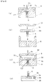
- step (a) of Fig. 3 the mounting fixture 6 described earlier is first placed and secured in the prescribed location in a die (female die) 7 having projections 7a of trapezoidal cross-sections inside it.
- a male die or cover 8 is set in place on the die 7, forming a cavity 3A' which forms the upper layer of the lift inside the dies.
- the prescribed molten resin for example, urethane resin
- the molten resin is injected in through an injection port 8a.
- the flange 6a is exposed on its top and bottom sides.
- the dies are opened and a molded piece which corresponds to the upper layer of the lift plus the fixture 6 is released from the dies.
- step (b) the molded piece which corresponds to the upper layer 3A of the lift is then placed inside a different female die 9 and a cover die 8 is placed in position in the same way as just described, as shown in step (c).
- step (c) the inside of this die is formed with a cavity 3B' for the purpose of molding the lower layer 3B of the lift.
- the layer 3A is placed on a flat bottom surface 9a of the cavity 3B', and the shank of the mounting fixture 6 extends downwardly into a hole 9b in the die 9 at the bottom of the cavity 3B'.
- the side walls 9C of the cavity 3B' fit snugly against the outer sides of the layer 3A.
- molten resin for example, nylon resin
- This nylon resin also fills the connecting holes 3a having a trapezoidal cross-section with a reverse taper which were formed in the resin of the upper layer 3A.
- the dies are opened, the molded piece is released and removed from the dies, and thus the molded lift of this invention shown in step (d) is obtained.
- connecting holes 3a mentioned above are formed with a reverse-taper trapezoidal cross-section, when they become filled by the lower layer resin, reverse-taper connecting projections 3b are formed.
- a dovetail type of connection between the layers is formed, thereby forming or connecting the resin layer of the lower layer 3B into essentially one piece with the resin layer of the upper layer 3A in such a manner that it is almost impossible for them to become separated.
- the connecting holes 3a are formed as through holes in order to make it possible to open the dies.
- the connecting projections 3b which fit into the connecting holes 3a for example, as shown in Fig.
- conically shaped or mushroom-shaped connecting projections 3b are formed on the surface of the horseshoe-shaped lower layer 3B in approximately three or four locations according to the amount of surface area.
- conically shaped or mushroom-shaped connecting projections 3b are formed on the surface of the horseshoe-shaped lower layer 3B in approximately three or four locations according to the amount of surface area.
- Fig. 6 if insert dies are used in order to make it possible to open the dies, it then becomes possible to connect the lift into one piece without using through-holes for the connecting holes as is the case in the embodiment explained above.
- Fig. 6(a) shows an example of screwhead-shaped connecting projections 3b
- Fig. 6(b) shows an example of knob-shaped connecting projections 3b.
- the upper and lower layers are composed in such a manner that it is impossible for them to become separated.
Landscapes
- Footwear And Its Accessory, Manufacturing Method And Apparatuses (AREA)
- Injection Moulding Of Plastics Or The Like (AREA)
Applications Claiming Priority (2)
| Application Number | Priority Date | Filing Date | Title |
|---|---|---|---|
| JP039999U JPH06108U (ja) | 1992-06-11 | 1992-06-11 | 靴のリフト構造 |
| JP39999/92U | 1992-06-11 |
Publications (1)
| Publication Number | Publication Date |
|---|---|
| EP0573717A1 true EP0573717A1 (de) | 1993-12-15 |
Family
ID=12568629
Family Applications (1)
| Application Number | Title | Priority Date | Filing Date |
|---|---|---|---|
| EP92311666A Withdrawn EP0573717A1 (de) | 1992-06-11 | 1992-12-21 | Lauffleck für Absätze |
Country Status (5)
| Country | Link |
|---|---|
| EP (1) | EP0573717A1 (de) |
| JP (1) | JPH06108U (de) |
| KR (1) | KR940000061A (de) |
| CN (1) | CN1079884A (de) |
| CA (1) | CA2078755A1 (de) |
Cited By (3)
| Publication number | Priority date | Publication date | Assignee | Title |
|---|---|---|---|---|
| GB2338397A (en) * | 1998-06-19 | 1999-12-22 | Supadance International Limite | Stiletto heel top piece |
| ES2157756A1 (es) * | 1999-02-05 | 2001-08-16 | Hipolito Garcia S A | Procedimiento de fabricacion de tacones para calzado. |
| WO2010129914A1 (en) * | 2009-05-07 | 2010-11-11 | Brown Shoe Company, Inc. | Top lift assembly for a shoe heel |
Families Citing this family (4)
| Publication number | Priority date | Publication date | Assignee | Title |
|---|---|---|---|---|
| JP2008264143A (ja) * | 2007-04-19 | 2008-11-06 | Tetsushi Nakamura | トップリフト、靴ヒールおよび靴 |
| JP5889314B2 (ja) * | 2010-10-11 | 2016-03-22 | ティービーエル・ライセンシング・リミテッド・ライアビリティ・カンパニー | サスペンションヒール |
| JP5696436B2 (ja) * | 2010-11-04 | 2015-04-08 | アイシン精機株式会社 | フレームモール |
| JP5986517B2 (ja) * | 2013-02-19 | 2016-09-06 | 株式会社アシックス | トップリフト |
Citations (6)
| Publication number | Priority date | Publication date | Assignee | Title |
|---|---|---|---|---|
| US2990627A (en) * | 1958-11-12 | 1961-07-04 | Stubbe Friedrich | Heel lift |
| FR2398471A1 (fr) * | 1977-07-27 | 1979-02-23 | Moeller Kg Gustav Moelde | Crampons a vis perfectionnes |
| GB2098457A (en) * | 1981-05-15 | 1982-11-24 | Dowty Seals Ltd | Studs for footwear |
| EP0388366A2 (de) * | 1989-02-10 | 1990-09-19 | BRAMUCCI, Mauro | Lauffleck für spitze Absätze mit einem doppelt mit thermoplastischem Harz beschichteten Metallkern und Herstellung des Flecks |
| EP0419317A1 (de) * | 1989-09-15 | 1991-03-27 | S.A. M3B | Schutzelement für Nadelabsätze von Schuhen |
| WO1991012741A1 (en) * | 1990-02-20 | 1991-09-05 | Fisher Camuto Corporation | Shoe with improved dual hardness heel-lift |
-
1992
- 1992-06-11 JP JP039999U patent/JPH06108U/ja active Pending
- 1992-09-21 CA CA002078755A patent/CA2078755A1/en not_active Abandoned
- 1992-11-02 CN CN92112784A patent/CN1079884A/zh active Pending
- 1992-11-06 KR KR1019920020891A patent/KR940000061A/ko not_active Withdrawn
- 1992-12-21 EP EP92311666A patent/EP0573717A1/de not_active Withdrawn
Patent Citations (6)
| Publication number | Priority date | Publication date | Assignee | Title |
|---|---|---|---|---|
| US2990627A (en) * | 1958-11-12 | 1961-07-04 | Stubbe Friedrich | Heel lift |
| FR2398471A1 (fr) * | 1977-07-27 | 1979-02-23 | Moeller Kg Gustav Moelde | Crampons a vis perfectionnes |
| GB2098457A (en) * | 1981-05-15 | 1982-11-24 | Dowty Seals Ltd | Studs for footwear |
| EP0388366A2 (de) * | 1989-02-10 | 1990-09-19 | BRAMUCCI, Mauro | Lauffleck für spitze Absätze mit einem doppelt mit thermoplastischem Harz beschichteten Metallkern und Herstellung des Flecks |
| EP0419317A1 (de) * | 1989-09-15 | 1991-03-27 | S.A. M3B | Schutzelement für Nadelabsätze von Schuhen |
| WO1991012741A1 (en) * | 1990-02-20 | 1991-09-05 | Fisher Camuto Corporation | Shoe with improved dual hardness heel-lift |
Cited By (4)
| Publication number | Priority date | Publication date | Assignee | Title |
|---|---|---|---|---|
| GB2338397A (en) * | 1998-06-19 | 1999-12-22 | Supadance International Limite | Stiletto heel top piece |
| ES2157756A1 (es) * | 1999-02-05 | 2001-08-16 | Hipolito Garcia S A | Procedimiento de fabricacion de tacones para calzado. |
| WO2010129914A1 (en) * | 2009-05-07 | 2010-11-11 | Brown Shoe Company, Inc. | Top lift assembly for a shoe heel |
| US8484863B2 (en) | 2009-05-07 | 2013-07-16 | Brown Shoe Company, Inc. | Top lift assembly for a shoe heel |
Also Published As
| Publication number | Publication date |
|---|---|
| CA2078755A1 (en) | 1993-12-12 |
| KR940000061A (ko) | 1994-01-03 |
| CN1079884A (zh) | 1993-12-29 |
| JPH06108U (ja) | 1994-01-11 |
Similar Documents
| Publication | Publication Date | Title |
|---|---|---|
| US7047675B2 (en) | Detachable cleat system | |
| US9901141B2 (en) | Method for making a cleated plate | |
| US4899467A (en) | Composite outsole | |
| US20020166262A1 (en) | Flex sole with mesh insert enhancement | |
| US4586209A (en) | Method of making footwear | |
| EP0573717A1 (de) | Lauffleck für Absätze | |
| US4409745A (en) | Insole system for shoe with removably-mounted heel | |
| EP1410727B1 (de) | Sohle und Herstellungsverfahren | |
| CN105495833A (zh) | 具有中间尺码外底的鞋类物品 | |
| CA1108395A (en) | Boot | |
| US6874254B1 (en) | Thong-type shoe having a heel and a layered sole | |
| CA1086056A (en) | Sole with heel for women footwears or shoes and method for quickly and economically making said soles with corresponding heels | |
| CN212994838U (zh) | 一种高跟鞋 | |
| JPH0810005A (ja) | 靴用芯材 | |
| JPH0584103A (ja) | シヤンク、これを用いた型成形靴底及びその製造方法 | |
| JP2557435Y2 (ja) | リフト付きスラッシュ靴 | |
| US1103610A (en) | Metallic heel for boots or shoes. | |
| JP2700863B2 (ja) | 射出成形靴底およびこれを製造するための方法 | |
| CA1186508A (en) | Method of making articles of footwear | |
| JPS59222103A (ja) | 鋲付き靴底 | |
| JPH11198252A (ja) | 運動靴及びその製造方法 | |
| JPH0565201U (ja) | 射出成形長靴 | |
| KR200306199Y1 (ko) | 신발밑창 성형용 중간금형 | |
| JPS59135004A (ja) | ゴルフ靴用靴底の製造方法 | |
| JPH0537105U (ja) | 靴底部材及び型成形靴底 |
Legal Events
| Date | Code | Title | Description |
|---|---|---|---|
| PUAI | Public reference made under article 153(3) epc to a published international application that has entered the european phase |
Free format text: ORIGINAL CODE: 0009012 |
|
| AK | Designated contracting states |
Kind code of ref document: A1 Designated state(s): DE FR GB IT |
|
| STAA | Information on the status of an ep patent application or granted ep patent |
Free format text: STATUS: THE APPLICATION IS DEEMED TO BE WITHDRAWN |
|
| 18D | Application deemed to be withdrawn |
Effective date: 19940616 |