EP0573810B1 - Appareil pour le transport de linge - Google Patents
Appareil pour le transport de linge Download PDFInfo
- Publication number
- EP0573810B1 EP0573810B1 EP93107895A EP93107895A EP0573810B1 EP 0573810 B1 EP0573810 B1 EP 0573810B1 EP 93107895 A EP93107895 A EP 93107895A EP 93107895 A EP93107895 A EP 93107895A EP 0573810 B1 EP0573810 B1 EP 0573810B1
- Authority
- EP
- European Patent Office
- Prior art keywords
- clamp
- conveyor
- sheet
- clamp body
- linen
- Prior art date
- Legal status (The legal status is an assumption and is not a legal conclusion. Google has not performed a legal analysis and makes no representation as to the accuracy of the status listed.)
- Expired - Lifetime
Links
Images


Classifications
-
- D—TEXTILES; PAPER
- D06—TREATMENT OF TEXTILES OR THE LIKE; LAUNDERING; FLEXIBLE MATERIALS NOT OTHERWISE PROVIDED FOR
- D06F—LAUNDERING, DRYING, IRONING, PRESSING OR FOLDING TEXTILE ARTICLES
- D06F67/00—Details of ironing machines provided for in groups D06F61/00, D06F63/00, or D06F65/00
- D06F67/04—Arrangements for feeding or spreading the linen
-
- D—TEXTILES; PAPER
- D06—TREATMENT OF TEXTILES OR THE LIKE; LAUNDERING; FLEXIBLE MATERIALS NOT OTHERWISE PROVIDED FOR
- D06F—LAUNDERING, DRYING, IRONING, PRESSING OR FOLDING TEXTILE ARTICLES
- D06F95/00—Laundry systems or arrangements of apparatus or machines; Mobile laundries
Definitions
- the present invention relates to a conveyor for carrying linens such as washed sheets by gripping two places.
- a hanging-type conveyor in which a worker secures two adjacent corners of, for example, a sheet in moving chucks for carrying it is publicly known as a spreader feeder for saving manpower to spread a washed and dehydrated sheet and supply it to a roll ironer.
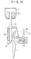
- Reference numeral 1 denotes a sheet representing linen.
- the sheet 1 after being washed and dehydrated, is untangled and spread by a worker, and carried with two adjacent corners being gripped by chucks 2.
- the chuck 2 has a torsion spring 23 (Fig.16), and the sheet 1 is held by being put between a housing 21 and a lever 22.
- a spreader feeder 10 can spread the sheet 1 by moving the two chucks sent through the rail 11 while gripping two corners of the sheet 1 so as to increase the space therebetween.
- the spread feeder 10 is an automatic sheet spreading and carrying device for carrying the sheet 1 only to a roll ironer 3 by a belt conveyor by opening the chucks 2 with the sheet 1 being spread. After releasing the sheet 1, the chucks 2 are recovered automatically in the device, and discharged to a recovery rail 12 (Fig.13).
- the rail 11 carries the chucks 2 gripping the sheet 1 to the spreader feeder 10. If the rail 11 is inclined in the gravity direction, the chuck 2 moves by its weight. If the rail 11 is inclined in the direction opposite to gravity or installed horizontally, the chuck 2 moves by being pushed by a bracket 15 mounted to a chain 16 circulating in the drive rail 13 (Fig. 14). This is similar in effect as a peg run by a conveyor chain that is placed on the top of this peg, as it is the case with a conveyor for linens described in GB-A-2 243 816.
- the recovery rail 12, which carries an empty chuck which has released the sheet 1, has the same construction as that of the rail 11.
- the drive rails 13 and 14 incorporate a resin guide 17 therein, in which the chain 16 circulates.
- the chain 16 is provided with resin bracket 15 at certain intervals to push and move the chuck 2 in the rail 11 and the recovery rail 12.
- the chain 16 is circulated by using a sprocket 18 or the like, and has a gap between the roller and the pin so as to be bent vertically and horizontally.
- the above-described conventional conveyor basically requires three rails for one line as shown in Fig.14: the rail 11 for supplying chucks 2, the drive rail (transport side) 13, and the drive rail (return side) 14. Since the chain 16 and the bracket 15 for the drive system are exposed to the outside of the rail, there is a possibility that the linen is contaminated or damaged in a layout in which the linen is carried at a steep incline or the linen is brought into contact with the rail. There is also a great possibility that foreign matter enters into the chain portion, causing a trouble.
- the stop position in chucking is fixed. Therefore, a worker who secures linen in the chucks sometimes must assume an unnatural posture depending on the body dimensions of the worker, which increases the fatigue of the worker and decreases the work efficiency. Additionally, in the linen supply section, the conveyor sometimes carries the chuck even if the chuck does not grip the linen surely. Therefore, the worker must check for proper gripping of linen after securing the linen in the chuck, and press a supply verification switch.
- the present invention has been made to solve the above problems and is defined in the appendant claims.
- One side edge of a rectangular cloth can be easily gripped. Also, there is no possibility of contaminating the cloth during transfer since the drive section of the clamp is apart from the gripping section of the cloth, and additionally the use of drive belt eliminates the possibility of contamination due to lubricating oil.
- the clamp When the clamp is put on the drive rail, the clamp can be put on the toothed belt at any time at any place in running at the position where the drive starts. Therefore, if this conveyor is employed in a sheet feeder or other apparatus which spread sheets at a high speed, a waste of time is eliminated, greatly improving the handling capacity. Further, the construction of the drive rail is simple, thereby the cost being reduced.
- the wheels supported by the horizontal shafts installed to the clamp body are vertically guided by a pair of opposing rails, and similarly the wheels supported by the vertical shafts are transversely guided by a set of opposite rails. Therefore, the clamp does not strike against or rub the drive conveyor rail or the free conveyor rail.
- the linen supply work can be performed by stopping the linen clamp at a height suitable to the body dimensions of the worker, so that the workability is improved and poor gripping of linen is reduced. As a result, the fatigue of the worker is decreased and the work efficiency is increased. Further, it can be verified that the linen is surely gripped by the clips, thereby the failure in the supply of linen being prevented. The worker need not push the supply verification switch, and the supply of linen is automatically verified. Therefore, the fatigue of the worker is decreased and the work efficiency is increased.
- the gripping of the linen can be detected reliably by two sensors over the entire range of stop position even if a means for changing the stop position of the clamp is provided. If worker's mistake on the supply of linen (gripping by only one clip, improper gripping position of supplied linen, etc.) or defective linen having a stain, contamination, or tear is found, the worker can remove the improper linen easily and surely, thereby the efficiency of the machine being improved.
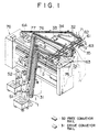
- Fig.1 is a perspective view of a sheet spreading apparatus for washed sheets.
- a sheet 1 is supplied by hands of a worker S1 to an empty clamp 35 (illustrated in detail in Fig.6) having two clips 45 which is sent with a drive conveyor rail 31 (a toothed belt driven by a pulley rotated by a not illustrated drive motor is incorporated). Any corner of the sheet 1 is gripped by the clip 45 on the left side viewed toward the worker and one side including the corner is gripped by the clip 45 on the right side (position A in Fig.1).
- the clamp 35 gripping the sheet 1 rises in the direction of arrow B through the drive conveyor rail 31. At the uppermost point, the clamp 35 transfers to a free conveyor rail 32 inclined slightly downward to lower in the direction of arrow C, and temporarily stops at the position of lower end D.
- a transverse transfer device 61 intermittently transfers clamp cases 62 at certain intervals. When the clamp case 62 stops at position D, it is possible to transfer the clamp 35 from the conveyor rail 32 to the clamp case 62.
- One or a plurality of clamps 35 are pushed into the clamp case 62 by a sequential feeding device (not shown) for feeding the clamp 35 with an air cylinder.
- the transverse transfer device 61 intermittently transfers clamp cases 62.
- the clamp case 62 containing clamps 35 reaches position E and stops there.
- an air cylinder 63 operates to push a clamp girder 42 of the clamp 35 which is in the clamp case 62 and grips the sheet 1 to push out the clamp 35.
- the clamp 35 which has been pushed out is transferred to the drive conveyor rail 31 via a short free conveyor rail 32 to move to an edge setting process.
- the drive conveyor rail 31 to which the clamp 35 has transferred has a toothed belt 34 running inside the rail.
- the toothed belt 34 runs by a pulley which is driven by the drive motor 33.
- the sheet 1 whose any corner and one side including the corner are gripped by two clips 45 of the clamp 35 is brought into contact with a convex front edge 75, spread in width while being subjected to frictional resistance, and pulled in the direction of arrow G when it lowers slantwise from position F of the drive conveyor rail 31.
- the sheet 1 leaves the clip 45 by means of a sheet grip releasing device 64. This action enables the setting of one side edge of the sheet 1.
- the sheet 1 is carried toward the left in the Fig.1 by the flat belt 77 which moves intermittently. In the next process, the whole of sheet 1 is spread on the basis of the sheet side edge which has been set.
- the sheet grip releasing device 64 (Fig.7) at position H in Fig.1 releases the sheet 1.
- the emptied clamp 35 rises slantwise while being driven, and transfers to the free conveyor rail 32 at the uppermost point.
- the clamp 35 is pushed into the clamp case 62 by a sequential feeding device 71 when the position of the clamp case 62 coincides with the free conveyor rail 32.
- the clamp case 62 is carried intermittently, reaching position J, where the clamp 35 is transferred to the free belt conveyor rail 32 and then to the drive conveyor rail 31 by the air cylinder 63.
- the clamp 35 is carried to position A, that is, the position in front of the worker, where the sheet is gripped again.
- the timing of start and stop of driving devices and actuators is determined and the start and stop thereof are effected by the signal of not illustrated various sensors and not illustrated control units.
- the clamping device of the present invention is best suitable for the use in a sheet carrying conveyor device and a sheet edge setting device as describe above. The detailed construction and operation of the clamping device will be described below with reference to Figs.2 through 7.
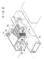
- the drive section of the clamp is constructed as shown in Figs.2 and 3.
- Two pairs of four wheels 39, which rotate in the drive conveyor rail 31, are mounted to shafts 38 fixed to a clamp body 36, and a toothed block 37, which has a plurality of tooth-shaped protrusions to engage with the toothed belt 34 for driving clamps, is installed to the clamp body 36 so that it can be moved downward by the height of the tooth-shaped protrusion.
- the toothed block 37 is disposed so as to straddle over the clamp body 36.
- the toothed block 37 is secured by inserting two pins 40, which are fixed to the clamp body 36, into longitudinally elongated holes 37a, which are drilled in the side walls of the toothed block 37.
- a compression spring 41 which is energized so as to push the toothed block 37 in the engaging direction, is installed between the clamp body 36 and the toothed block 37.
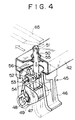
- the clip 45 for gripping the sheet will be described with reference to the perspective view of Fig.4 and the sectional view of Fig.5.
- the clip 45 is constructed so that all moving parts are housed in a clip housing 46.
- a pin 48 is installed to the clip housing 46, and a sheet grip member 47 is supported by the pin 48 so as to rotate freely.
- a torsion spring 49 is wound, which is energized in the direction such that the sheet grip member 47 is pressed against the clip housing 46 to grip the sheet.
- the contact angle between the clip housing 46 and the grip member 47 is set so that when the sheet is once gripped, the gripping force becomes higher as the force of pulling the sheet in the direction in which the weight of the sheet is applied increases.
- a sheet release bar 50 extends over the clip 45 in such a manner that it can be moved vertically.
- a roller 51 is secured to the sheet release bar 50 with a pin, and the lower part of the sheet release bar 50 is connected to an arm 52b of a cam lever 52, which opens/closes the sheet grip member, with a pin 56.
- the cam lever 52 is supported on the clip housing 46 by a pin 53, and energized by a torsion spring 54 so as to raise the sheet release bar 50.
- Another arm 52a of the cam lever 52 engages with a concave portion of the sheet grip member 47.
- the arm 52a pushes a wall 47a of the concave portion of the sheet grip member 47 and turns the sheet grip member 47 to release the sheet gripping portion from the clip housing 46. If the sheet 1 is gripped, it can be released.
- Fig.7 is a perspective view of the sheet grip releasing device 64.
- an actuating lever 66 is supported by a pin 68 of a support 67 mounted on the drive conveyor rail 31, and a cam plate 65 is installed on each side of the actuating lever 66.
- the actuating lever 66 is connected, with a pin, to an air cylinder 69, which is secured to a fixed member 70 with a pin.
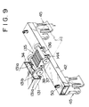
- Figs.8 through 10 show another embodiment of a clamp drive section.
- the drive conveyor rail 131 and the free conveyor rail 132 both have the same shape of rail cross section
- the drive section has a guide for the drive belt.
- the clamp body 136 is provided with two pairs of four wheels secured to shafts 38 fixed to the clamp body 136 so as to rotate freely. These four wheels 39 are guided by the opposing rails 131a of the drive conveyor rail 131. Similarly, two pairs of four wheels 144 are secured to vertical shafts 143 fixed to the clamp body 136 so as to rotate freely. These four wheels 144 are guided by the opposing rails 131b of the drive conveyor rail 131.
- the wheels 39 are guided vertically by the rails 131a, and the wheels 144 are similarly guided transversely by the rails 131b in both the drive conveyor rail 131 and the free conveyor rail 132, so that the clamp 135 does not strike against the drive conveyor rail 131 or the free conveyor rail 132 and stops or rubs it during running.
- the clamp 135 of the present invention when running in the conveyor rail 131, travels while its longitudinal and transverse inclination is controlled with two pairs of wheels 39, which are supported by the horizontal shafts fixed to the clamp body 136, being guided by the rails 131a, which vertically guide the clamp body 136 in the conveyor rail 132.
- two pairs of wheels 144 which rotate horizontally by being supported by the vertical shafts 143, are guided by a set of opposing rails 131b, which transversely guide the clamp body 136 in the conveyor rail 131, so that the clamp 135 travels while being controlled not to move transversely during running.
- Fig.11 shows a supply work height adjusting device at the drive conveyor rail 31 of sheet supply section in accordance with the embodiment of the present invention.
- the empty clamp 35 is lowered slantwise in the direction of arrow A on the drive conveyor rail 31.
- a proximity sensor 82 is installed to detect the passing of the clamp.
- the signal generated by the proximity sensor 82 is sent to a timer 85 having a setting device 86.
- Reference numeral 87 denotes a drive conveyor control device for controlling a not illustrated conveyor drive motor in accordance with the output of the timer 85.
- Reference numeral 80 denotes a safety cover for the worker which covers the sheet supply section installed to the drive conveyor rail 31 by an attaching member 81.
- Fig.11 shows a sheet grip verification device on the drive conveyor rail 31 of the sheet supply section.
- a photoelectric sensors 83 which also have a light source emitting a light beam (x-x) each are installed at the front bent portion of the cover 80.
- a pair of light beam reflectors 84 are installed at the edge of a support plate 80a which is integral with the cover 80.
- the light beam (x-x) runs in parallel to the running direction of the conveyor at a height at which it is intercepted when the sheet is properly gripped by a pair of clips 45 of the sheet holding clamp 35, going and returning back by being reflected by the reflector 84.
- the photoelectric sensors 83 send a signal telling the interception of light beam (x-x) to the drive conveyor control device 87.
- Fig.12 shows a sheet grip releasing device 90 at the sheet supply section.
- a push-button switch 89 for activating the sheet grip releasing device 90 is installed on the cover at a position reached by the worker.
- a cam 93 is supported by a pin 92 fixed to the support body 91 installed to the drive conveyor rail 31 in such a manner so as to rotate freely.
- the cam 93 is operated by an actuating rod of an air cylinder 94 fixed to the support body 91, and pulled up by a tension spring 95.
- a proximity sensor 96 installed to the drive conveyor rail 31 shuts off the electrical circuit for keeping the operation of the cylinder 94 and relieves the air pressure in the cylinder 94 to return the cam 93 to its original position.
- the sheet 1 can be secured to the clamp 35 merely by pushing the corner or the side edge of the sheet 1 between the clip housing 46 and the sheet grip member 47 from the lower side.
- the air cylinder 69 is operated, by which the cam plate 65 lowers in the direction of arrow Y to push the sheet release bar 50, thereby the sheet 1 being released from the clamp 35. Since all moving parts of the clip 45 are housed in the clip housing 46, the troubles of caught or contaminated sheets can be eliminated.
- the sheet 1 can be gripped by spreading only a certain width.
- the sheet 1 secured to the clamp 35 by a worker S2 is handled in the order of A 1 , B 1 , C 1 , D 1 , E, F, G, H, I, J 1 , and A 1 as with the case of the sheet 1 secured by the worker S1.
- the proximity sensor 82 which is installed on the drive conveyor rail 31 running slantwise in the direction of arrow A, detects the passing of the clamp 35
- the timer 85 is activated by the signal from the proximity sensor 82.
- the output signal of the timer 85 sent after a time period set by a setting device 86, the drive conveyor is stopped for supplying the sheet 1.
- the stop position of the clamp 35 that is, the supply height of sheet 1 can be adjusted.
- the restart of conveyor after the supply of sheet 1 is performed by worker's pushing operation of a not illustrated restart switch.
- the edge of the sheet 1 intercepts the light beam (x-x) running between the clips 45, by which the photoelectric sensor 83, which receives the light beam, generates a signal telling the interception of light. Therefore, the gripping of the sheet can be verified.
- This verification signal can be changed into a conveyor start signal. Even if the sheet supply height is changed by the sheet supply height adjusting mechanism as described above, there is no problem because there is a sufficient distance between the photoelectric sensor 83 and the reflector 84.
- the worker can see the sheets which has been supplied just before rising slantwise in the direction of arrow B in front of his/her eyes. If the sheet 1 is incompletely gripped and one clip does not grip the sheet 1, if the corner of sheet is gripped by the reverse one of the clips 45, or if a defect such as a tear is found, the operator pushes the push-button switch 89. By this operation, the excitation circuit of the air pressure cylinder 94 is held, the sheet grip releasing device 90 being activated to protrude the cam 93, so that the clips 45 can release and drop the sheet 1. When the clamp 35 passes through the proximity sensor 96 after passing through the sheet grip releasing device 90, the holding of the excitation circuit of the air pressure cylinder 94 is shut off by the signal of the proximity sensor 96, the original condition being restored.
Landscapes
- Engineering & Computer Science (AREA)
- Textile Engineering (AREA)
- Advancing Webs (AREA)
- Treatment Of Fiber Materials (AREA)
- Feeding Of Articles By Means Other Than Belts Or Rollers (AREA)
Claims (6)
- Convoyeur pour transporter des linges rectangulaires (1), sur lequel les linges sont suspendus sur une attache mobile (35) et soulevés par un convoyeur de transfert d'attache qui comprend une section d'entraînement de l'attache comprenant un corps d'attache (36, 136) et deux paires de galets (39) supportés par des arbres (38) fixés au corps de l'attache (36),
caractérisé en ce que- un coin quelconque et un endroit d'un côté comprenant le coin d'un linge rectangulaire (1) sont saisis entre deux pinces (45) de l'attache mobile (35),- le linge (1) est déplacé en entraînant l'attache (35) le long du convoyeur de transfert sur la surface supérieure d'une table (76) composée d'un convoyeur à bande plate, et tiré sur la table,- l'attache (35) comprend de plus : un bloc denté (37) possédant une pluralité de saillies en forme de dents engrenant avec une courroie dentée (34) entraînant l'attache (35) le long d'un rail de convoyeur (31), le bloc (37) étant monté à cheval au-dessus du corps de l'attache (36) et relié au corps de l'attache par deux broches (40) fixées au corps de l'attache et insérées dans des trous oblongs (37a ) des parois latérales du bloc denté, de façon que le bloc denté (37) puisse être déplacé vers le bas de la hauteur des saillies en forme de dents, et un ressort de compression (41) monté entre le corps de l'attache (36) et le bloc denté (37) qui est comprimé de façon à pousser le bloc denté (37) dans la direction de l'engrènement avec la courroie dentée (34). - Convoyeur pour transporter des linges selon la revendication 1 comprenant : un cadre de pince (46); une broche (48) montée sur le cadre de pince; un organe de saisie de tissu (47) qui est supporté par la broche et peut tourner dans le cadre de pince; un ressort de torsion (49) enroulé autour de la broche (48) exerçant un couple dans la direction de rotation dans laquelle l'organe de saisie de tissu (47) est poussé contre le cadre de pince; une tige de libération de tissu (50) s'étendant au-dessus de l'attache de façon à pouvoir être déplacée verticalement; et un levier-came (52) qui est en prise avec la tige de libération de tissu et ouvre/ferme l'organe de saisie de tissu.
- Convoyeur pour transporter des linges selon la revendication 2 dans lequel une paire de pinces (45) est montée aux deux extrémités d'une traverse (42) montée horizontalement et à angle droit par rapport à la direction de circulation du corps d'attache (36).
- Convoyeur pour transporter des linges selon l'une quelconque des revendications 1 à 3, caractérisé en ce que le convoyeur pour transporter des linges comprend une paire de rails opposés (131a) pour guider verticalement un corps d'attache (136); un ensemble de rails opposés (131b) pour guider transversalement le corps d'attache; une courroie dentée (34) circulant dans un rail de convoyeur (31); un corps d'attache; deux paires de galets (39) qui sont supportés par des arbres horizontaux (38) fixés au corps d'attache (136) et guidés par la paire de rails opposés (131a); et deux paires de galets (144) qui sont supportés par des arbres verticaux (143) fixés au corps d'attache (136) et guidés par l'ensemble de rails opposés (131b).
- Convoyeur pour transporter des linges selon l'une quelconque des revendications 1 à 4 présentant une section d'approvisionnement de linge dans laquelle l'attache (35) est mise sur un rail de convoyeur propulseur (31) du convoyeur de transfert après avoir circulé sur un rail de convoyeur libre incliné (32), descendant en pente, un coin quelconque et un endroit d'un côté comprenant le coin du linge rectangulaire sont saisis par les pinces, puis l'attache (36) est élevée en pente pour suspendre le tissu, le convoyeur de transfert comprenant un dispositif d'ajustement de hauteur de travail d'approvisionnement de linge comprenant : un détecteur de proximité (82) qui est monté à mi-parcours du rail libre (32) du convoyeur de transfert descendant en pente et qui détecte le passage de l'attache (35); une minuterie (85) pourvu d'un dispositif de réglage (86) qui est activé par le signal du détecteur de proximité (82) et peut régler la durée fixée; et des moyens de commande qui arrêtent le convoyeur au moyen du signal de sortie généré après la durée fixée de la minuterie.
- Convoyeur pour transporter des linges selon la revendication 5 comprenant des moyens de vérification de saisie de linge dans lesquels un faisceau lumineux est généré parallèlement à la direction de circulation du convoyeur entre une paire de pinces (45) d'une attache de maintien du linge (35), et des capteurs de lumière (83) pour recevoir le faisceau lumineux sont installés.
Applications Claiming Priority (6)
| Application Number | Priority Date | Filing Date | Title |
|---|---|---|---|
| JP16830992 | 1992-06-04 | ||
| JP168309/92 | 1992-06-04 | ||
| JP333813/92 | 1992-11-20 | ||
| JP33381392A JP3174651B2 (ja) | 1992-11-20 | 1992-11-20 | リネン搬送用コンベヤ |
| JP4337856A JP3029933B2 (ja) | 1992-06-04 | 1992-11-26 | リネン搬送用コンベヤ |
| JP337856/92 | 1992-11-26 |
Publications (2)
| Publication Number | Publication Date |
|---|---|
| EP0573810A1 EP0573810A1 (fr) | 1993-12-15 |
| EP0573810B1 true EP0573810B1 (fr) | 1997-04-09 |
Family
ID=27322978
Family Applications (1)
| Application Number | Title | Priority Date | Filing Date |
|---|---|---|---|
| EP93107895A Expired - Lifetime EP0573810B1 (fr) | 1992-06-04 | 1993-05-14 | Appareil pour le transport de linge |
Country Status (4)
| Country | Link |
|---|---|
| US (1) | US5349768A (fr) |
| EP (1) | EP0573810B1 (fr) |
| DE (1) | DE69309545T2 (fr) |
| DK (1) | DK0573810T3 (fr) |
Families Citing this family (17)
| Publication number | Priority date | Publication date | Assignee | Title |
|---|---|---|---|---|
| DK171332B1 (da) * | 1994-04-28 | 1996-09-09 | Jensen Ejnar & Soen As | Indretning til indfødning af tøjstykker i en ilægger |
| DE19703587A1 (de) * | 1997-01-31 | 1998-08-06 | Kannegiesser H Gmbh Co | Verfahren und Vorrichtung zum Zuführen von Wäschestücken zu einer Mangel |
| US7401426B2 (en) | 2002-06-07 | 2008-07-22 | Jensen Denmark A/S | Method and device for introducing essentially rectangular pieces of cloth into a feeder |
| ES2313099T5 (es) * | 2003-11-18 | 2014-03-20 | Jensen Denmark A/S | Procedimiento y dispositivo para hacer avanzar prendas de ropa esencialmente rectangulares hacia un alimentador |
| DE102007040465B3 (de) | 2007-06-20 | 2009-02-26 | Herbert Kannegiesser Gmbh | Vorrichtung zum Zuführen von Wäschestücken zu einer Wäschebehandlungseinrichtung, insbesondere einer Mangel |
| DE102008021810A1 (de) * | 2007-10-05 | 2009-04-09 | Herbert Kannegiesser Gmbh | Verfahren und Vorrichtung zum Zuführen von Wäschestücken zu einer Wäschebehandlungseinrichtung, insbesondere einer Mangel |
| US7934362B2 (en) * | 2008-03-28 | 2011-05-03 | Cp Packaging, Inc. | Belt driven clamping arrangement for gripping and advancing web material in a packaging machine |
| WO2012163356A1 (fr) * | 2011-05-27 | 2012-12-06 | Jensen Denmark A/S | Procédé et chargeuse pour introduire des pièces de tissu |
| CN103998678B (zh) * | 2011-10-17 | 2016-11-02 | 高达机器人公司 | 用于铺展和装载平状衣物制品的机器 |
| DE102013005251A1 (de) * | 2013-03-27 | 2014-10-02 | Herbert Kannegiesser Gmbh | Verfahren und Vorrichtung zum Transport und/oder Vermessen von Wäschestücken |
| DE102014006697A1 (de) * | 2014-05-09 | 2015-11-12 | Herbert Kannegiesser Gmbh | Klammer für ein Wäschestück |
| US10808352B2 (en) * | 2016-05-05 | 2020-10-20 | Foldimate Inc. | Compact domestic article folding machine with an improved driving mechanism |
| DE102017000171A1 (de) * | 2017-01-12 | 2018-07-12 | Herbert Kannegiesser Gmbh | Verfahren und Vorrichtung zum Transport und/oder Ausbreiten von an Klammern hängenden Wäschestücken |
| JP2021523747A (ja) * | 2018-01-01 | 2021-09-09 | フォールディメイト インコーポレイテッド | 折り畳み機の物品クリップ、物品クリップアセンブリおよび折り畳み機の物品供給方法 |
| JP6999481B2 (ja) * | 2018-04-12 | 2022-01-18 | 株式会社プレックス | 布類掴みチャックおよび布類ハンドリング装置 |
| JP7219025B2 (ja) | 2018-07-05 | 2023-02-07 | 株式会社プレックス | 布類搬送装置 |
| DE102018129561A1 (de) * | 2018-11-23 | 2020-05-28 | Herbert Kannegiesser Gmbh | Verfahren zum Eingeben von Wäschestücken in eine Eingabemaschine |
Family Cites Families (17)
| Publication number | Priority date | Publication date | Assignee | Title |
|---|---|---|---|---|
| US2946427A (en) * | 1958-10-10 | 1960-07-26 | Identification Inc | Garment sorting apparatus |
| FR1550197A (fr) * | 1967-09-08 | 1968-12-20 | ||
| DK137809B (da) * | 1974-09-04 | 1978-05-08 | Beta Sa | Apparat til udspredning af vasketøj og overførsel af dette til en transportør. |
| FR2307907A1 (fr) * | 1975-04-18 | 1976-11-12 | Jean Michel | Preparatrice engageuse pour poser a plat un article souple sur un convoyeur |
| NL167743C (nl) * | 1978-03-09 | 1982-01-18 | Amko Bv | Machine voor het toevoeren en neerleggen van gewassen lakens. |
| DE3320419A1 (de) * | 1983-06-06 | 1984-12-06 | Herbert Kannegiesser Gmbh + Co, 4973 Vlotho | Vorrichtung zum zufuehren von waeschestuecken zu einer mangel oder dgl. |
| BE905687A (nl) * | 1986-10-31 | 1987-02-16 | Werkhuizen Lapauw Bv Met Beper | Insteekmachine voor lakens. |
| ES2005079A6 (es) * | 1986-11-04 | 1989-03-01 | Investronica Sa | Pinza para transportador aereo de pantalones |
| DE3772352D1 (de) * | 1986-12-01 | 1991-09-26 | Mitsubishi Heavy Ind Ltd | Verfahren und vorrichtung zum greifen der ecken eines waeschestuecks. |
| JPH0637247B2 (ja) * | 1986-12-15 | 1994-05-18 | 三菱重工業株式会社 | リネン把持状態の認識方法及び装置 |
| JP2710048B2 (ja) * | 1987-12-03 | 1998-02-10 | ティーディーケイ株式会社 | 垂直磁気記録媒体とその製造方法 |
| DE3839045A1 (de) * | 1988-06-04 | 1989-12-07 | Kannegiesser H Gmbh Co | Verfahren und vorrichtung zum zufuehren von waeschestuecken zu einer mangel |
| FR2632987B1 (fr) * | 1988-06-16 | 1990-10-26 | Robin Francois | Procede de prehension automatisee de deux coins adjacents d'un linge plat et machine correspondante |
| FR2652095B1 (fr) * | 1989-09-19 | 1991-11-29 | Jean Michel Sa | Dispositif de positionnement d'un produit en forme de feuille souple. |
| JPH0649119B2 (ja) * | 1990-04-27 | 1994-06-29 | 株式会社トーカイ | 方形状布類の縁出し装置 |
| DE4014877C2 (de) * | 1990-05-09 | 1993-11-11 | Kannegiesser H Gmbh Co | Vorrichtung zum Zuführen von Wäschestücken zu einer Mangel oder dergleichen |
| JPH0453598A (ja) * | 1990-06-20 | 1992-02-21 | Yozo Maejima | 布類搬送機構に於るワークキャンセル装置 |
-
1993
- 1993-05-14 DK DK93107895.0T patent/DK0573810T3/da active
- 1993-05-14 DE DE69309545T patent/DE69309545T2/de not_active Expired - Fee Related
- 1993-05-14 EP EP93107895A patent/EP0573810B1/fr not_active Expired - Lifetime
- 1993-05-18 US US08/062,554 patent/US5349768A/en not_active Expired - Fee Related
Also Published As
| Publication number | Publication date |
|---|---|
| EP0573810A1 (fr) | 1993-12-15 |
| US5349768A (en) | 1994-09-27 |
| DE69309545T2 (de) | 1997-11-13 |
| DK0573810T3 (da) | 1997-09-22 |
| DE69309545D1 (de) | 1997-05-15 |
Similar Documents
| Publication | Publication Date | Title |
|---|---|---|
| EP0573810B1 (fr) | Appareil pour le transport de linge | |
| US4979868A (en) | Method of gripping corner of strip of cloth | |
| JP3778933B2 (ja) | 平坦な洗濯物供給装置 | |
| KR0133539B1 (ko) | 보드 형태의 워크피스 처리용 장치 | |
| US5430915A (en) | Apparatus for spreading rectangular cloth pieces | |
| JP3839079B2 (ja) | 洗濯物を洗濯物処理装置に送給する方法およびその方法を実施するための装置 | |
| US6883258B2 (en) | Spreader apparatus and method for articles of laundry | |
| JP3029933B2 (ja) | リネン搬送用コンベヤ | |
| ATE224085T1 (de) | Banknotenbearbeitungsmaschine | |
| KR0137639B1 (ko) | 린네르 반송용 컨베이어 | |
| JP3432961B2 (ja) | ワークの機種検出装置 | |
| JP2695739B2 (ja) | 矩形状布片の展開装置 | |
| JP3174651B2 (ja) | リネン搬送用コンベヤ | |
| US6141893A (en) | Laundry feeder method and apparatus | |
| US5823864A (en) | Shellfish transfer device | |
| WO1999014420A1 (fr) | Procede et appareil permettant de saisir et de faire avancer des pieces d'etoffe a partir d'une pile | |
| JPS5974812A (ja) | 部品連続供給装置 | |
| JP3287683B2 (ja) | 葉たばこ自動供給装置 | |
| JP3641544B2 (ja) | 搬送生地の折重ね装置 | |
| JPH0642504B2 (ja) | インナーリードボンダー | |
| JPH04158899A (ja) | 洗濯物の仕上前処理装置 | |
| KR940001806B1 (ko) | Ic 마킹기의 슬리이브 분리 이송장치 | |
| JP2861259B2 (ja) | ハンガー整列装置 | |
| GB2223835A (en) | Drying printed circuit boards | |
| JP2002244304A (ja) | 露光すべき露光面の操作法と操作装置 |
Legal Events
| Date | Code | Title | Description |
|---|---|---|---|
| PUAI | Public reference made under article 153(3) epc to a published international application that has entered the european phase |
Free format text: ORIGINAL CODE: 0009012 |
|
| AK | Designated contracting states |
Kind code of ref document: A1 Designated state(s): DE DK FR GB IT NL |
|
| 17P | Request for examination filed |
Effective date: 19940613 |
|
| 17Q | First examination report despatched |
Effective date: 19960208 |
|
| GRAG | Despatch of communication of intention to grant |
Free format text: ORIGINAL CODE: EPIDOS AGRA |
|
| GRAH | Despatch of communication of intention to grant a patent |
Free format text: ORIGINAL CODE: EPIDOS IGRA |
|
| GRAH | Despatch of communication of intention to grant a patent |
Free format text: ORIGINAL CODE: EPIDOS IGRA |
|
| GRAA | (expected) grant |
Free format text: ORIGINAL CODE: 0009210 |
|
| AK | Designated contracting states |
Kind code of ref document: B1 Designated state(s): DE DK FR GB IT NL |
|
| ITF | It: translation for a ep patent filed | ||
| REF | Corresponds to: |
Ref document number: 69309545 Country of ref document: DE Date of ref document: 19970515 |
|
| ET | Fr: translation filed | ||
| REG | Reference to a national code |
Ref country code: DK Ref legal event code: T3 |
|
| PLBE | No opposition filed within time limit |
Free format text: ORIGINAL CODE: 0009261 |
|
| REG | Reference to a national code |
Ref country code: GB Ref legal event code: 746 Effective date: 19980210 |
|
| 26N | No opposition filed | ||
| PGFP | Annual fee paid to national office [announced via postgrant information from national office to epo] |
Ref country code: GB Payment date: 19980505 Year of fee payment: 6 |
|
| PGFP | Annual fee paid to national office [announced via postgrant information from national office to epo] |
Ref country code: FR Payment date: 19980511 Year of fee payment: 6 |
|
| PGFP | Annual fee paid to national office [announced via postgrant information from national office to epo] |
Ref country code: DK Payment date: 19980515 Year of fee payment: 6 |
|
| REG | Reference to a national code |
Ref country code: FR Ref legal event code: D6 |
|
| PG25 | Lapsed in a contracting state [announced via postgrant information from national office to epo] |
Ref country code: GB Free format text: LAPSE BECAUSE OF NON-PAYMENT OF DUE FEES Effective date: 19990514 |
|
| PG25 | Lapsed in a contracting state [announced via postgrant information from national office to epo] |
Ref country code: DK Free format text: LAPSE BECAUSE OF NON-PAYMENT OF DUE FEES Effective date: 19990531 |
|
| GBPC | Gb: european patent ceased through non-payment of renewal fee |
Effective date: 19990514 |
|
| PG25 | Lapsed in a contracting state [announced via postgrant information from national office to epo] |
Ref country code: FR Free format text: LAPSE BECAUSE OF NON-PAYMENT OF DUE FEES Effective date: 20000131 |
|
| REG | Reference to a national code |
Ref country code: FR Ref legal event code: ST |
|
| REG | Reference to a national code |
Ref country code: DK Ref legal event code: EBP |
|
| PGFP | Annual fee paid to national office [announced via postgrant information from national office to epo] |
Ref country code: DE Payment date: 20010508 Year of fee payment: 9 |
|
| PGFP | Annual fee paid to national office [announced via postgrant information from national office to epo] |
Ref country code: NL Payment date: 20010531 Year of fee payment: 9 |
|
| PG25 | Lapsed in a contracting state [announced via postgrant information from national office to epo] |
Ref country code: NL Free format text: LAPSE BECAUSE OF NON-PAYMENT OF DUE FEES Effective date: 20021201 |
|
| PG25 | Lapsed in a contracting state [announced via postgrant information from national office to epo] |
Ref country code: DE Free format text: LAPSE BECAUSE OF NON-PAYMENT OF DUE FEES Effective date: 20021203 |
|
| NLV4 | Nl: lapsed or anulled due to non-payment of the annual fee |
Effective date: 20021201 |
|
| PG25 | Lapsed in a contracting state [announced via postgrant information from national office to epo] |
Ref country code: IT Free format text: LAPSE BECAUSE OF NON-PAYMENT OF DUE FEES Effective date: 20050514 |