EP0574014B1 - Vorrichtung zum Biegen von Messerband - Google Patents
Vorrichtung zum Biegen von Messerband Download PDFInfo
- Publication number
- EP0574014B1 EP0574014B1 EP93109406A EP93109406A EP0574014B1 EP 0574014 B1 EP0574014 B1 EP 0574014B1 EP 93109406 A EP93109406 A EP 93109406A EP 93109406 A EP93109406 A EP 93109406A EP 0574014 B1 EP0574014 B1 EP 0574014B1
- Authority
- EP
- European Patent Office
- Prior art keywords
- knife
- bending
- blank
- feed
- knife blank
- Prior art date
- Legal status (The legal status is an assumption and is not a legal conclusion. Google has not performed a legal analysis and makes no representation as to the accuracy of the status listed.)
- Expired - Lifetime
Links
- 238000005452 bending Methods 0.000 title claims description 129
- 238000004146 energy storage Methods 0.000 claims 2
- 238000000034 method Methods 0.000 description 14
- 239000000463 material Substances 0.000 description 5
- 230000000717 retained effect Effects 0.000 description 3
- 238000010276 construction Methods 0.000 description 2
- 238000005520 cutting process Methods 0.000 description 2
- 230000003247 decreasing effect Effects 0.000 description 2
- 230000005489 elastic deformation Effects 0.000 description 2
- 238000003780 insertion Methods 0.000 description 2
- 230000037431 insertion Effects 0.000 description 2
- 238000003825 pressing Methods 0.000 description 2
- 238000010008 shearing Methods 0.000 description 2
- 125000006850 spacer group Chemical group 0.000 description 2
- 230000001276 controlling effect Effects 0.000 description 1
- 238000003754 machining Methods 0.000 description 1
- 239000002985 plastic film Substances 0.000 description 1
- 230000001105 regulatory effect Effects 0.000 description 1
Images




Classifications
-
- B—PERFORMING OPERATIONS; TRANSPORTING
- B21—MECHANICAL METAL-WORKING WITHOUT ESSENTIALLY REMOVING MATERIAL; PUNCHING METAL
- B21D—WORKING OR PROCESSING OF SHEET METAL OR METAL TUBES, RODS OR PROFILES WITHOUT ESSENTIALLY REMOVING MATERIAL; PUNCHING METAL
- B21D53/00—Making other particular articles
- B21D53/60—Making other particular articles cutlery wares; garden tools or the like
- B21D53/64—Making other particular articles cutlery wares; garden tools or the like knives; scissors; cutting blades
-
- B—PERFORMING OPERATIONS; TRANSPORTING
- B21—MECHANICAL METAL-WORKING WITHOUT ESSENTIALLY REMOVING MATERIAL; PUNCHING METAL
- B21D—WORKING OR PROCESSING OF SHEET METAL OR METAL TUBES, RODS OR PROFILES WITHOUT ESSENTIALLY REMOVING MATERIAL; PUNCHING METAL
- B21D11/00—Bending not restricted to forms of material mentioned in only one of groups B21D5/00, B21D7/00, B21D9/00; Bending not provided for in groups B21D5/00 - B21D9/00; Twisting
- B21D11/10—Bending specially adapted to produce specific articles, e.g. leaf springs
Definitions
- the present invention relates to a knife bending apparatus according to the preamble of claim 1, which is used for die cutting and creasing such sheet-like materials as paper, plastic sheets, corrugated paper, etc to a specified shape by die cut pressing etc.
- this kind of knife “A” is like a thin band (for example, the thickness is 0.4mm to 1.0mm), has a blade edge 1 and is formed so that the section thereof is roughly rectangular. And, during use, the knife “A” is fitted and fixed in a knife insertion groove 3 which has been pierced and consecutively formed on a wooden knife retainer block 2.
- the knife insertion groove 3 has been formed in advance to a required shape (shape corresponding to a die cut shape) by, for example, laser beam machining.
- a required shape shape corresponding to a die cut shape
- the back 6 side thereof is placed along a surface plate, not shown, and at the same time is put and pressed with a set of bending die from both the sides of the knife "A", thereby causing a specified bending portion 5 to be formed.
- a knife bending apparatus according to the preamble of claim 1 is known from EP-A-0 317 637.
- the present invention has been developed in view of the above situations, and it is an object of the invention to provide a bending apparatus which can very efficiently bend the knife so that an accurate bending angle for the back thereof can be obtained by making the back of the knife run along on a surface plate.
- elongation of a knife material in line with the elastic deformation in the bending process can be preferably absorbed at the bending portion, and the knife is bent to an accurate bending angle without shearing, with reference to the upper face of the surface plate.
- the springback phenomenon for the knife can be preferably suppressed, and it is possible to remarkably efficiently carry out bending processes to a specified shape.
- the knife back is made to run along on the surface plate, the springback phenomenon is preferably suppressed so that an accurate bending angle for the back can be obtained, and it is possible to very efficiently work or bend the knife.
- the bending mechanism can stay at the position, where the bending mechanism operates on the knife, for a specified period of time, the springback phenomenon for the knife can be preferably suppressed, and the bending process is remarkably efficient.
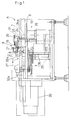
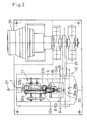
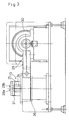
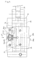
- a bending apparatus in accordance with the preferred embodiment comprises a supporting mechanism 8 to slidably support a knife “A" from both its sides in such a state that the back 6 (one end side in its lengthwise direction) of the knife “A” is made to run along the upper face of a surface plate 7, a biasing mechanism 9 to bias the knife “A” toward the upper face of the surface plate 7, a bending mechanism 10 to be placed adjacent to the supporting mechanism 8 with a specified clearance "t" (See FIG.4) and to repeatedly give a bending force to the knife “A” which is supported by the supporting mechanism 8, a feed mechanism 11 to feed the knife “A” from the supporting mechanism 8 every time when bending process is carried out by the bending mechanism 10, and a control device 39 to change the bending action amount of a bending die 24 of the bending mechanism 10 for the knife "A” and/or the feed amount of the knife “A” by the feed mechanism 11.
- the supporting mechanism 8 is provided with a block 12 having a groove to receive the knife "A” and the clearance "t” between a spacer 13 attached to the front face of the block 12 and the bending mechanism 10 can be adjusted by properly changing the spacer 13.
- the biasing mechanism 9 is arrayed opposite to the upper face of the surface plate 7 and consists of a press roller device which presses the knife "A" onto the upper face of the surface plate 7.
- the press roller device defines a supporting groove 15a to fit and insert the blade edge 1 of the knife "A" to the circumferential face of a roller 15 which is rotatably supported by a shaft 14 and to support the tapered face thereof.
- the shaft 14 is rockably supported by a supporting shaft 16 against the upper face of the surface plate 7, and at the same time is elastically biased toward the upper face by a spring 17 which is an example of an energy-charging means.
- a long slit 18a is pierced and formed in the lengthwise direction of a bracket 18 which supports the roller 15, and the support shaft 16 attached to a bracket 19 is slidably inserted into the long slit 18a.
- the bracket 19 is provided with an operating lever 20, and the bracket 19 is slidably supported by a bracket 21 attached to the bending apparatus body in the same direction as the lengthwise direction of the long slit 18a of the bracket 18.
- the spring 17 intervenes between the position corresponding to the intermediate portion pertaining to the lengthwise direction of the long slit 18a on the bracket 18 and the bracket 21.
- the supporting shaft 16 moves to the position shown with a broken line in FIG. 9A, and the roller 15 is biased toward the upper face of the surface plate 7 with an elastic energy charged in the spring 17.
- the bracket 19 is made to move in the direction of the arrow 22b by operating the lever 20, the supporting shaft 16 will move to the position shown with a solid line in FIG. 9A, and the roller 15 will be rockably biased upwards by the action of the spring 17.
- the rocking position is regulated by a stopper 23.
- the press roller device relatively varies the position of the supporting shaft 16 relative to the position determined by the biasing force of the spring 17, thereby causing the direction in which the roller 15 is biased relative to the upper face of the surface plate 7 to be properly selectively changed.
- the press roller device it is possible to press the knife “A” onto the surface plate 7 without damaging the blade edge 1 of the knife “A” and to retain it without fail, and at the same time the press roller device can properly correspond to changes in the height of the knife "A". Furthermore, it is very easy to change the retaining state and the releasing state relative to the knife "A” only by simply operating the lever 20 in the forward and backward direction.
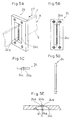
- the bending apparatus 10 is composed of the bending die 24 (See FIG. 5) for bending the knife “A” through operating on the side of the knife "A".
- the bending die 24 is composed of a thin plate-like member, and roughly at the middle portion thereof, a groove 24b provided with an edge portion 24a, which will become parallel to both the sides of the knife “A” when the knife "A” passes therethrough with a proper clearance, is formed by, for example, a wire cutting process.
- the edge portions 24a are hardened.
- the abovementioned proper clearance is of such a dimension that one edge portion 24a can be brought into contact with either side (the side opposite to the direction along which the knife "A" is about to be bent) of the knife "A" when the bending die 24 is vibrated as described later. Namely, it is of such a dimension that both the edge portions 24a are not brought into contact with both the side portions of the knife "A” in line with the vibrations of the bending die 24.
- An arcuate circumferential face 24c defined by a curvature radius R is inscribed at the front side of the bending die 24 for the purpose of easy transit of the knife "A" after it has been bent.
- the bending die 24 composed as stated above is removably fitted in a base 25 (See FIG. 6) equivalent to a holder and is retained with screws at its upper and lower parts.
- a base 25 See FIG. 6
- the lower end portion thereof is slidably supported by a slide bearing 26, linearly as illustrated, in the right angle direction (the direction of the arrows 28a and 28b) relative to the feed direction (the direction of the arrow 27) of the knife "A".
- the base 25 is vibrated and driven, along with the bending die 24, in the bending direction of the knife "A" by a motor 30 which is controlled through a crank 29 by the control device 39.
- the upper part of the base 25 is supported at the L-shaped end of a supporting member 31 which is formed to be roughly L-shaped.
- the base 25 is slidable in the right and the left directions (the directions of the arrows 28a and 28b) relative to the supporting member 31.
- the bending die 24 being composed as stated above, as the groove 24b is formed as described above, the parallelism of the edge portions 24a relative to the side of the knife “A” can be secured, and a bending process can be carried out, with accurate rectangularity obtained, without such an inconvenience as a warping caused to be present in the knife "A". Besides, because the bending die 24 is formed to be thin, it is possible to carry out bending processes of comparatively small curvature radius for the knife "A".
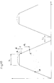
- Figure 10 is a graph showing the action of the bending die versus the time T.
- Position A represents the position in which the die starts contacting a knife.
- Position B represents the position in which the die starts parting from the knife.
- Position C represents the position in which the die starts parting from the knife in a conventional apparatus.
- the distances d1 and d2 represent springback amounts.
- the bending die 24 is controlled by a control device 39 so that it can stay, for a specified pressing time (the period of staying time: the period of stopping time in such a state that the bending die 24 is in contact with the side of the knife "A") T 1 , at the position operating on the knife "A", the springback amount on the knife “A” will be substantially decreased more than in any conventional apparatus, thereby causing a remarkably efficient bending process to be carried out. That is, the number of times of bringing the bending die 24 into contact with the side of the knife "A" can be much decreased.
- the staying time T 1 is about 0.3 to 0.4 seconds.
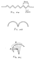
- the control device 39 is concurrently provided with a function to change the bending action amount relative to the knife "A" in the vibration actions of the bending die 24 and the feed amount of the knife “A” by the feed mechanism 11, for example, whenever carrying out bending processes. Therefore, in the apparatus, it is possible to work the knife “A” to various shapes, for example, bellows, arcuate or spiral shape, etc. (See Figures 11a, b and c).
- segment A is a circular arc, the bending of which is achieved by repeatedly feeding the knife over a constant distance. Segment B is obtained by feeding the knife over variable distances.
- the bending die 24 is actuated at a constant bending action amount as the knife “A” is sent out repeatedly three to five times by a pitch of 0.5mm at every bending process. It is thereby possible to simply bend the knife "A” to a circular arc shape of small radius with high accuracy.
- the knife "A” can be formed to be like a vortex in its plan view by gradually increasing the feed amount by the feed mechanism 11. Simultaneously, the bending amount of the bending die 24 may be gradually changed.
- the knife “A” is bent by 90° in its plan view
- the knife “A” is bent by 45° by the bending die 24 in the first bending process.
- the knife “A” is fed by 0.5mm by the feed mechanism 11, and it is further bent by 45° by the bending die 24. Then, the knife “A” is thereby bent by almost 90° visually.
- the base 25 is provided at the upper part of the retaining position of the bending die 24, with screws 37 and 38 for micro adjustment of the inclination degree (the inclination angle in the directions of the arrows 28a, 28b in connection with the upper face of the surface plate 7) of the bending die 24 in its right and left directions.
- the screws 37, 38 are properly adjusted to incline the bending die 24 relative to the surface plate 7.
- the knife "A” is given a distributary force in the direction along which it is pressed down toward the upper face of the surface plate 7.
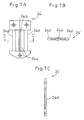
- FIG. 7 shows a bending die 24' according to another preferred embodiment.
- notches 24d, 24d are formed at both sides of the edge part 24a, putting it therebetween.
- the feed mechanism 11 is provided with a plurality of rollers 32a, 32b, 33a, 33b, 34a, 34b so that the knife "A" is held from both its sides and is fed in the direction of the arrow 27.
- Each of these rollers is driven synchronously by a motor 36 through an interlocking mechanism 35 consisting of a plurality of belts, pulleys, etc.
- the rollers 32b, 33b properly correspond to the thickness of the knife "A" and are supported so that their position relative to the knife “A” can be changed, thereby causing the rollers 32b, 33b to be elastically biased in the direction of the arrow 28b at all times.
- the motor 36 is controlled synchronously with the motor 30.
- a knife "A” is retained by the supporting mechanism 8 and the biasing mechanism 9, relative to the upper face of the surface plate 7.
- the knife "A” which is retained as shown above will be bent by the bending mechanism 10.
- the base 25 is vibrated and driven by the motor 30 so that one edge portion 24a of the groove 24b of a bending die 24 comes in contact with the knife side opposite to the direction along which the knife "A" is about to be bent.
- the edge part 24a whose parallelism is secured relative to the knife “A” side is vibrated and driven linearly, repeating a specified staying time T 1 and knife “A” sending time T 2 by turns, with the edge part 24a vertically standing in connection with the surface plate 7, the knife "A" will be bent with an accurate rectangularity obtained.
- the knife “A” is fed from the supporting mechanism 8 by the feed mechanism 11 and is bent to a specified curvature radius.
- the knife "A" can be sheared with an accurate rectangularity at a specified dimension.
Landscapes
- Engineering & Computer Science (AREA)
- Mechanical Engineering (AREA)
- Bending Of Plates, Rods, And Pipes (AREA)
Claims (8)
- Klingenbiegevorrichtung zum Biegen eines langen und dünnen plattenförmigen Klingenrohlings zu einer Bandklinge, versehen mit:einem Stützmechanismus (8), um den Klingenrohling (A) an dessen beiden flachen Seiten mittels einer Aufnahmenut gleitend abzustützen, wobei eine der Längskanten des Klingenrohlings von der Oberseite einer Stützplatte (7) abgestützt wird und die Aufnahmenut in einer Ebene senkrecht zu der Längsrichtung des Rohlings von dem Stützmechanismus bestimmt ist,einem benachbart dem Stützmechanismus (8) in einer Richtung stromab in einem vorbestimmten Abstand (t) angeordneten Biegemechanismus (10), undeinem Fördermechanismus (11) zum Fördern des Klingenrohlings (A) relativ zu dem Stützmechanismus (8),wobei der Fördermechanismus (11) ausgebildet ist, den Klingenrohling (A) intermittierend um vorbestimmte Strecken zu fördern,wobei der Biegemechanismus betätigt wird, um nach jedem Förderzyklus eine Biegekraft in einer Richtung senkrecht zu der Förderebene des Klingenrohlings (A) auf den Klingenrohling (A) aufzubringen, undwobei der Biegemechanismus ein Biegebauteil aufweist, das senkrecht zu der Förderrichtung des Klingenrohlings (A) ausgerichtet ist, wobei das Biegebauteil so vorgesehen ist, daß mindestens ein Randbereich parallel zu der Förderebene des Klingenrohlings verläuft, und es in einer Richtung senkrecht zu der Förderebene des Klingenrohlings (A) bewegbar ist;
gekennzeichnet durcheinen Vorspannmechanismus (9), welcher den Klingenrohling (A) elastisch gegen die Oberseite der Stützplatte (7) anpreßt, versehen mit einer Anpreßwalze (15) mit einer im Umfang verlaufenden Nut (15a) zum Einfügen und Einführen einer der Kanten (1), um den Klingenrohling zwischen der Anpreßwalze (15) und der Oberseite der Stützplatte (7) einzuklemmen. - Klingenbiegevorrichtung nach Anspruch 1, versehen mit einer Steuervorrichtung (39) zum Ändern des Betrages der mittels des Biegemechanismus (10) auf den Klingenrohling (A) aufgebrachten Biegewirkung.
- Klingenbiegevorrichtung nach Anspruch 1 oder 2, versehen mit einer Steuervorrichtung (39) zum Ändern des Betrages der mittels des Fördermechanismus (11) auf den Klingenrohling (A) aufgebrachten Förderwirkung.
- Klingenbiegevorrichtung nach Anspruch 1, versehen mit einer Steuervorrichtung (39), um die Verweildauer des Biegemechanismus (10) in dessen Arbeitsposition für den Klingenrohling (A) während der Zeitdauer vom Beginn des Biegens der Klinge bis zu dessen Beendigung durch den Biegemechanismus auf einen bestimmten Wert einzustellen und um bei einem entsprechenden Zeitintervall einen wiederholten Biegebetrieb des Biegemechanismus auszulösen.
- Klingenbiegevorrichtung nach einem der vorhergehenden Ansprüche, wobei die Nut (15a) in der Umfangsfläche der Walze (15) verläuft, wobei der Klingenrücken entlang der Oberseite der Stützplatte (7) entlangläuft, wobei die Nut (15a) die sich verjüngende Stirnseite der Klingenkante abstützt, und wobei die Walze (15) schwenkbar von einer Stützwelle (16) getragen ist, wobei auf die Walze (15) von einer Energiespeicheranordnung (17) Energie in Richtung auf die Oberseite der Stützplatte (7) aufgebracht wird.
- Klingenbiegevorrichtung nach Anspruch 5, wobei die Stützposition der Walze (15) durch die Stützwalze (16) in Bezug auf die Position der Energiespeicheranordnung (17) zum Aufbringen von Energie relativ variabel ist, um so die Richtung, in welche die Walze (15) mit Bezug auf die Oberseite der Stützplatte (7) vorgespannt wird, selektiv zu ändern.
- Klingenbiegevorrichtung nach einem der vorhergehenden Ansprüche, wobei das Biegebauteil ein Biegestempel (24, 24') ist, der aus einem plattenförmigen Bauteil aufgebaut ist, das näherungsweise in dessen Mittelbereich mit einem Schlitz (24b) versehen ist, der über einen Randbereich (24a) verfügt, der zu den beiden flachen Seiten des Klingenrohlings (A) parallel verläuft, wenn der Klingenrohling diesen mit einem angemesenenen Freiraum passiert.
- Klingenbiegevorrichtung nach Anspruch 7, wobei eine Ende des Biegestempels (24, 24') mit einem Antriebsmechanismus (29, 30) gekoppelt ist, der den Biegestempel in einer Richtung senkrecht zur Förderebene des Klingenrohlings (A) hin- und herbewegt, wobei das andere Ende des Biegestempels von einem Stützteil (31) getragen ist, welches ein Verkippen des Biegestempels senkrecht zu der Richtung verhindert, in welcher der Biegestempel von dem Antriebsmechanuismus bewegt wird.
Applications Claiming Priority (4)
| Application Number | Priority Date | Filing Date | Title |
|---|---|---|---|
| JP4151874A JPH07108413B2 (ja) | 1992-06-11 | 1992-06-11 | ナイフの曲げ加工装置 |
| JP151874/92 | 1992-06-11 | ||
| JP5001987A JP2735452B2 (ja) | 1993-01-08 | 1993-01-08 | ナイフの曲げ加工装置 |
| JP1987/93 | 1993-01-08 |
Publications (2)
| Publication Number | Publication Date |
|---|---|
| EP0574014A1 EP0574014A1 (de) | 1993-12-15 |
| EP0574014B1 true EP0574014B1 (de) | 1997-09-10 |
Family
ID=26335294
Family Applications (1)
| Application Number | Title | Priority Date | Filing Date |
|---|---|---|---|
| EP93109406A Expired - Lifetime EP0574014B1 (de) | 1992-06-11 | 1993-06-11 | Vorrichtung zum Biegen von Messerband |
Country Status (3)
| Country | Link |
|---|---|
| US (1) | US5481896A (de) |
| EP (1) | EP0574014B1 (de) |
| DE (1) | DE69313727T2 (de) |
Families Citing this family (1)
| Publication number | Priority date | Publication date | Assignee | Title |
|---|---|---|---|---|
| KR0182069B1 (ko) * | 1995-06-22 | 1999-04-01 | 송병준 | 컷팅블레이드의 절곡시스템 |
Family Cites Families (10)
| Publication number | Priority date | Publication date | Assignee | Title |
|---|---|---|---|---|
| FR1457447A (fr) * | 1965-08-06 | 1966-01-24 | Machine à cintrer les tôles | |
| AT322323B (de) * | 1972-01-04 | 1975-05-12 | Skomab Internat Maschinen Und | Biegevorrichtung für stanzmesser |
| JPS56102319A (en) * | 1980-01-21 | 1981-08-15 | Inoue Mtp Co Ltd | Method and apparatus for bending long sized material |
| FR2502518A1 (fr) * | 1981-03-26 | 1982-10-01 | Favrin Pierre | Machine pour le pliage de toles en aller et retour sur plieuse |
| GB2116086B (en) * | 1982-03-04 | 1985-11-27 | Pa Management Consult | Making cutting tool |
| FR2535629A1 (fr) * | 1982-11-08 | 1984-05-11 | Autocoussin Sa | Machine automatique pour cambrer selon une configuration spatiale, des elements metalliques minces et rectilignes, et notamment des fils metalliques |
| JPS62248527A (ja) * | 1986-04-22 | 1987-10-29 | Shinsei Kogyo Kk | 曲げ加工装置 |
| JPH0661583B2 (ja) * | 1987-06-10 | 1994-08-17 | 末弘 水河 | 帯刃の曲げ加工方法 |
| US5259231A (en) * | 1989-10-26 | 1993-11-09 | Reinhardt Maschinenbau Gmbh | Process for the two-directional bending of sheet metal |
| ATE100002T1 (de) * | 1990-06-07 | 1994-01-15 | Peter Lisec | Verfahren und vorrichtung zum biegen von hohlprofilleisten zu abstandhalterrahmen fuer isolierglasscheiben. |
-
1993
- 1993-06-11 EP EP93109406A patent/EP0574014B1/de not_active Expired - Lifetime
- 1993-06-11 US US08/074,544 patent/US5481896A/en not_active Expired - Fee Related
- 1993-06-11 DE DE69313727T patent/DE69313727T2/de not_active Expired - Fee Related
Also Published As
| Publication number | Publication date |
|---|---|
| DE69313727D1 (de) | 1997-10-16 |
| DE69313727T2 (de) | 1998-03-19 |
| EP0574014A1 (de) | 1993-12-15 |
| US5481896A (en) | 1996-01-09 |
Similar Documents
| Publication | Publication Date | Title |
|---|---|---|
| US4383458A (en) | Film cutter | |
| US5584218A (en) | Cutter having a pair of cooperating flexible blades providing a pair of moving point cutting edges | |
| US20090013747A1 (en) | Channel Letter Machine and Method Thereof | |
| EP1157760A2 (de) | Biegevorrichtung für schneidmesser | |
| US6367302B1 (en) | Method for bending and cutting metal strip material | |
| EP1102648B1 (de) | Vorrichtung zum formen von schneidplatten für drucksachen | |
| US5481896A (en) | Knife bending apparatus | |
| US6634267B1 (en) | Apparatus and method for removing fasteners from documents | |
| CN222359156U (zh) | 拉料机构及冲压设备 | |
| JPH072100Y2 (ja) | ナイフ加工用ダイスの支持構造 | |
| JP2735452B2 (ja) | ナイフの曲げ加工装置 | |
| JPH072099Y2 (ja) | 押えローラ装置 | |
| JPH06234017A (ja) | ナイフの曲げ加工装置 | |
| JPH07108412B2 (ja) | ナイフの曲げ加工装置 | |
| JPH07108411B2 (ja) | ナイフの加工用ダイス | |
| JP3282720B2 (ja) | ナイフの曲げ加工装置 | |
| JPH0698421B2 (ja) | ナイフの曲げ加工装置 | |
| GB2154924A (en) | Cutting mechanism | |
| US6324953B1 (en) | Device for forming cutting blade for prints | |
| JPH0647698A (ja) | シート材をプロット、切断そして/又はパンチングする装置 | |
| EP1236528B1 (de) | Schneidvorrichtung zur Herstellung von Schneidmessern | |
| JP3529448B2 (ja) | 切断型 | |
| JPH0715746Y2 (ja) | 紙切断装置 | |
| JPS5815065Y2 (ja) | 帯状薄板の連続切断装置 | |
| JPH06238337A (ja) | ナイフの曲げ加工装置 |
Legal Events
| Date | Code | Title | Description |
|---|---|---|---|
| PUAI | Public reference made under article 153(3) epc to a published international application that has entered the european phase |
Free format text: ORIGINAL CODE: 0009012 |
|
| 17P | Request for examination filed |
Effective date: 19930708 |
|
| AK | Designated contracting states |
Kind code of ref document: A1 Designated state(s): DE FR GB SE |
|
| 17Q | First examination report despatched |
Effective date: 19950309 |
|
| GRAG | Despatch of communication of intention to grant |
Free format text: ORIGINAL CODE: EPIDOS AGRA |
|
| GRAH | Despatch of communication of intention to grant a patent |
Free format text: ORIGINAL CODE: EPIDOS IGRA |
|
| GRAH | Despatch of communication of intention to grant a patent |
Free format text: ORIGINAL CODE: EPIDOS IGRA |
|
| GRAA | (expected) grant |
Free format text: ORIGINAL CODE: 0009210 |
|
| AK | Designated contracting states |
Kind code of ref document: B1 Designated state(s): DE FR GB SE |
|
| REF | Corresponds to: |
Ref document number: 69313727 Country of ref document: DE Date of ref document: 19971016 |
|
| ET | Fr: translation filed | ||
| PLBE | No opposition filed within time limit |
Free format text: ORIGINAL CODE: 0009261 |
|
| STAA | Information on the status of an ep patent application or granted ep patent |
Free format text: STATUS: NO OPPOSITION FILED WITHIN TIME LIMIT |
|
| 26N | No opposition filed | ||
| REG | Reference to a national code |
Ref country code: GB Ref legal event code: IF02 |
|
| PGFP | Annual fee paid to national office [announced via postgrant information from national office to epo] |
Ref country code: FR Payment date: 20020523 Year of fee payment: 10 |
|
| PGFP | Annual fee paid to national office [announced via postgrant information from national office to epo] |
Ref country code: SE Payment date: 20020524 Year of fee payment: 10 |
|
| PGFP | Annual fee paid to national office [announced via postgrant information from national office to epo] |
Ref country code: GB Payment date: 20020606 Year of fee payment: 10 |
|
| PGFP | Annual fee paid to national office [announced via postgrant information from national office to epo] |
Ref country code: DE Payment date: 20020629 Year of fee payment: 10 |
|
| PG25 | Lapsed in a contracting state [announced via postgrant information from national office to epo] |
Ref country code: GB Free format text: LAPSE BECAUSE OF NON-PAYMENT OF DUE FEES Effective date: 20030611 |
|
| PG25 | Lapsed in a contracting state [announced via postgrant information from national office to epo] |
Ref country code: SE Free format text: LAPSE BECAUSE OF NON-PAYMENT OF DUE FEES Effective date: 20030612 |
|
| PG25 | Lapsed in a contracting state [announced via postgrant information from national office to epo] |
Ref country code: DE Free format text: LAPSE BECAUSE OF NON-PAYMENT OF DUE FEES Effective date: 20040101 |
|
| GBPC | Gb: european patent ceased through non-payment of renewal fee |
Effective date: 20030611 |
|
| EUG | Se: european patent has lapsed | ||
| PG25 | Lapsed in a contracting state [announced via postgrant information from national office to epo] |
Ref country code: FR Free format text: LAPSE BECAUSE OF NON-PAYMENT OF DUE FEES Effective date: 20040227 |
|
| REG | Reference to a national code |
Ref country code: FR Ref legal event code: ST |