EP0574613A1 - Fahrradrahmen - Google Patents
Fahrradrahmen Download PDFInfo
- Publication number
- EP0574613A1 EP0574613A1 EP92120407A EP92120407A EP0574613A1 EP 0574613 A1 EP0574613 A1 EP 0574613A1 EP 92120407 A EP92120407 A EP 92120407A EP 92120407 A EP92120407 A EP 92120407A EP 0574613 A1 EP0574613 A1 EP 0574613A1
- Authority
- EP
- European Patent Office
- Prior art keywords
- apex
- pivotally connected
- lug
- cylinder
- seat
- Prior art date
- Legal status (The legal status is an assumption and is not a legal conclusion. Google has not performed a legal analysis and makes no representation as to the accuracy of the status listed.)
- Granted
Links
Images


Classifications
-
- B—PERFORMING OPERATIONS; TRANSPORTING
- B62—LAND VEHICLES FOR TRAVELLING OTHERWISE THAN ON RAILS
- B62K—CYCLES; CYCLE FRAMES; CYCLE STEERING DEVICES; RIDER-OPERATED TERMINAL CONTROLS SPECIALLY ADAPTED FOR CYCLES; CYCLE AXLE SUSPENSIONS; CYCLE SIDECARS, FORECARS, OR THE LIKE
- B62K25/00—Axle suspensions
- B62K25/04—Axle suspensions for mounting axles resiliently on cycle frame or fork
- B62K25/28—Axle suspensions for mounting axles resiliently on cycle frame or fork with pivoted chain-stay
- B62K25/286—Axle suspensions for mounting axles resiliently on cycle frame or fork with pivoted chain-stay the shock absorber being connected to the chain-stay via a linkage mechanism
Definitions
- the present invention relates to an improvement in a bicycle frame and, more particularly, to a bicycle frame which can absorb shocks during running to provide a more comfortable ride and which exhibits improved durability and running performance, thus attaining improved safety of ride.
- a bicycle has been designed in such a way that impact is eased by a front fork which is bent in response to any shock to absorb it. Because the provision of a suspension system has been considered to be incompatible with the basic requirements for making a bicycle lighter and more rigid, the suspension system has not been employed so far. Recently, however, the bicycle materials have been made lighter and, in addition, more comfortable ride is greatly demanded. According to the remarkable popularity of mountain bicycles (MTB), moreover, various kinds of bicycle races have become popular, including offroad and downhill rides. Thus, to absorb shock caused by rough roads is greatly demanded.
- MTB mountain bicycles
- the present invention provides an improvement in a bicycle frame of the type that has a bracket lug, a seat lug and a head lug, the bracket, seat and head lugs being linked together by a seat tube, an upper tube and a lower tube to form a substantially triangular frame structure.
- the improvement according to the present invention comprises a chain stay disposed rearwardly of the triangular frame structure and pivotally connected at an end to the bracket lug; a substantially triangular link having a first apex formed between its long and short sides, a second apex formed between the long side and a medium side and a third apex formed between the medium and short sides, the link being pivotally connected at a point adjacent the first apex to the seat lug such that the long side is directed toward the head lug; a shock absorbing cylinder assembly including a cylinder connected at an end to the upper tube and a cylinder rod normally urged to project outwardly from the cylinder and having a free end pivotally connected to the triangular link at a third point adjacent the third apex; and a rear fork member extending between and pivotally connected to the triangular link adjacent the second apex and the chain stay adjacent a rear axle support thereof.
- the triangular link having long, medium and short sides is pivotally connected at its first point to the seat lug such that the long side is directed toward the head lug.
- the triangular link is also pivotally connected at its second point to an end of the rear fork member with the other end thereof pivotally connected to the chain stay adjacent the rear axle support thereof.
- the triangular link is further pivotally connected at the third point to the free end of the cylinder rod of the shock absorbing cylinder assembly with the cylinder thereof connected to the upper tube of the triangular frame structure of the bicycle frame. Accordingly, when the rear wheel is subjected to a shock, the chain stay is swung about the pivot point on the bracket lug so that the rear axle support is raised.
- the rear fork member follows the upward movement of the rear axle support to urge the second point of the triangular link toward the shock absorbing sylinde assembly, so that the triangular link is rotated about the pivot point on the seat lug against the force of the shock absorbing cylinder assembly to allow the second point of the triangular link to be moved toward the shock absorbing cylinder assembly.
- the angle between the pivot point on the seat lug and a line interconnecting the first and second points on the triangular link is increased beyong 90 degrees
- the angle of rotation of the triangular link caused by the movement of the rear fork member is increased to increase the displacement of the cylinder rod of the shock absorbing cylinder assembly.
- This will mean that the axle load relative to the travel of the rear axle is changed non-linearlly to provide a so-called "progressive effect", whereby sufficient suspension and high rigidity are maintained and a comfortable ride is provided without power loss.
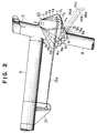
- a bicycle frame embodying the present invention includes a bracket lug 1, a seat lug 2, a head lug 3, a chain stay 7, a triangular link 10, a shock absorber cylinder assembly 11, and a rear fork member 14.
- the bracket lug 1, the seat lug 2 and the head lug 3 are linked by a seat tube 4, an upper tube 5 and a lower tube 6 to form a triangular structure.
- the chain stay 7 and the rear fork member to be described later are connected to the triangular structure to complete a bicycle frame.
- the chain stay 7 is pivotally connected at one end to the bracket lug 1 by means of a pin 9 and integrally connected at the other end to a rear axle support (rear fork end) 8.
- the rear axle support 8 is pivotally connected to the rear fork member 14 by means of a pin 8a.
- the triangular link 10 comprises a triangular plate member having a long side a , a medium side b and a short side c .
- the long side a and the short side c form therebetween a first apex d .
- a second apex e and a third apex f are respectively formed between the long side a and the medium side b and between the medium side b and the short side c .
- the triangular link 10 is pivotally connected at the first apex d to the seat lug 2 such that the long side a is directed to the shock absorber cylinder assembly 11, i.t., to the head lug 3.
- the shock absorber cylinder assembly 11 includes a hydraulic cylinder 11a which is pivotally connected at one end to the upper tube 5 by means of a mounting bracket 12 and a cylinder rod 13 which is urged outward to project from cylinder 11a.
- the outer end of the cylinder rod 13 is pivotally connected to the third apex f of the triangular link 10.
- a compression coil spring 11b is disposed around the cylinder 11a and the cylinder rod 13 and extends between the triangular link 10 and a flange on the cylinder 11a.
- the upper end of the rear fork member 14 is pivotally connected to the second apex e of the triangular link 10 so that the chain stay 7 swings counterclockwise as indicated by broken lines in Fig.
- the rear fork member 14 urges the second apex e of the triangular link 10 towards the shock absorber cylinder assembly 11 to rotate the triangular link 10 such that the second apex e of the triangular link 10 is moved from the position e through positions e1 and e2 to a position e3 towards the shock absorber cylinder assembly 11 around the supporting part (the first apex d ) of the seat lug 2, against the pressing force exerted to the triangular member 10 by the cylinder rod 13 and the spring 11b.
- the long side a moves as a1-a2-a3, the medium side b as b1-b2-b3, and the short side c as c1-c2-c3.
- the third apex f consequently moves progressively as f1-f2-f3, to thereby press the cylinder rod 13 along its longitudinal axis 13a. Therefore the shock absorber cylinder assembly 11 is progressively compressed.
- the present invention provides a bicycle frame comprising a bracket lug, a seat lug and a head lug linked by a seat tube, an upper tube and a lower tube to form a triangular frame structure, wherein a chain stay is provided rearwardly of the frame structure and pivotally connected at its one end to the bracket lug, a triangular link having a first apex formed between long and short sides, a second apex formed between the long side and a medium side and a third apex formed between the medium and short sides, the triangular link being pivotally connected at the first apex to the seat lug with the long side directed toward the head lug, a shock absorbing cylinder assembly has an end supported by the upper tube and includes a cylinder rod normally urged to project outward, the triangular link being pivotally connected at the third apex to a free end of the cylinder rod; and a rear fork member is provided between the second apex of the tri
- the chain stay swings about the supporting part of the bracket lug, allowing the rear axle support to be raised upward.
- the rear fork member urges the second apex of the triangular link towards the shock absorber cylinder assembly, so that the triangular link is rotated about the support part of the seat lug to causes the third apex to move towards the shock absorber cylinder assembly against the urging force exerted to the cylinder rod.
- the angle of rotation of the triangular link caused by the rear fork member is increased when the angle formed between the seat lug and a line interconnecting the first and second apices of the triangular link has been increased beyond 90°.
- the movement or displacement of the cylinder rod is therefore increased to produce an effect known as "progressive effect", to advantageously control upward displacement of the chain stay, whereby sufficient suspension and high rigidity are maintained to provide comfortable ride withoug power loss.
- the present invention is also capable of ensuring sufficient transverse rigidity for a bicycle frame which usually lacks transverse stability.
- a bicycle frame has a triangular frame structure formed by bracket, seat and head lugs (1, 2, 3) linked together by a seat tube (4), an upper tube (5) and a lower tube (6).
- a chain stay (7) is pivotally connected at a front end to the bracket lug (1) and has a rear end fixed to a rear axle support (8) to which a lower end of a rear fork member (14) is pivotally connected.
- a triangular link (10) is pivotally connected at a first point (d) adjacent a first apex thereof to the seat lug (2) and also pivotally connected at a second point (e) adjacent a second apex to the upper end of the rear fork member (14).
- the triangular link (10) is further pivotally connected at a third point (f) ajacent a third apex to a free end of a cylinder rod (13) of a shock absorbing assembly (11) having a cylinder (11a) pivotally connected to the upper tube (5) of the triangular frame structure, whereby the shock absorbing cylinder assembly (11) is operative not only to absorb a shock on the rearwheel but also to provide a "progressive effect" to enhance running performance and suspension and assure a frame rigidity.
Landscapes
- Engineering & Computer Science (AREA)
- Mechanical Engineering (AREA)
- Axle Suspensions And Sidecars For Cycles (AREA)
- Automatic Cycles, And Cycles In General (AREA)
Applications Claiming Priority (2)
| Application Number | Priority Date | Filing Date | Title |
|---|---|---|---|
| JP048295U JPH061175U (ja) | 1992-06-17 | 1992-06-17 | 自転車用フレーム |
| JP48295/92U | 1992-06-17 |
Publications (2)
| Publication Number | Publication Date |
|---|---|
| EP0574613A1 true EP0574613A1 (de) | 1993-12-22 |
| EP0574613B1 EP0574613B1 (de) | 1995-11-02 |
Family
ID=12799452
Family Applications (1)
| Application Number | Title | Priority Date | Filing Date |
|---|---|---|---|
| EP92120407A Expired - Lifetime EP0574613B1 (de) | 1992-06-17 | 1992-11-30 | Fahrradrahmen |
Country Status (6)
| Country | Link |
|---|---|
| US (1) | US5335929A (de) |
| EP (1) | EP0574613B1 (de) |
| JP (1) | JPH061175U (de) |
| AT (1) | ATE129677T1 (de) |
| CA (1) | CA2083636C (de) |
| DE (1) | DE69205825T2 (de) |
Cited By (7)
| Publication number | Priority date | Publication date | Assignee | Title |
|---|---|---|---|---|
| EP0769447A1 (de) * | 1995-10-19 | 1997-04-23 | Miyata Industry Co., Ltd. | Fahrradrahmen |
| WO1998003390A1 (de) * | 1996-07-22 | 1998-01-29 | Markus Storck | Fahrradrahmen |
| ES2116853A1 (es) * | 1994-09-12 | 1998-07-16 | Joseph Edward Kulhawik | Bicicleta que incorpora un bastidor bifurcado. |
| WO2001081159A1 (es) * | 2000-04-14 | 2001-11-01 | Rotor Componentes Tecnologicos, S.L. | Suspensión trasera progresiva para bicicletas con configuración de cuadrilátero de doble bucle deformable |
| EP1312543A3 (de) * | 2001-11-14 | 2005-05-25 | Canyon Bicycles GmbH | Fahrradrahmen |
| EP1698549A1 (de) * | 2005-03-02 | 2006-09-06 | Rocky Mountain Bicycles - a division of Groupe Procycle Inc. | Fahrrad mit Hinteraufhängung |
| WO2020201608A1 (es) * | 2019-04-04 | 2020-10-08 | Lizard Holding, S.L. | Sistema de suspensión trasera para vehículos |
Families Citing this family (57)
| Publication number | Priority date | Publication date | Assignee | Title |
|---|---|---|---|---|
| US5409249A (en) * | 1993-09-15 | 1995-04-25 | Gt Bicycles, Inc. | Bicycle rear suspension system |
| US5474318B1 (en) * | 1993-09-15 | 1997-12-30 | John P Castellano | Long-travel rear suspension system for bicycles |
| US5452910A (en) * | 1994-09-09 | 1995-09-26 | Rockshox, Inc. | Rear wheel suspension for a bicycle and bicycle equipped therewith |
| US5685553A (en) * | 1994-09-21 | 1997-11-11 | Trek Bicycle Corp. | Suspension for a bicycle having a Y shaped frame |
| US5671936A (en) * | 1995-08-10 | 1997-09-30 | Turner; David Roy | Shock absorbing bicycle frame apparatus |
| US6102421A (en) * | 1996-03-15 | 2000-08-15 | Schwinn Cycling & Fitness Inc. | Rear suspension for a bicycle |
| US5957473A (en) * | 1996-03-15 | 1999-09-28 | Schwinn Cycling & Fitness Inc. | Rear suspension bicycle |
| US5909890A (en) * | 1996-09-11 | 1999-06-08 | Sachs; Gregory D. | Device for locking and unlocking bicycle suspension systems |
| DE29618383U1 (de) | 1996-10-28 | 1998-01-08 | Kramer-Massow, Klaus, 79299 Wittnau | Hinterradzweiradfederung in der Ausführung eines Viergelenksystemes |
| AT406364B (de) * | 1997-04-24 | 2000-04-25 | Mlekusch Bernd Dipl Ing | Fahrradrahmen mit einem hauptrahmen und einer hinterradaufhängung |
| US6079726A (en) * | 1997-05-13 | 2000-06-27 | Gt Bicycles, Inc. | Direct drive bicycle |
| US6099010A (en) * | 1997-10-28 | 2000-08-08 | Gt Bicycles, Inc. | Bicycle with crank assembly suspension system |
| US6073950A (en) * | 1997-10-28 | 2000-06-13 | Busby; James S. | Bicycle with crank assembly suspension system |
| US6039137A (en) * | 1998-02-10 | 2000-03-21 | Schless; Ely | Multi-terrain electric motor driven cycle |
| US6164676A (en) * | 1998-02-20 | 2000-12-26 | Trek Bicycle Corporation | Variable reduction cross-linkage for rear suspension bicycle |
| US6203042B1 (en) | 1998-02-20 | 2001-03-20 | Trek Bicycle Corporation | Bicycle rear suspension system providing relative rearward motion of rear axle |
| US6378885B1 (en) | 1998-03-02 | 2002-04-30 | Anthony S. Ellsworth | Bicycle suspension apparatus and related method |
| US6076845A (en) * | 1998-09-24 | 2000-06-20 | Schwinn Cycling & Fitness Inc. | Rear suspension for a bicycle having a flexible chain stay |
| US6131934A (en) * | 1998-12-18 | 2000-10-17 | Sinclair; Christopher Jeffery | Bicycle rear suspension system |
| US6361059B1 (en) * | 1999-09-10 | 2002-03-26 | Anthony S. Ellsworth | Single pivot bicycle suspension apparatus and related methods |
| DE20205539U1 (de) | 2002-04-10 | 2002-07-25 | Derby Cycle Werke GmbH, 49661 Cloppenburg | Zweiradrahmen, insbesondere Fahrradrahmen |
| JP2004099013A (ja) * | 2002-07-19 | 2004-04-02 | Yamaha Motor Co Ltd | 鞍乗型車両における車体フレームの緩衝構造 |
| USD480336S1 (en) | 2002-08-27 | 2003-10-07 | Po-Chieh Yang | Frame of a tricycle for children |
| TWM241310U (en) * | 2003-08-18 | 2004-08-21 | Grand Bike Dev Ltd | Structure improvement on retractable bicycle |
| US7566066B2 (en) * | 2004-06-29 | 2009-07-28 | Giant Manufacturing Co., Ltd. | Bicycle rear suspension system |
| FR2872776B1 (fr) * | 2004-07-10 | 2008-08-08 | Cycles Lapierre Soc Par Action | Suspension arriere anti-pompage de vehicule a deux roues |
| US7722072B2 (en) | 2004-09-15 | 2010-05-25 | Yeti Cycling, Llc | Rear suspension system for a bicycle |
| US7066481B1 (en) | 2005-04-13 | 2006-06-27 | Felt Racing, Llc | Bicycle rear suspension |
| USD533811S1 (en) | 2006-01-03 | 2006-12-19 | Cycle Support West, Inc. | Woman's bicycle frame |
| USD533812S1 (en) | 2006-01-03 | 2006-12-19 | Cycle Support West | Men's bicycle frame |
| FR2912110B1 (fr) * | 2007-02-05 | 2009-04-24 | Promiles Snc | Vehicule a deux roues a suspension arriere |
| US7934739B2 (en) * | 2007-07-27 | 2011-05-03 | Niner, Inc. | Bicycle rear suspension |
| US8590914B2 (en) * | 2007-07-27 | 2013-11-26 | Niner, Inc. | Bicycle rear suspension |
| US20100109282A1 (en) * | 2008-09-16 | 2010-05-06 | David Weagle | Bicycle suspension systems |
| EP2605953B1 (de) | 2010-08-20 | 2021-06-16 | Yeti Cycling LLC | Bindeglied-aufhängungssystem |
| US9821879B2 (en) | 2010-08-20 | 2017-11-21 | Yeti Cycling, Llc | Reciprocating rail movement suspension system |
| US20120061941A1 (en) | 2010-09-13 | 2012-03-15 | Volagi, LLC | Bicycle frames and bicycles |
| USD637526S1 (en) | 2010-09-13 | 2011-05-10 | Volagi, LLC | Bicycle frame |
| US8857841B2 (en) | 2011-01-05 | 2014-10-14 | Trek Bicycle Corporation | Bicycle frame with passive seat tube pivot joint |
| US9216791B2 (en) * | 2011-03-14 | 2015-12-22 | Christopher Hudec | Bicycle suspension system |
| DE202011104974U1 (de) * | 2011-08-30 | 2012-12-03 | Canyon Bicycles Gmbh | Fahrradrahmen |
| US10766563B2 (en) | 2013-01-16 | 2020-09-08 | Yeti Cyclying, Llc | Rail suspension with integral shock and dampening mechanism |
| US10086899B2 (en) | 2015-05-17 | 2018-10-02 | Trek Bicycle Corporation | Adjustable compliance bicycle |
| EP3595963A4 (de) | 2017-03-17 | 2021-03-10 | Yeti Cycling, LLC | Fahrzeugaufhängungsgelenk |
| US12600431B2 (en) | 2017-03-17 | 2026-04-14 | Yeti Cycling, Llc | Vehicle suspension linkage |
| US10926830B2 (en) | 2017-07-07 | 2021-02-23 | Yeti Cycling, Llc | Vehicle suspension linkage |
| US12077241B2 (en) | 2019-02-01 | 2024-09-03 | Yeti Cycling, Llc | Multi-body vehicle suspension linkage |
| ES2784160A1 (es) * | 2019-03-21 | 2020-09-22 | Ingecid Investig Y Desarrollo De Proyectos S L | Cuadro para bicicleta con suspensión integrada. |
| US11440613B2 (en) * | 2019-05-29 | 2022-09-13 | Timothy Saul Lane | Bicycle suspension |
| US12145684B2 (en) | 2019-12-24 | 2024-11-19 | Yeti Cycling, Llc | Constrained multiple instantaneous velocity center linkage assembly for vehicle suspension |
| JP7614202B2 (ja) * | 2020-07-10 | 2025-01-15 | 株式会社 ビタミンアイファクトリー | 練習用自転車及び自転車フレーム |
| US12384484B2 (en) | 2020-11-18 | 2025-08-12 | Yeti Cycling, Llc | Integrated motor mount and suspension pivot |
| US12617488B2 (en) | 2021-09-09 | 2026-05-05 | Yeti Cycling, Llc | Two-wheeled vehicle with configurable idler |
| KR200496483Y1 (ko) * | 2022-06-27 | 2023-02-10 | 주식회사 부릉이 | 이륜차량의 완충구조 |
| JP2024039562A (ja) * | 2022-09-09 | 2024-03-22 | 株式会社 ビタミンアイファクトリー | 練習用自転車および自転車フレーム |
| US12565274B2 (en) | 2022-12-19 | 2026-03-03 | Toyota Motor Engineering & Manufacturing North America, Inc. | Bicycle seat with vibration isolation |
| US20240227969A1 (en) * | 2023-01-06 | 2024-07-11 | Toyota Motor Engineering & Manufacturing North America, Inc. | Bicycle frame with vibration isolation |
Citations (4)
| Publication number | Priority date | Publication date | Assignee | Title |
|---|---|---|---|---|
| GB104022A (en) * | 1916-02-18 | 1917-02-19 | Norman Tuckwood Downs | Improvements in Spring-frames for Motor Cycles and the like. |
| GB110272A (en) * | 1917-02-08 | 1917-10-18 | William Douglas | Improvements in or relating to Spring Frames for Cycles. |
| US3931990A (en) * | 1974-09-16 | 1976-01-13 | Yamaha International Corporation | Bicycle |
| AT374431B (de) * | 1981-06-10 | 1984-04-25 | Bombardier Rotax Gmbh | Vorrichtung zum federnden abstuetzen der hinterradschwinge eines zweirad-kraftfahrzeuges |
Family Cites Families (18)
| Publication number | Priority date | Publication date | Assignee | Title |
|---|---|---|---|---|
| US944795A (en) * | 1908-08-21 | 1909-12-28 | Edward H Leet | Frame for motor-cycles, bicycles, and the like. |
| FR923237A (fr) * | 1946-01-26 | 1947-07-01 | Machine automatique à fabriquer les boîtes en carton montées avec gorge | |
| JPS523498B2 (de) * | 1973-05-09 | 1977-01-28 | ||
| JPS5131437A (en) * | 1974-09-12 | 1976-03-17 | Yamaha Motor Co Ltd | Nirinsha |
| US3907332A (en) * | 1974-11-25 | 1975-09-23 | Donald G Richardson | Suspension system |
| JPS5237552A (en) * | 1975-09-22 | 1977-03-23 | Babcock Hitachi Kk | Dust separating packed tower |
| JPS5275738A (en) * | 1975-12-17 | 1977-06-25 | Hiroshi Tozawa | Rear wheel buffer for bicycle |
| FR2338470A1 (fr) * | 1976-01-15 | 1977-08-12 | Lab | Procede et installation pour le sechage et la transformation des matieres en suspension dans les liquides |
| JPS54156352A (en) * | 1978-05-31 | 1979-12-10 | Matsushita Electric Works Ltd | Purificatory apparatus for nightsoil |
| JPS5831749Y2 (ja) * | 1979-02-13 | 1983-07-14 | 本田技研工業株式会社 | 二輪車の後車輪懸架装置 |
| JPS55156776A (en) * | 1979-05-26 | 1980-12-06 | Honda Motor Co Ltd | Motorcycle |
| JPS57140285A (en) * | 1981-02-25 | 1982-08-30 | Yamaha Motor Co Ltd | Suspension system for rear wheel of autobicycle |
| JPS5812875A (ja) * | 1981-07-13 | 1983-01-25 | 本田技研工業株式会社 | 自動二輪車の後輪緩衝装置 |
| JPS6019031Y2 (ja) * | 1981-07-23 | 1985-06-08 | 本田技研工業株式会社 | 自動二輪車の後輪緩衝装置 |
| JPS58116287A (ja) * | 1981-12-29 | 1983-07-11 | ヤマハ発動機株式会社 | 自動二輪車のリヤサスペンシヨン |
| US4421337A (en) * | 1982-01-08 | 1983-12-20 | Pratt Thomas A | Bicycle with resiliently yieldable wheel supports |
| US4789174A (en) * | 1987-04-27 | 1988-12-06 | Mert Lawwill | Suspension bicycle |
| US5000470A (en) * | 1989-07-24 | 1991-03-19 | Kent International, Inc. | Bicycle having rear shock absorbing arrangement and improved shock absorber for bicycles |
-
1992
- 1992-06-17 JP JP048295U patent/JPH061175U/ja active Pending
- 1992-11-23 US US07/980,281 patent/US5335929A/en not_active Expired - Fee Related
- 1992-11-24 CA CA002083636A patent/CA2083636C/en not_active Expired - Fee Related
- 1992-11-30 DE DE69205825T patent/DE69205825T2/de not_active Expired - Fee Related
- 1992-11-30 AT AT92120407T patent/ATE129677T1/de active
- 1992-11-30 EP EP92120407A patent/EP0574613B1/de not_active Expired - Lifetime
Patent Citations (4)
| Publication number | Priority date | Publication date | Assignee | Title |
|---|---|---|---|---|
| GB104022A (en) * | 1916-02-18 | 1917-02-19 | Norman Tuckwood Downs | Improvements in Spring-frames for Motor Cycles and the like. |
| GB110272A (en) * | 1917-02-08 | 1917-10-18 | William Douglas | Improvements in or relating to Spring Frames for Cycles. |
| US3931990A (en) * | 1974-09-16 | 1976-01-13 | Yamaha International Corporation | Bicycle |
| AT374431B (de) * | 1981-06-10 | 1984-04-25 | Bombardier Rotax Gmbh | Vorrichtung zum federnden abstuetzen der hinterradschwinge eines zweirad-kraftfahrzeuges |
Cited By (10)
| Publication number | Priority date | Publication date | Assignee | Title |
|---|---|---|---|---|
| ES2116853A1 (es) * | 1994-09-12 | 1998-07-16 | Joseph Edward Kulhawik | Bicicleta que incorpora un bastidor bifurcado. |
| EP0769447A1 (de) * | 1995-10-19 | 1997-04-23 | Miyata Industry Co., Ltd. | Fahrradrahmen |
| WO1998003390A1 (de) * | 1996-07-22 | 1998-01-29 | Markus Storck | Fahrradrahmen |
| US6293574B1 (en) | 1996-07-22 | 2001-09-25 | Storck Bicycle Gmbh | Bicycle frame |
| WO2001081159A1 (es) * | 2000-04-14 | 2001-11-01 | Rotor Componentes Tecnologicos, S.L. | Suspensión trasera progresiva para bicicletas con configuración de cuadrilátero de doble bucle deformable |
| ES2164601A1 (es) * | 2000-04-14 | 2002-02-16 | Rotor Componentes Tecnologicos | Suspension trasera progresiva para bicicletas con configuracion de cuadrilatero de doble bucle defromable. |
| EP1312543A3 (de) * | 2001-11-14 | 2005-05-25 | Canyon Bicycles GmbH | Fahrradrahmen |
| EP1698549A1 (de) * | 2005-03-02 | 2006-09-06 | Rocky Mountain Bicycles - a division of Groupe Procycle Inc. | Fahrrad mit Hinteraufhängung |
| US7216883B2 (en) | 2005-03-02 | 2007-05-15 | Rocky Mountain Bicycles-A Division Of Procycle Group Inc. | Bicycle with rear suspension |
| WO2020201608A1 (es) * | 2019-04-04 | 2020-10-08 | Lizard Holding, S.L. | Sistema de suspensión trasera para vehículos |
Also Published As
| Publication number | Publication date |
|---|---|
| EP0574613B1 (de) | 1995-11-02 |
| ATE129677T1 (de) | 1995-11-15 |
| DE69205825D1 (de) | 1995-12-07 |
| DE69205825T2 (de) | 1996-04-18 |
| CA2083636A1 (en) | 1993-12-18 |
| US5335929A (en) | 1994-08-09 |
| JPH061175U (ja) | 1994-01-11 |
| CA2083636C (en) | 1996-02-20 |
Similar Documents
| Publication | Publication Date | Title |
|---|---|---|
| US5335929A (en) | Bicycle frame | |
| US5599034A (en) | Single arm bicycle suspension fork | |
| CA2424428C (en) | Rear suspension system for two-wheeled vehicles, particularly bicycles | |
| US4789174A (en) | Suspension bicycle | |
| EP1481884B1 (de) | Hinteraufhängung für Fahrräder | |
| EP1572524B1 (de) | Aufhängungssysteme | |
| US5121937A (en) | Suspension bicycle | |
| US6336647B1 (en) | Front wheel suspension in a two-wheeled vehicle | |
| US6357775B1 (en) | Bottom link type front wheel suspension for motorcycle | |
| US20040061305A1 (en) | Rear wheel suspension system for a bicycle | |
| JP4138975B2 (ja) | 二輪車の前輪懸架装置 | |
| US20110193316A1 (en) | Bicycle rear suspension system | |
| EP1698549A1 (de) | Fahrrad mit Hinteraufhängung | |
| WO1999010224A1 (en) | Rear suspension for a bicycle | |
| CA2343368A1 (en) | Anti-dive front suspension | |
| US8602428B2 (en) | Methods of vehicle suspension | |
| WO1996007582A1 (en) | Rear wheel suspension for a bicycle and bicycle equipped therewith | |
| US20020038944A1 (en) | Rear suspension for a bicycle | |
| JPH09109974A (ja) | 自転車用フレーム | |
| JPH09109973A (ja) | 自転車用フレーム | |
| GB2331966A (en) | A front wheel bicycle suspension with a pivoted rocking arm | |
| JPH0649507Y2 (ja) | フロントフオ−ク | |
| JPS61178281A (ja) | 自動三輪車の後輪緩衝装置 | |
| JPS6015744Y2 (ja) | 二輪車の前車輪懸架装置 | |
| JPS602072Y2 (ja) | 二輪車の後車輪懸架装置 |
Legal Events
| Date | Code | Title | Description |
|---|---|---|---|
| PUAI | Public reference made under article 153(3) epc to a published international application that has entered the european phase |
Free format text: ORIGINAL CODE: 0009012 |
|
| AK | Designated contracting states |
Kind code of ref document: A1 Designated state(s): AT BE CH DE DK ES FR GB IT LI LU NL SE |
|
| 17P | Request for examination filed |
Effective date: 19940211 |
|
| 17Q | First examination report despatched |
Effective date: 19941216 |
|
| GRAA | (expected) grant |
Free format text: ORIGINAL CODE: 0009210 |
|
| AK | Designated contracting states |
Kind code of ref document: B1 Designated state(s): AT BE CH DE DK ES FR GB IT LI LU NL SE |
|
| PG25 | Lapsed in a contracting state [announced via postgrant information from national office to epo] |
Ref country code: ES Free format text: THE PATENT HAS BEEN ANNULLED BY A DECISION OF A NATIONAL AUTHORITY Effective date: 19951102 Ref country code: DK Effective date: 19951102 Ref country code: AT Effective date: 19951102 Ref country code: BE Effective date: 19951102 |
|
| REF | Corresponds to: |
Ref document number: 129677 Country of ref document: AT Date of ref document: 19951115 Kind code of ref document: T |
|
| ITF | It: translation for a ep patent filed | ||
| PG25 | Lapsed in a contracting state [announced via postgrant information from national office to epo] |
Ref country code: LU Free format text: LAPSE BECAUSE OF NON-PAYMENT OF DUE FEES Effective date: 19951130 |
|
| PGFP | Annual fee paid to national office [announced via postgrant information from national office to epo] |
Ref country code: CH Payment date: 19951130 Year of fee payment: 4 |
|
| REF | Corresponds to: |
Ref document number: 69205825 Country of ref document: DE Date of ref document: 19951207 |
|
| ET | Fr: translation filed | ||
| PG25 | Lapsed in a contracting state [announced via postgrant information from national office to epo] |
Ref country code: SE Effective date: 19960202 |
|
| REG | Reference to a national code |
Ref country code: CH Ref legal event code: PL |
|
| PLBE | No opposition filed within time limit |
Free format text: ORIGINAL CODE: 0009261 |
|
| STAA | Information on the status of an ep patent application or granted ep patent |
Free format text: STATUS: NO OPPOSITION FILED WITHIN TIME LIMIT |
|
| 26N | No opposition filed | ||
| PGFP | Annual fee paid to national office [announced via postgrant information from national office to epo] |
Ref country code: FR Payment date: 19961129 Year of fee payment: 5 Ref country code: GB Payment date: 19961129 Year of fee payment: 5 Ref country code: NL Payment date: 19961129 Year of fee payment: 5 |
|
| PG25 | Lapsed in a contracting state [announced via postgrant information from national office to epo] |
Ref country code: CH Free format text: LAPSE BECAUSE OF FAILURE TO SUBMIT A TRANSLATION OF THE DESCRIPTION OR TO PAY THE FEE WITHIN THE PRESCRIBED TIME-LIMIT Effective date: 19961130 Ref country code: LI Free format text: LAPSE BECAUSE OF FAILURE TO SUBMIT A TRANSLATION OF THE DESCRIPTION OR TO PAY THE FEE WITHIN THE PRESCRIBED TIME-LIMIT Effective date: 19961130 |
|
| PGFP | Annual fee paid to national office [announced via postgrant information from national office to epo] |
Ref country code: DE Payment date: 19961231 Year of fee payment: 5 |
|
| PG25 | Lapsed in a contracting state [announced via postgrant information from national office to epo] |
Ref country code: FR Free format text: THE PATENT HAS BEEN ANNULLED BY A DECISION OF A NATIONAL AUTHORITY Effective date: 19971130 Ref country code: GB Free format text: LAPSE BECAUSE OF NON-PAYMENT OF DUE FEES Effective date: 19971130 |
|
| PG25 | Lapsed in a contracting state [announced via postgrant information from national office to epo] |
Ref country code: NL Free format text: LAPSE BECAUSE OF NON-PAYMENT OF DUE FEES Effective date: 19980601 |
|
| GBPC | Gb: european patent ceased through non-payment of renewal fee |
Effective date: 19971130 |
|
| PG25 | Lapsed in a contracting state [announced via postgrant information from national office to epo] |
Ref country code: DE Free format text: LAPSE BECAUSE OF NON-PAYMENT OF DUE FEES Effective date: 19980801 |
|
| NLV4 | Nl: lapsed or anulled due to non-payment of the annual fee |
Effective date: 19980601 |
|
| REG | Reference to a national code |
Ref country code: FR Ref legal event code: ST |
|
| PG25 | Lapsed in a contracting state [announced via postgrant information from national office to epo] |
Ref country code: IT Free format text: LAPSE BECAUSE OF NON-PAYMENT OF DUE FEES;WARNING: LAPSES OF ITALIAN PATENTS WITH EFFECTIVE DATE BEFORE 2007 MAY HAVE OCCURRED AT ANY TIME BEFORE 2007. THE CORRECT EFFECTIVE DATE MAY BE DIFFERENT FROM THE ONE RECORDED. Effective date: 20051130 |