EP0574825B1 - Procédé et dispositif pour fixer des ferrures à des cadres de fenêtre - Google Patents
Procédé et dispositif pour fixer des ferrures à des cadres de fenêtre Download PDFInfo
- Publication number
- EP0574825B1 EP0574825B1 EP93109308A EP93109308A EP0574825B1 EP 0574825 B1 EP0574825 B1 EP 0574825B1 EP 93109308 A EP93109308 A EP 93109308A EP 93109308 A EP93109308 A EP 93109308A EP 0574825 B1 EP0574825 B1 EP 0574825B1
- Authority
- EP
- European Patent Office
- Prior art keywords
- frame
- boring
- screwing
- axis
- leaf
- Prior art date
- Legal status (The legal status is an assumption and is not a legal conclusion. Google has not performed a legal analysis and makes no representation as to the accuracy of the status listed.)
- Expired - Lifetime
Links
- 238000000034 method Methods 0.000 title claims description 13
- 238000006073 displacement reaction Methods 0.000 claims description 5
- 239000004429 Calibre Substances 0.000 claims 1
- 230000000903 blocking effect Effects 0.000 claims 1
- 238000005553 drilling Methods 0.000 description 31
- 238000004519 manufacturing process Methods 0.000 description 8
- 238000003754 machining Methods 0.000 description 3
- 230000008878 coupling Effects 0.000 description 2
- 238000010168 coupling process Methods 0.000 description 2
- 238000005859 coupling reaction Methods 0.000 description 2
- 229910052751 metal Inorganic materials 0.000 description 2
- 239000002184 metal Substances 0.000 description 2
- 125000006850 spacer group Chemical group 0.000 description 2
- 229910052782 aluminium Inorganic materials 0.000 description 1
- XAGFODPZIPBFFR-UHFFFAOYSA-N aluminium Chemical compound [Al] XAGFODPZIPBFFR-UHFFFAOYSA-N 0.000 description 1
- 230000003287 optical effect Effects 0.000 description 1
- 230000007704 transition Effects 0.000 description 1
Images

Classifications
-
- E—FIXED CONSTRUCTIONS
- E04—BUILDING
- E04F—FINISHING WORK ON BUILDINGS, e.g. STAIRS, FLOORS
- E04F21/00—Implements for finishing work on buildings
-
- B—PERFORMING OPERATIONS; TRANSPORTING
- B23—MACHINE TOOLS; METAL-WORKING NOT OTHERWISE PROVIDED FOR
- B23Q—DETAILS, COMPONENTS, OR ACCESSORIES FOR MACHINE TOOLS, e.g. ARRANGEMENTS FOR COPYING OR CONTROLLING; MACHINE TOOLS IN GENERAL CHARACTERISED BY THE CONSTRUCTION OF PARTICULAR DETAILS OR COMPONENTS; COMBINATIONS OR ASSOCIATIONS OF METAL-WORKING MACHINES, NOT DIRECTED TO A PARTICULAR RESULT
- B23Q3/00—Devices holding, supporting, or positioning work or tools, of a kind normally removable from the machine
- B23Q3/18—Devices holding, supporting, or positioning work or tools, of a kind normally removable from the machine for positioning only
- B23Q3/183—Centering devices
-
- B—PERFORMING OPERATIONS; TRANSPORTING
- B27—WORKING OR PRESERVING WOOD OR SIMILAR MATERIAL; NAILING OR STAPLING MACHINES IN GENERAL
- B27F—DOVETAILED WORK; TENONS; SLOTTING MACHINES FOR WOOD OR SIMILAR MATERIAL; NAILING OR STAPLING MACHINES
- B27F5/00—Slotted or mortised work
- B27F5/02—Slotting or mortising machines tools therefor
- B27F5/12—Slotting or mortising machines tools therefor for making holes designed for taking up fittings, e.g. in frames of doors, windows, furniture
-
- B—PERFORMING OPERATIONS; TRANSPORTING
- B27—WORKING OR PRESERVING WOOD OR SIMILAR MATERIAL; NAILING OR STAPLING MACHINES IN GENERAL
- B27M—WORKING OF WOOD NOT PROVIDED FOR IN SUBCLASSES B27B - B27L; MANUFACTURE OF SPECIFIC WOODEN ARTICLES
- B27M3/00—Manufacture or reconditioning of specific semi-finished or finished articles
- B27M3/0006—Devices for fixing fittings into holes
-
- B—PERFORMING OPERATIONS; TRANSPORTING
- B23—MACHINE TOOLS; METAL-WORKING NOT OTHERWISE PROVIDED FOR
- B23P—METAL-WORKING NOT OTHERWISE PROVIDED FOR; COMBINED OPERATIONS; UNIVERSAL MACHINE TOOLS
- B23P2700/00—Indexing scheme relating to the articles being treated, e.g. manufactured, repaired, assembled, connected or other operations covered in the subgroups
- B23P2700/08—Fittings for doors and windows of buildings
Definitions
- the invention relates to a method for fastening corresponding band parts to window frames and window sashes, in which fastening elements for the band parts are attached to the window frame and window sash at certain positions.
- the hinge parts of window frames and sashes are generally attached to assembly devices in window manufacturing.
- Known mounting devices work according to a method in which the scanner scans the outer or inner dimensions of the frame or sash and the position of the fastening elements is spatially assigned to these scanners. This assignment is preferably achieved by a rigid coupling between the scanners and the devices for attaching the fastening elements.
- the positions of the fasteners relative to the inner or outer dimension of the frame or wing are determined so that the distances between the hinge parts on the wing to the distances between the hinge parts on the frame by the allowable tolerance of the inner or outer dimension on the sash and frame can vary. The result of these spacing variations is that only one of several bands takes up the main load.
- the object of the invention is to provide a method in which the band parts of a window are fastened to the frame and the sash in such a way that all the bands of the window carry essentially the same part load. Another object is to fasten the band parts to the frame and to the sash in such a way that the sash is articulated centrally to the opening in the frame which receives it.
- the object is achieved in that the distances of all positions of the fastening elements on the frame and on the wing are determined relative to the center of the frame and wing, the positions of the fastening elements on the frame relative to the center of its internal height dimension and on the wing relative to the center of it outer height dimension can be determined.
- the manufacturing tolerances of the frame and sash dimensions do not affect the spacing of the hinge parts from one another.
- the positions of the holes for the fasteners can be determined, for example, with a rigid spacer that is centered on the frame or sash.
- window frames and sashes are symmetrical and have the same profiles made at close tolerances at the top, bottom and sides. With components of this type, it is immaterial whether the component center is determined on the basis of the internal dimension or the external dimension.
- the outer height dimension that is, the sash rebate height
- the inner height dimension that is the distance between the frame legs, which lie opposite the upper and lower sash rebate when the window is closed.
- the frame or sash To use the method in automated window production, the frame or sash must be placed on an assembly device and centered on it so that the center of the frame or wing coincides with the center of the mounting device.
- the positions of the fastening elements of the band parts can then be determined using a distance gauge which is permanently installed on the mounting device and has the position markings relative to the center of the mounting device.
- the device for centering and fixing the frame or sash consists of two counter-rotating clamping blocks, which are coupled to one another, for example, by means of a connecting band and deflection rollers.
- the clamping blocks can be driven pneumatically or mechanically, and the coupling of the clamping blocks can also take place via a gear, for example racks arranged on the clamping blocks, which run parallel to one another and are coupled to one another via a gearwheel.
- the spacer gauge permanently installed on the mounting device can be formed, for example, by pin receptacles arranged on the front of the mounting table, into which a locking pin engages, which is arranged on the slide which carries the devices for attaching the fastening elements.
- a pin receptacle must be provided for each machining position.
- the pin receptacles can be formed by a metal strip, which has locking grooves on the front at intervals of e.g. 25 mm to each other.
- the hinge parts can thus be attached to the optimal positions on the frame profile or sash profile.
- a drill and a screw-in device in particular for attaching tapes in which the wing hinge part is screwed into the wing profile with a central screw-in pin and the screw holes for fastening the frame hinge part are symmetrical to the center of the hinge part, a drill and a screw-in device, the axes of which are on the carriage lie essentially in the plane of the assembly table, and a drilling template is arranged which has vertically extending drill bushings.
- the axes of the drilling and screwing devices as well as the center line of the drilling template lie in the same plane perpendicular to the table plane.
- the arrangement of the three processing devices on a slide is inexpensive, and the machining of the wing profiles, in which a hole is first made and then the screw-in pin of the wing hinge part is screwed in, is not very time-consuming, since it is not necessary to position a second slide with the screw-in device, but only the rack carrying the equipment has to be moved from the working position of the drill to the working position of the screwdriver in height.
- the slide To make the frame hinge holes, the slide must be brought into the same locking positions as for the wing hinge part, because due to the central screw-in pin, no offset between the screw-in pin axis and the center line of the drilling pattern is required for the frame hinge attachment.
- the pull-out drilling template can then be placed on the frame profile and the holes can be made through the drill bushings in the frame profile. Because the drilling pattern of the frame hinge part is symmetrical to the middle of the band, it does not matter whether the band is to be arranged on the right or left of the window. This arrangement of the three fastening devices one above the other can also be used advantageously regardless of the fastening method claimed.
- drilling template is a cost-effective solution and is advantageous, for example, in the transition from manual production to partially automated production.
- a drilling device can be used instead of the template, which has several drills arranged at a distance from the screw holes of the frame hinge part with a drilling axis and feed direction running at right angles to the table plane.
- Another alternative to the device with superimposed drill and screwdriver axes is a device in which these axes lie side by side in a horizontal plane.
- a device is used, for example, if an aluminum support profile is used as the guide rail for the slide, so that this support profile forms a separate structural unit with the slide and tools.
- the working positions are horizontally next to each other in the direction of the guide rail.
- a control device is to be provided which only releases the drive of the corresponding tool in the respective working position. This can be done by means of an end stop button which emits a signal when the support frame bears against a stop for the working position of the drill.
- the air supply for a pneumatic drill is activated with a three-way valve and that of the screwdriver is blocked. If the signal is not present, then is the air supply for the screws is switched on and that for the drill blocked.
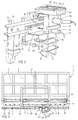
- the table surface is open and consists of longitudinal struts 2 and cross struts 3.
- the front section of the table surface has no cross struts.
- a slide rail 4 is arranged, on which two centering slides 5, 6 are guided, on the top of which the clamping blocks 7, 8 are fastened.
- the centering slide 5 can be automatically pushed back and forth via a pneumatic drive in the slide rail 4.
- the centering slide 6 is connected to the centering slide 5 via a circumferential connecting band 9, for example a fiber-reinforced toothed belt or a thin metal band, and is therefore necessarily at the same distance from the center of the slide rail 4 and thus from the center of the assembly table 1.
- the connecting band 9 becomes at the ends of the Guide rail 4 deflected via deflection rollers 10.
- 1 swiveling stop rollers 11 are arranged in the front region of the assembly table.
- the stop rollers 11 pivot about an axis perpendicular to the slide rail 4 and parallel to the table plane, so that the window frame or sash can be moved without resistance in the direction of the slide rail 4 on the assembly table.
- a rod-shaped guide rail 13 is arranged, on which the carriage 14 is guided, which carries the processing equipment.
- the front side 12 of the assembly table 1 has pin receptacles 15, into which a resilient locking pin 16, which is fastened to the slide 14 and engages by hand, engages.
- the pin receptacles 15 can also be replaced by a bar (not shown) running parallel to the guide rail 13 with locking grooves for the engagement of the locking pin 16.
- the support frame 17 On the carriage 14, the support frame 17 is arranged, on which the processing devices are attached. With the guide rods 18 running at right angles to the table plane, the carrying frame 17 is fastened to the carriage so as to be displaceable in the vertical direction. The vertical displacement takes place through the two pneumatic cylinders 19. The vertical displacement takes place only in two discrete positions, namely the working positions of the processing devices. Since the sash and frame are to be machined with different profile widths, a device (not shown here) is to be provided for adjusting the horizontal distance of the vertical locking positions relative to the table plane.
- the shift in the machining direction takes place via the two essentially horizontal guide rods 20.
- the guiding and shifting device for the slide 14 and the carrying frame 17 are indicated schematically in all representations and are not shown in all details.
- the drilling device 21 with the drill 22 is attached to the support frame 17.
- the screwing device 24 for screwing in the screw-in pins of the wing hinge part is arranged above the drilling device 21.
- the wing hinge part can be inserted into the hinge part receptacle 25 of the screwing device 24.
- the axis of rotation of the drill 22 and the screw-in axis of the tape part receptacle 25 run parallel to one another and are located in the same vertical plane running at right angles to the front 12 of the table.
- the support frame 17 therefore only has to be moved downward in the vertical direction in order to screw the wing hinge part in order to bring the screwing device 24 into its working position.
- a feed sensor 27 is arranged in addition to the tape part receptacle 25 of the screwing device 24.
- the control device interrupts the air supply to the pneumatic screwing device 24 and thus ends the screwing movement.
- a feed sensor 27 cooperates with one of the horizontal guide rods 20 and gives a signal to the control device when the support frame 17 is off rear end position is shifted in the feed direction. Due to this signal, the control device blocks the vertical raising or lowering of the support frame 17, so that the drill 22, the band part receptacle 25 or the wing profile cannot be damaged by the fact that the support frame 17 is displaced vertically while one of the tools 22, 25 with the Sash profile is engaged.
- FIG. 1 also shows the air lines 31 for the air supply to the pneumatic screwing device 24, the pneumatic drilling device 17 and for the pneumatic drive in the slide rail 4.
- FIG. 2 shows an enlarged illustration of the slide 14 fastened to the assembly table 1 with the frame 17 carrying the tools.
- a drilling template 41 with drill bushes 42 is arranged above the screwing device 24.
- the center line 40 of the drilling template 41 runs parallel to and in the same vertical plane with the drilling axis 23 of the drill 22 and the screwing axis 26 of the hinge part receptacle 25.
- This arrangement enables the holes for the frame hinge parts of hinge, in which the screw pin of the wing hinge part in the band center is arranged, since here no offset between the hinge pin bore made with the drill 22 and the center of the drilling pattern of the drilling template is necessary. If the screw-in pin of the wing hinge part is not in the center, the drilling template must be shiftable to the right and left by the offset of the screw-in pin, depending on whether the tapes are to be arranged on the right or left of the window.
- the drilling template can be displaced in the direction of its center line and is guided in a U-shaped template carrier 43 with as little play as possible in the other directions. To do this the guide pin 45 of the drilling template 41 into a respective guide slot 44 in the side walls of the template carrier 43. Only a section of the front frame support with the stop rollers 11 is shown in FIG. 2 of the assembly table 1.
- FIG. 3 shows the assembly table 1 with a frame profile 46 clamped in the center, on which the drilling template 41 is placed.
- the holes for fastening the frame band part can now be made through the drill bushings 42 of the drilling template 41 in the frame profile 46.
- the centering and locking mechanism for the window frame or sash can be clearly seen again.
- the connecting band 9 is clamped with the clamping parts 48 screwed to the centering slide 5, 6.
- the deflection of the connecting band 9 at the table ends takes place with the deflecting rollers 10.
- the clamping blocks 7, 8 arranged on the centering slides 5, 6 interact with the inner surfaces of the frame profile 46 and thus tighten the frame in the middle on the assembly table 1.
- the stop for the frame profile 46 is in the direction of the table center line 47 forming stop rollers 11.
- the frame profile 46 can be pressed against the stop rollers 11 by a pneumatic pressure bolt (not shown here) arranged on the slide 14.
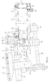
- FIG. 4 shows a schematic side view of the processing devices 21, 24, 41 on the support frame 17 with a section through the assembly table 1 and through the frame profile 46.
- the drilling template 41 is placed on its end face.
- the bore axis 50 of the drill bushings 42 runs at right angles to the table plane 52.
- sliding brushes 51 are arranged on the longitudinal struts 2 and cross struts 3 of the assembly table 1, one of which is shown schematically in FIG. 4. So that it is possible to move the frame profile in the longitudinal direction of the table in spite of the stop rollers 11 projecting from the table plane 52, the stop rollers 11 are articulated on the assembly table so as to be pivotable about the axis 53.
- the essentially horizontal guide rods 20 of the support frame 17 are guided in two axial bearings 54 fastened to the slide 14 for guidance in the feed direction of the drilling device 21 and of the screwing device 24.
- the feed direction is not completely parallel to the table plane 52, but is inclined 5 ° to it, since greater forces can be transmitted from the screw-in pin to the wing profile by a slight inclination of the screw-in pin of the wing hinge part.
- the carriage 14 is guided through the axial bearing 57 on the guide rail 13.
- a second guide by means of the ball bearings 55 on a roller track 56, which runs parallel to the front 12 of the table, prevents the slide 14 from tilting about the axis of the round guide rail 13.
- the locking pin 16 can no longer be operated manually, but is moved back and forth with a pneumatic cylinder 59.
Landscapes
- Engineering & Computer Science (AREA)
- Life Sciences & Earth Sciences (AREA)
- Architecture (AREA)
- Wood Science & Technology (AREA)
- Forests & Forestry (AREA)
- Mechanical Engineering (AREA)
- Manufacturing & Machinery (AREA)
- Civil Engineering (AREA)
- Structural Engineering (AREA)
- Drilling And Boring (AREA)
- Tape Measures (AREA)
- Automatic Assembly (AREA)
Claims (14)
- Procédé pour fixer des éléments de penture adaptés l'un à l'autre sur des dormants de fenêtre et des ouvrants de fenêtre, dans lequel des éléments de fixation des pentures sont montés sur le dormant de fenêtre et sur l'ouvrant de fenêtre en des positions déterminées,
caractérisé en ce que les différents espacements entre les positions des éléments de fixation sur le dormant et sur l'ouvrant sont définis par rapport au milieu du dormant et de l'ouvrant, la position des éléments de fixation étant déterminée par rapport au milieu de sa hauteur intérieure pour le dormant et par rapport au milieu de sa hauteur extérieure pour l'ouvrant. - Procédé selon la revendication 1, caractérisé en ce que le dormant ou l'ouvrant est posé sur un dispositif de montage (1) et centré sur celui-ci, de telle sorte que le milieu du dormant ou de l'ouvrant coïncide avec le milieu (47) du dispositif de montage (1) et en ce que les positions des éléments de fixation sont définies au moyen d'une règle d'espacement qui équipe de façon fixe le dispositif de montage (1).
- Dispositif pour fixer les éléments de penture sur des dormants de fenêtre et des ouvrants de fenêtre selon le procédé de la revendication 2, constitué par une table de montage (1) comportant un dispositif (4 à 10) pour centrer et immobiliser le dormant ou l'ouvrant, un rail de guidage (13) disposé dans le sens longitudinal de la table de montage (1) et un chariot (14) disposé de façon à pouvoir coulisser sur celui-ci et sur lequel est montée au moins une perceuse (21) dont l'axe de perçage (23) est disposé perpendiculairement au rail de guidage (13), la perceuse (21) pouvant se déplacer dans la direction de l'axe de perçage (23),
caractérisé en ce que la table de montage (1) comporte des dispositifs de butée (15) placés selon des espacements déterminés par rapport à son milieu et en ce que le chariot (14) est doté d'éléments de blocage (16) coopérant avec ces dispositifs de butée (15). - Dispositif, en particulier selon la revendication 3, caractérisé en ce que l'axe de perçage (23) se déplace essentiellement parallèlement au plan de la table (52) et en ce que sur le chariot (14) est également prévue une visseuse (24) dont l'axe de vissage (26) est coplanaire avec l'axe de perçage (23) et parallèle à celui-ci, la perceuse (24) et la visseuse (21) étant fixées au chariot (14) par l'intermédiaire d'un support (17) pouvant se déplacer entre deux positions de travail, perpendiculairement à l'axe de perçage (23) et à l'axe de vissage (26) dans le plan défini par ces deux axes, et se déplacer en translation de façon continue dans la direction des axes de perçage et de vissage.
- Dispositif selon la revendication 4, caractérisé en ce qu'il comprend un dispositif de commande doté d'un détecteur d'avance (27) qui envoie un signal au dispositif de commande lorsque le support (17) est déplacé vers la table de travail (1) dans la direction de l'axe de vissage (26) ou de l'axe de perçage (23), le dispositif de commande, en fonction de ce signal, verrouillant le déplacement du support (17) dans l'autre direction.
- Dispositif selon l'une ou l'autre des revendications 4 et 5, caractérisé en ce qu'il comporte un moyen d'entraînement, par exemple un vérin pneumatique à double effet, grâce auquel le support (17) peut être positionné contre des butées de fin de course correspondant aux deux positions de travail.
- Dispositif selon l'une quelconque des revendications 4 à 6, caractérisé en ce qu'il comporte un dispositif de commande doté d'un détecteur de position qui envoie un signal au dispositif de commande lorsque le support (17) se trouve dans l'une ou l'autre des positions de travail, le dispositif de commande n'autorisant, en présence de ce signal, que l'entraînement de l'outil (21 ou 24) correspondant à cette position de travail et, en l'absence de ce signal, que l'entraînement de l'autre outil (24 ou 21).
- Dispositif selon l'une quelconque des revendications 4 à 7, caractérisé en ce qu'un dispositif est prévu sur le support (17) pour régler l'espacement entre les deux positions de travail et le plan de travail (52).
- Dispositif selon l'une quelconque des revendications 4 à 8, caractérisé en ce qu'il comporte un dispositif de commande doté d'un détecteur de contact (28) qui, en touchant le montant de l'ouvrant, envoie un signal au dispositif de commande lorsque la visseuse (24), lors du vissage d'un élément de penture dans le montant de l'ouvrant, arrive en fin de course de vissage, le dispositif de commande arrêtant le mouvement de vissage de la visseuse (24) dès réception de ce signal.
- Dispositif selon l'une quelconque des revendications 3 à 9, caractérisé en ce que sur le chariot (14) est prévu un dispositif pour effectuer les perçages selon des directions de perçage (50) perpendiculaires au plan de la table (52).
- Dispositif selon la revendication 10, en particulier pour effectuer des perçages de dormant pour des éléments de penture de telle sorte que les trous de vis de la penture de dormant soient symétriques par rapport au milieu de la penture, caractérisé en ce que le dispositif pour effectuer des perçages dans le dormant est un gabarit de perçage (41) pouvant être posé sur le chant du montant de dormant (46) en coopérant avec une perceuse portative et qui comporte des doùilles de perçage (42) perpendiculaires au plan de la table (52), et qui peut être avancé ou reculé essentiellement parallèlement au plan de la table (52) et perpendiculairement au rail de guidage (13) en s'articulant sur le support (17), le gabarit de perçage (41) comportant une butée (49) se posant sur le montant de dormant (46).
- Dispositif selon la revendication 11 pour effectuer des perçages de dormant pour des éléments de penture avec goujons filetés médians sur la penture côté ouvrant, caractérisé en ce que l'axe central (40) du tracé de perçage du gabarit de perçage (41) se trouve dans le plan vertical de l'axe de perçage (23) et/ou de l'axe de vissage (26).
- Dispositif selon la revendication 11 pour effectuer des perçages de dormant pour des éléments de penture avec un déport entre le goujon fileté de la penture d'ouvrant et le milieu de l'élément de penture, caractérisé en ce que le gabarit de perçage (41) peut être fixé de façon réglable sur le support (17) selon deux positions dans lesquelles l'axe central (40) du gabarit de perçage (41) est décalé parallèlement au rail de guidage (13) dans chaque direction d'une distance égale à la valeur du déport par rapport à l'axe de perçage (23) et/ou de l'axe de vissage (26).
- Dispositif selon la revendication 10, caractérisé en ce que le dispositif pour effectuer des perçages dans le dormant est une perceuse montée sur le chariot (14) de façon à pouvoir se déplacer perpendiculairement au plan de la table (52).
Applications Claiming Priority (4)
| Application Number | Priority Date | Filing Date | Title |
|---|---|---|---|
| DE4218697 | 1992-06-09 | ||
| DE4218697 | 1992-06-09 | ||
| DE4234496A DE4234496A1 (de) | 1992-06-09 | 1992-10-14 | Verfahren und Vorrichtung für das Befestigen der Bandteile an Fensterrahmen und -flügeln |
| DE4234496 | 1992-10-14 |
Publications (2)
| Publication Number | Publication Date |
|---|---|
| EP0574825A1 EP0574825A1 (fr) | 1993-12-22 |
| EP0574825B1 true EP0574825B1 (fr) | 1997-01-08 |
Family
ID=25915469
Family Applications (1)
| Application Number | Title | Priority Date | Filing Date |
|---|---|---|---|
| EP93109308A Expired - Lifetime EP0574825B1 (fr) | 1992-06-09 | 1993-06-09 | Procédé et dispositif pour fixer des ferrures à des cadres de fenêtre |
Country Status (3)
| Country | Link |
|---|---|
| EP (1) | EP0574825B1 (fr) |
| DE (2) | DE4234496A1 (fr) |
| ES (1) | ES2097393T3 (fr) |
Cited By (1)
| Publication number | Priority date | Publication date | Assignee | Title |
|---|---|---|---|---|
| CN105459242A (zh) * | 2015-12-15 | 2016-04-06 | 嵊州市古艺木雕装饰有限公司 | 一种木板装饰块安装装置 |
Families Citing this family (5)
| Publication number | Priority date | Publication date | Assignee | Title |
|---|---|---|---|---|
| DE29510197U1 (de) † | 1995-06-23 | 1996-10-31 | Dr. Hahn GmbH & Co. KG, 41189 Mönchengladbach | Stangenbohrlehre |
| DE19712082C2 (de) * | 1997-03-22 | 2001-08-23 | Lemuth Praez Steile Gmbh | Vorrichtung zur automatischen Montage von Beschlagteilen an den Flügeln eines Fensters oder dergleichen |
| CN113172385A (zh) * | 2021-05-10 | 2021-07-27 | 安徽蓝柏教育科技有限公司 | 一种机器人焊接管道自动化推进装置 |
| CN113857516B (zh) * | 2021-08-23 | 2022-10-04 | 湖南亘晟门窗幕墙有限公司 | 一种外框内扇组装一体自动生产线 |
| CN115609691B (zh) * | 2022-10-27 | 2023-12-05 | 湖北千川门窗有限公司 | 一种精确度高的木门加工用钻孔装置及其钻孔方法 |
Family Cites Families (6)
| Publication number | Priority date | Publication date | Assignee | Title |
|---|---|---|---|---|
| DE6602838U (de) * | 1965-08-09 | 1969-07-10 | Erwin Jenkner | Bearbeitungsmaschine für rahmenf¦rmigewerkstuecke |
| DE2149966B2 (de) * | 1971-10-07 | 1975-12-18 | Uniquick Gietzelt Kg, 4831 Marienfeld | Vorrichtung zum montieren von tuerschloessern in tueren |
| DE2152565A1 (de) * | 1971-10-21 | 1973-04-26 | Alfred Locher | Bohr- und einsetzautomat |
| FR2188474A5 (fr) * | 1972-06-01 | 1974-01-18 | Gache Henri | |
| DE2421666C3 (de) * | 1974-05-04 | 1978-09-14 | Jakob 5401 Mermuth Kneip | Vorrichtung zum Bohren der Einlaßlöcher für Beschläge von Fenstern |
| DE3437092A1 (de) * | 1984-10-10 | 1986-04-10 | Hartmut 6540 Simmern Federhenn | Montagevorrichtung fuer fenster, tueren und dergleichen |
-
1992
- 1992-10-14 DE DE4234496A patent/DE4234496A1/de not_active Withdrawn
-
1993
- 1993-06-09 ES ES93109308T patent/ES2097393T3/es not_active Expired - Lifetime
- 1993-06-09 EP EP93109308A patent/EP0574825B1/fr not_active Expired - Lifetime
- 1993-06-09 DE DE59305023T patent/DE59305023D1/de not_active Expired - Fee Related
Cited By (1)
| Publication number | Priority date | Publication date | Assignee | Title |
|---|---|---|---|---|
| CN105459242A (zh) * | 2015-12-15 | 2016-04-06 | 嵊州市古艺木雕装饰有限公司 | 一种木板装饰块安装装置 |
Also Published As
| Publication number | Publication date |
|---|---|
| DE4234496A1 (de) | 1993-12-16 |
| ES2097393T3 (es) | 1997-04-01 |
| EP0574825A1 (fr) | 1993-12-22 |
| DE59305023D1 (de) | 1997-02-20 |
Similar Documents
| Publication | Publication Date | Title |
|---|---|---|
| DE50209459C5 (de) | Maschine und Verfahren zum Bearbeiten von Werkstücken aus Holz, Kunststoff oder dergleichen | |
| DE3390141C2 (de) | Vorrichtung zur Endbearbeitung eines in ein zylindrisches Stück geschnittenen Schraubenganges durch Glattwalzen | |
| DE3338943C2 (fr) | ||
| EP0574825B1 (fr) | Procédé et dispositif pour fixer des ferrures à des cadres de fenêtre | |
| DE3533404A1 (de) | Holzbearbeitungsmaschine | |
| DE3900304C2 (fr) | ||
| EP2913465B1 (fr) | Dispositif de charniere pour portes, fenetres ou similaires | |
| EP0292864B1 (fr) | Machine pour travailler le bois | |
| DE8631175U1 (de) | Vorrichtung zum Bearbeiten von Kanten von plattenförmigen Werkstücken | |
| DE69003267T2 (de) | Werkzeuganordnung zum Ausschneiden von Scharniersitzen. | |
| DE3817005A1 (de) | Schweissmaschine zur herstellung von rahmen | |
| WO2024061874A1 (fr) | Ferrure à translation-rotation et élément de mobilier ou d'appareil électroménager | |
| EP0212484B2 (fr) | Ferme-porte | |
| EP0536532A2 (fr) | Machine à percer, notamment pour le travail du bois | |
| EP1437196B1 (fr) | Dispositif pour l'usinage des profilés creux le long plusieurs faces | |
| EP0445363A1 (fr) | Dispositif de fraisage ou perçage | |
| EP0649503B1 (fr) | Palier d'appui pour unites en mouvement a guidage lineaire | |
| DE3508756A1 (de) | Vorrichtung zum bohren von loechern an den innenflaechen von abstandhalterrahmen fuer isolierglasscheiben | |
| DE19805574B4 (de) | Verfahren und Vorrichtung zum Transport und zur Vorbereitung von hohlen Profilstäben aus Kunststoff für die Bildung von Fensterrahmen | |
| EP0160217A1 (fr) | Agrégat de fraisage | |
| DE29703693U1 (de) | Bohrständer | |
| DE102008060911A1 (de) | Vorrichtung zum Ausrichten von Werkstücken | |
| DE202022003162U1 (de) | Translations-Rotations-Beschlag und Möbel- oder Haushaltsgeräteelement | |
| EP2604781A2 (fr) | Dispositif de serrage | |
| DE19546859A1 (de) | Vorrichtung zum paßgenauen Bohren |
Legal Events
| Date | Code | Title | Description |
|---|---|---|---|
| PUAI | Public reference made under article 153(3) epc to a published international application that has entered the european phase |
Free format text: ORIGINAL CODE: 0009012 |
|
| AK | Designated contracting states |
Kind code of ref document: A1 Designated state(s): AT BE CH DE DK ES FR GB GR IE IT LI LU MC NL PT SE |
|
| RBV | Designated contracting states (corrected) |
Designated state(s): DE ES FR IT |
|
| 17P | Request for examination filed |
Effective date: 19940621 |
|
| RAP1 | Party data changed (applicant data changed or rights of an application transferred) |
Owner name: SCHUERING GMBH & CO. FENSTERTECHNOLOGIE KG |
|
| GRAG | Despatch of communication of intention to grant |
Free format text: ORIGINAL CODE: EPIDOS AGRA |
|
| GRAH | Despatch of communication of intention to grant a patent |
Free format text: ORIGINAL CODE: EPIDOS IGRA |
|
| 17Q | First examination report despatched |
Effective date: 19960513 |
|
| GRAH | Despatch of communication of intention to grant a patent |
Free format text: ORIGINAL CODE: EPIDOS IGRA |
|
| GRAA | (expected) grant |
Free format text: ORIGINAL CODE: 0009210 |
|
| AK | Designated contracting states |
Kind code of ref document: B1 Designated state(s): DE ES FR IT |
|
| REF | Corresponds to: |
Ref document number: 59305023 Country of ref document: DE Date of ref document: 19970220 |
|
| ITF | It: translation for a ep patent filed | ||
| REG | Reference to a national code |
Ref country code: ES Ref legal event code: FG2A Ref document number: 2097393 Country of ref document: ES Kind code of ref document: T3 |
|
| ET | Fr: translation filed | ||
| PLBE | No opposition filed within time limit |
Free format text: ORIGINAL CODE: 0009261 |
|
| STAA | Information on the status of an ep patent application or granted ep patent |
Free format text: STATUS: NO OPPOSITION FILED WITHIN TIME LIMIT |
|
| 26N | No opposition filed | ||
| PG25 | Lapsed in a contracting state [announced via postgrant information from national office to epo] |
Ref country code: DE Free format text: LAPSE BECAUSE OF NON-PAYMENT OF DUE FEES Effective date: 19980303 |
|
| PGFP | Annual fee paid to national office [announced via postgrant information from national office to epo] |
Ref country code: ES Payment date: 20010709 Year of fee payment: 9 |
|
| PG25 | Lapsed in a contracting state [announced via postgrant information from national office to epo] |
Ref country code: ES Free format text: LAPSE BECAUSE OF NON-PAYMENT OF DUE FEES Effective date: 20020610 |
|
| REG | Reference to a national code |
Ref country code: ES Ref legal event code: FD2A Effective date: 20030711 |
|
| PG25 | Lapsed in a contracting state [announced via postgrant information from national office to epo] |
Ref country code: IT Free format text: LAPSE BECAUSE OF NON-PAYMENT OF DUE FEES Effective date: 20050609 |
|
| PGFP | Annual fee paid to national office [announced via postgrant information from national office to epo] |
Ref country code: FR Payment date: 20110630 Year of fee payment: 19 |
|
| REG | Reference to a national code |
Ref country code: FR Ref legal event code: ST Effective date: 20130228 |
|
| PG25 | Lapsed in a contracting state [announced via postgrant information from national office to epo] |
Ref country code: FR Free format text: LAPSE BECAUSE OF NON-PAYMENT OF DUE FEES Effective date: 20120702 |