EP0574840A2 - Appareil pour mesurer le débordement d'un bout de fibre optique dans un connecteur - Google Patents
Appareil pour mesurer le débordement d'un bout de fibre optique dans un connecteur Download PDFInfo
- Publication number
- EP0574840A2 EP0574840A2 EP93109351A EP93109351A EP0574840A2 EP 0574840 A2 EP0574840 A2 EP 0574840A2 EP 93109351 A EP93109351 A EP 93109351A EP 93109351 A EP93109351 A EP 93109351A EP 0574840 A2 EP0574840 A2 EP 0574840A2
- Authority
- EP
- European Patent Office
- Prior art keywords
- optical fiber
- connector
- ferrule
- fixed
- movable measuring
- Prior art date
- Legal status (The legal status is an assumption and is not a legal conclusion. Google has not performed a legal analysis and makes no representation as to the accuracy of the status listed.)
- Granted
Links
Images

Classifications
-
- G—PHYSICS
- G01—MEASURING; TESTING
- G01B—MEASURING LENGTH, THICKNESS OR SIMILAR LINEAR DIMENSIONS; MEASURING ANGLES; MEASURING AREAS; MEASURING IRREGULARITIES OF SURFACES OR CONTOURS
- G01B7/00—Measuring arrangements characterised by the use of electric or magnetic techniques
- G01B7/14—Measuring arrangements characterised by the use of electric or magnetic techniques for measuring distance or clearance between spaced objects or spaced apertures
Definitions
- This invention generally relates to the art of electrical or communications connectors and, particularly, to an apparatus for measuring the distance an optical fiber terminated in a connector protrudes from a component of the connector, such as a connector ferrule or the like.
- the distal ends of the fibers terminated in a pair of mating connectors usually are maintained in physical contact with each other.
- the ends of the fibers conventionally are flat, polished and in abutment with each other to minimize transmission losses between the fibers.
- the fiber ends protrude slightly from components of the mating connectors, such as ceramic ferrules which embrace the fibers.
- One of the problems in fiber optic connectors of the character described is to maintain a particular protruding length of the fibers beyond the connector components or ferrules. If the protruding end of a fiber is too long, the fiber can break due to high stresses created in the mated connectors. If the fiber protrusion is too short, physical contact between the fiber ends can be difficult, resulting in a decrease in performance/transmission quality, i.e. an increase in transmission losses. For instance, it has been found that fiber protrusion in a given fiber optic connector may be as small as in the 0.1 to 2.5 micron range, in order to establish a good physical contact between the abutting ends of the optical fibers.
- An object, therefore, of the invention is to provide a novel apparatus for measuring the distance and optical fiber protrudes from a component of a fiber optic connector within which the optical fiber is terminated.
- the measuring apparatus includes a fixed abutment member against which the connector component can be moved into engagement.
- a movable measuring member is mounted for movement relative to the fixed abutment member and is engageable by a distal end of the optical fiber as the connector component is moved into engagement with the fixed abutment member. Therefore, the amount of relative movement between the movable measuring member and the fixed abutment member directly corresponds to the distance the optical fiber protrudes from the connector component.
- Calculating means are provided, operatively associated with at least the movable measuring member of the apparatus, for calculating its amount of movement and, thereby, the protruding distance of the optical fiber.
- the fixed abutment member of the apparatus is provided in the form of a ferrule-like member shaped complementarily to the connector component or ferrule.
- An alignment sleeve surrounds the fixed abutment member and projects from an end thereof for guiding the connector component into abutment therewith.
- the movable measuring member is provided in the form of a needle-like member telescoped within a passageway through the fixed abutment member, with a distal end of the needle-like member engageable by the distal end of the optical fiber.
- the passageway is configured such that the distal end of the optical fiber is movable thereinto as the fiber moves the needle-like member.
- the invention contemplates that the calculating means include means for sensing relative movement between the movable measuring member and the fixed abutment member, means coupled to the sensing means for generating an electrical signal, and means responsive to the electrical signal for determining the protruding distance of the optical fiber.
- the means for sensing relative movement between the movable measuring member and the fixed abutment member are provided as capacitor means including one capacitor plate coupled to the movable measuring member and another capacitor plate fixed to the fixed abutment member.
- an apparatus for measuring the distance an optical fiber 12, terminated in a connector, protrudes from a component 14 of the connector.
- component 14 often is a ceramic or metal ferrule having a generally planar end 14a beyond which a protruding distal end 12a of the optical fiber protrudes.
- the protruding distal end of the optical fiber is intended to engage or make physical contact with the distal end of another optical fiber of a mating connector, all of which is known in the art.
- Fiber end 12a often protrudes from ferrule 14 a small distance on the order of 0.1 to 2.5 microns.
- Apparatus 10 is designed to measure the protruding distance of fiber end 12a to insure that the distance the fiber end protrudes from planar end 14a of connector component 14 is in the acceptable range.
- apparatus 10 includes a fixed abutment member 16 and a movable measuring member which includes a holder 18 and a needle 20 fixed to the holder whereby the needle can move with the holder in the direction of double-headed arrow "A" relative to fixed abutment member 16.
- Needle 20 extends through a passageway 22 in a ferrule-like portion 24 of fixed abutment member 16.
- Ferrule-like portion 24 is shaped complementarily to connector component or ferrule 14, and an alignment sleeve 26 surrounds the ferrule-like portion and the connector component so that, upon insertion of the connector component into the sleeve in the direction of arrow "B", fiber end 12a will be in alignment with needle 20 and passageway 22.
- a position sensing means 28 is provided for sensing movement of holder 18 and needle 20 relative to fixed abutment member 16 and its depending ferrule-like portion 24.
- Various forms of position sensing means can be employed, a specific capacitor sensing system being shown in Figures 3 and 4 which will be described in greater detail hereinafter.
- Figure 2 shows an enlarged depiction of connector component or ferrule 14 and the ferrule-like portion 24 of fixed abutment member 16 in alignment within alignment sleeve 26. It can be seen that protruding end 12a of optical fiber 12 is in alignment with and, in fact, is shown already projecting into passageway 22, with needle 20 being reciprocal within the passageway in the direction of double-headed arrow "C".
- apparatus 10 The simplicity of operation of apparatus 10 is one of its major attributes.
- a user simply inserts connector component 14 into the bottom of alignment sleeve 26 in the direction of arrow "B".
- Needle 20 extends downwardly through passage 22 at least to the bottom surface 24a so that initial engagement is between fiber end 12a and the end of the needle. Further movement of the connector component causes the needle and its holder 18 to move upwardly relative to fixed abutment member 16 and its ferrule-like portion 24, until connector component 14 abuts against the ferrule-like portion. Further movement of the connector component is stopped, and the relative movement between fixed abutment member 16 and holder 18 of the movable measuring member can be measured by using an appropriate position sensing device.
- a variety of position sensing devices could be used, such as capacitive sensors, variable reluctance sensors, sensors of the fiber optic reflective type, or the like.
- a capacitive sensing scheme will be described below, in relation to Figures 3 and 4.
- the amount of movement of needle 20 and holder 18 of the movable measuring member does not have to be precisely equal to the distance fiber end 12a protrudes from connector component 14, because measurements can be made based on a particular position of movable measuring member 18 and needle 20.
- abutment interface 30 between connector component 14 and ferrule-like portion 24 of movable measuring member 16 defines a reference surface for measurement.
- the distance which fiber end 12a projects beyond planar surface 14a of connector component 14 defines the position of needle 20 relative to abutment interface 30.
- this protruding distance also is defined by the position of holder 18 of the movable measuring member (which is fixed to the movable needle) and fixed abutment member 16 (which is fixed to ferrule-like portion 24).
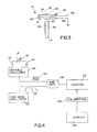
- Figure 3 shows connector component 14 moved into alignment sleeve 26 into abutment with ferrule-like portion 24 depending from fixed abutment member 16.
- the fixed abutment member is fabricated in the form of a magnetic steel disc.
- Movable measuring member 18 is a laminated structure fabricated of an aluminum disk 32 sandwiched between a magnet washer 34 and a dielectric film 36. Needle 20 is fixed by an appropriate fastening means 38 to the laminated movable measuring member 18.
- Fixed abutment member 16 and movable measuring member 18 in essence, form capacitor plates connected by electrical contacts or leads 40 and 42, respectively, to a variable oscillator, as will be described below in relation to Figure 4.
- variable oscillator circuit 44 The variable oscillator circuit generates a pulse train signal, shown at 46, having a frequency varying as a function of the capacitance of the capacitor plates 16 and 18.
- the oscillator circuit 44 is connected to an input of an AND gate 48.
- Another input of the AND gate 48 is connected to a time base oscillator circuit 50.
- the time base oscillator circuit 50 generates a fixed frequency signal, shown at 52, at a frequency significantly lower than the variable oscillator 44.
- the AND gate 48 outputs the variable frequency signal 46 during the time base determined by the fixed frequency signal 52.
- This provides a fixed time base during which pulses in the variable frequency pulse train 46 are counted by a counter 53 to provide a total count.
- This total count which is proportional to the frequency of the pulse train, represents capacitance.
- the count total from the counter 53 is then converted into microns or any other appropriate unit by interpolation on a calibration curve by a calibrating device 54, the result being displayed on a display device 56. It should be understood that a microprocessor could be used to perform most of these functions.
- the measuring apparatus can also be used to measure small negative protrusions of the fiber end 12a, i.e. recess of the fiber end below the planar end 14a of the ferrule due to over polishing.
Landscapes
- Physics & Mathematics (AREA)
- General Physics & Mathematics (AREA)
- Length Measuring Devices With Unspecified Measuring Means (AREA)
- Mechanical Coupling Of Light Guides (AREA)
- Manufacturing Of Electrical Connectors (AREA)
Applications Claiming Priority (2)
| Application Number | Priority Date | Filing Date | Title |
|---|---|---|---|
| US07/898,657 US5224275A (en) | 1992-06-15 | 1992-06-15 | Apparatus for measuring the protrusion of an end of an optical fiber terminated in a connector |
| US898657 | 1997-07-22 |
Publications (3)
| Publication Number | Publication Date |
|---|---|
| EP0574840A2 true EP0574840A2 (fr) | 1993-12-22 |
| EP0574840A3 EP0574840A3 (en) | 1994-09-07 |
| EP0574840B1 EP0574840B1 (fr) | 1998-02-18 |
Family
ID=25409828
Family Applications (1)
| Application Number | Title | Priority Date | Filing Date |
|---|---|---|---|
| EP93109351A Expired - Lifetime EP0574840B1 (fr) | 1992-06-15 | 1993-06-11 | Appareil pour mesurer le débordement d'un bout de fibre optique dans un connecteur |
Country Status (4)
| Country | Link |
|---|---|
| US (1) | US5224275A (fr) |
| EP (1) | EP0574840B1 (fr) |
| JP (1) | JP2522752B2 (fr) |
| DE (1) | DE69317013T2 (fr) |
Cited By (1)
| Publication number | Priority date | Publication date | Assignee | Title |
|---|---|---|---|---|
| CN103968748A (zh) * | 2014-05-29 | 2014-08-06 | 龚永祥 | 线缆金属包覆带搭接宽度自动监测装置及监测方法 |
Families Citing this family (3)
| Publication number | Priority date | Publication date | Assignee | Title |
|---|---|---|---|---|
| US5465497A (en) * | 1994-02-22 | 1995-11-14 | General Electric Company | Control rod drive uncoupling tool gage |
| US5566464A (en) * | 1994-05-20 | 1996-10-22 | Emerson Electric Co. | Electric motor shaft extension gage |
| US20070232987A1 (en) * | 2006-02-22 | 2007-10-04 | Vicente Diaz | One-hand-operated ultrasound transducer and method for delivering a controlled and uniform distribution of a sterile or a non-sterile topical reagent to skin for use in diagnostic, therapeutic, and aesthetic therapies |
Family Cites Families (16)
| Publication number | Priority date | Publication date | Assignee | Title |
|---|---|---|---|---|
| US2560571A (en) * | 1947-11-03 | 1951-07-17 | Aline B Hawkins | Gauge |
| GB919413A (en) * | 1959-05-11 | 1963-02-27 | Mullard Ltd | Improvements in and relating to gauges |
| GB1059167A (en) * | 1962-10-18 | 1967-02-15 | Sogenique Service Ltd | Improvements in and relating to metrological apparatus |
| US3413726A (en) * | 1966-09-16 | 1968-12-03 | Champion Spark Plug Co | Gauging device |
| US3848339A (en) * | 1973-02-09 | 1974-11-19 | R Strasbaugh | Cylometer |
| DE2439580C3 (de) * | 1974-08-17 | 1982-09-23 | Achenbach Buschhütten GmbH, 5910 Kreuztal | Meßeinrichtung zur Ermittlung des Abstandes der Stützwalzeneinbaustücke eines Quarto-Walzgerüstes |
| JPS60169606U (ja) * | 1984-04-19 | 1985-11-11 | 日立電線株式会社 | 光フアイバコネクタのフエル−ル插入装置 |
| CH664100A5 (en) * | 1984-05-04 | 1988-02-15 | Guenther Alich | Roller-gap measuring system - uses calibration spindle and servo control with sensors for roller movement |
| CH664825A5 (de) * | 1984-09-17 | 1988-03-31 | Agf Max Gasser | Vorrichtung zur pruefung der einstellung des pfeilfuehrungsknopfes an einem sportbogen. |
| JPS6194804U (fr) * | 1984-11-26 | 1986-06-18 | ||
| SU1428907A1 (ru) * | 1985-04-24 | 1988-10-07 | Институт Прикладной Физики Ан Бсср | Способ поверки электромагнитных толщиномеров покрытий |
| JPH0532803Y2 (fr) * | 1985-04-26 | 1993-08-23 | ||
| JPH0648312B2 (ja) * | 1987-06-16 | 1994-06-22 | 三菱原子燃料株式会社 | 位置決め装置 |
| US4993167A (en) * | 1989-04-03 | 1991-02-19 | Susan M. Durfee | Dressing tool gauge for positioning cutting tools in removable head type dressers |
| US4930226A (en) * | 1989-05-22 | 1990-06-05 | Deere & Company | Sensor adjustment gauge |
| US5077909A (en) * | 1991-02-06 | 1992-01-07 | Patten Industries, Inc. | Method and apparatus for measuring valve stem wear |
-
1992
- 1992-06-15 US US07/898,657 patent/US5224275A/en not_active Expired - Fee Related
-
1993
- 1993-05-11 JP JP5132870A patent/JP2522752B2/ja not_active Expired - Lifetime
- 1993-06-11 DE DE69317013T patent/DE69317013T2/de not_active Expired - Fee Related
- 1993-06-11 EP EP93109351A patent/EP0574840B1/fr not_active Expired - Lifetime
Cited By (2)
| Publication number | Priority date | Publication date | Assignee | Title |
|---|---|---|---|---|
| CN103968748A (zh) * | 2014-05-29 | 2014-08-06 | 龚永祥 | 线缆金属包覆带搭接宽度自动监测装置及监测方法 |
| CN103968748B (zh) * | 2014-05-29 | 2016-09-07 | 日照阳光电力设计有限公司 | 线缆金属包覆带搭接宽度自动监测装置及监测方法 |
Also Published As
| Publication number | Publication date |
|---|---|
| DE69317013D1 (de) | 1998-03-26 |
| US5224275A (en) | 1993-07-06 |
| JP2522752B2 (ja) | 1996-08-07 |
| DE69317013T2 (de) | 1998-10-01 |
| EP0574840A3 (en) | 1994-09-07 |
| JPH0651164A (ja) | 1994-02-25 |
| EP0574840B1 (fr) | 1998-02-18 |
Similar Documents
| Publication | Publication Date | Title |
|---|---|---|
| JP3335205B2 (ja) | 光学システムの較正方法 | |
| US4574625A (en) | Surface finish, displacement and contour scanner | |
| US5119024A (en) | Optical device for sensing magnetic inductions | |
| EP0926479A1 (fr) | Messurer des pertes optiques | |
| US5224275A (en) | Apparatus for measuring the protrusion of an end of an optical fiber terminated in a connector | |
| EP0866313A1 (fr) | Un capteur et une méthode pour la mesure de distances à une matière et/ou ses propriétés physiques | |
| JPS6166936A (ja) | 物理パラメータ測定用の光・電気・機械的装置 | |
| JPH10115644A (ja) | 光集積化電圧センサ | |
| CN221325364U (zh) | 一种平整度测量组件 | |
| US5010770A (en) | Vibrating tube fiber optic pressure transducer with light-powered electro-magnetic drive | |
| FR3141252B1 (fr) | Dispositif de détection d'un champ magnétique et système de mesure d'un champ magnétique comprenant un tel dispositif | |
| CN110631745B (zh) | 压力传感元件及压力传感系统 | |
| CN112378312B (zh) | 齿轮托架张开量测量装置 | |
| CN220568296U (zh) | 压力传感器、测量装置和具有测量装置的装置 | |
| JPH0317569A (ja) | 電線ケーブルの断線故障点検出装置 | |
| CN111366751A (zh) | 基于硅波导耦合特性的悬臂梁加速度检测计及系统 | |
| JPH09505881A (ja) | 所定位置較正のためのドリフト補正手段を有する光ファイバ圧力センサ | |
| JP3058428B2 (ja) | レンズメータ | |
| CN212432485U (zh) | 一种测试纤插回损测试工装 | |
| CN211060800U (zh) | 一种检测机构 | |
| Seguin et al. | Interferometric pressure-sensing system using ion-exchanged glass waveguides | |
| KR200266920Y1 (ko) | 다기능 높이 측정기 | |
| JPH06160197A (ja) | パルス試験器およびこれを用いた光損失測定方法 | |
| KR100262309B1 (ko) | 광화이버 고정 툴 키트 | |
| SU1167506A1 (ru) | Способ измерени механических величин |
Legal Events
| Date | Code | Title | Description |
|---|---|---|---|
| PUAI | Public reference made under article 153(3) epc to a published international application that has entered the european phase |
Free format text: ORIGINAL CODE: 0009012 |
|
| AK | Designated contracting states |
Kind code of ref document: A2 Designated state(s): DE FR GB IT |
|
| PUAL | Search report despatched |
Free format text: ORIGINAL CODE: 0009013 |
|
| AK | Designated contracting states |
Kind code of ref document: A3 Designated state(s): DE FR GB IT |
|
| 17P | Request for examination filed |
Effective date: 19950127 |
|
| 17Q | First examination report despatched |
Effective date: 19960522 |
|
| GRAG | Despatch of communication of intention to grant |
Free format text: ORIGINAL CODE: EPIDOS AGRA |
|
| GRAG | Despatch of communication of intention to grant |
Free format text: ORIGINAL CODE: EPIDOS AGRA |
|
| GRAH | Despatch of communication of intention to grant a patent |
Free format text: ORIGINAL CODE: EPIDOS IGRA |
|
| ITF | It: translation for a ep patent filed | ||
| GRAH | Despatch of communication of intention to grant a patent |
Free format text: ORIGINAL CODE: EPIDOS IGRA |
|
| GRAA | (expected) grant |
Free format text: ORIGINAL CODE: 0009210 |
|
| AK | Designated contracting states |
Kind code of ref document: B1 Designated state(s): DE FR GB IT |
|
| REF | Corresponds to: |
Ref document number: 69317013 Country of ref document: DE Date of ref document: 19980326 |
|
| ET | Fr: translation filed | ||
| PLBE | No opposition filed within time limit |
Free format text: ORIGINAL CODE: 0009261 |
|
| STAA | Information on the status of an ep patent application or granted ep patent |
Free format text: STATUS: NO OPPOSITION FILED WITHIN TIME LIMIT |
|
| 26N | No opposition filed | ||
| PGFP | Annual fee paid to national office [announced via postgrant information from national office to epo] |
Ref country code: GB Payment date: 20010502 Year of fee payment: 9 |
|
| PGFP | Annual fee paid to national office [announced via postgrant information from national office to epo] |
Ref country code: FR Payment date: 20010531 Year of fee payment: 9 |
|
| PGFP | Annual fee paid to national office [announced via postgrant information from national office to epo] |
Ref country code: DE Payment date: 20010627 Year of fee payment: 9 |
|
| REG | Reference to a national code |
Ref country code: GB Ref legal event code: IF02 |
|
| PG25 | Lapsed in a contracting state [announced via postgrant information from national office to epo] |
Ref country code: GB Free format text: LAPSE BECAUSE OF NON-PAYMENT OF DUE FEES Effective date: 20020611 |
|
| PG25 | Lapsed in a contracting state [announced via postgrant information from national office to epo] |
Ref country code: DE Free format text: LAPSE BECAUSE OF NON-PAYMENT OF DUE FEES Effective date: 20030101 |
|
| GBPC | Gb: european patent ceased through non-payment of renewal fee |
Effective date: 20020611 |
|
| PG25 | Lapsed in a contracting state [announced via postgrant information from national office to epo] |
Ref country code: FR Free format text: LAPSE BECAUSE OF NON-PAYMENT OF DUE FEES Effective date: 20030228 |
|
| REG | Reference to a national code |
Ref country code: FR Ref legal event code: ST |
|
| PG25 | Lapsed in a contracting state [announced via postgrant information from national office to epo] |
Ref country code: IT Free format text: LAPSE BECAUSE OF NON-PAYMENT OF DUE FEES;WARNING: LAPSES OF ITALIAN PATENTS WITH EFFECTIVE DATE BEFORE 2007 MAY HAVE OCCURRED AT ANY TIME BEFORE 2007. THE CORRECT EFFECTIVE DATE MAY BE DIFFERENT FROM THE ONE RECORDED. Effective date: 20050611 |