EP0575105B1 - Démarreur - Google Patents
Démarreur Download PDFInfo
- Publication number
- EP0575105B1 EP0575105B1 EP93304532A EP93304532A EP0575105B1 EP 0575105 B1 EP0575105 B1 EP 0575105B1 EP 93304532 A EP93304532 A EP 93304532A EP 93304532 A EP93304532 A EP 93304532A EP 0575105 B1 EP0575105 B1 EP 0575105B1
- Authority
- EP
- European Patent Office
- Prior art keywords
- pinion gear
- support shaft
- spring
- shift
- push rod
- Prior art date
- Legal status (The legal status is an assumption and is not a legal conclusion. Google has not performed a legal analysis and makes no representation as to the accuracy of the status listed.)
- Expired - Lifetime
Links
Images
Classifications
-
- F—MECHANICAL ENGINEERING; LIGHTING; HEATING; WEAPONS; BLASTING
- F02—COMBUSTION ENGINES; HOT-GAS OR COMBUSTION-PRODUCT ENGINE PLANTS
- F02N—STARTING OF COMBUSTION ENGINES; STARTING AIDS FOR SUCH ENGINES, NOT OTHERWISE PROVIDED FOR
- F02N15/00—Other power-operated starting apparatus; Component parts, details, or accessories, not provided for in, or of interest apart from groups F02N5/00 - F02N13/00
- F02N15/02—Gearing between starting-engines and started engines; Engagement or disengagement thereof
- F02N15/04—Gearing between starting-engines and started engines; Engagement or disengagement thereof the gearing including disengaging toothed gears
- F02N15/06—Gearing between starting-engines and started engines; Engagement or disengagement thereof the gearing including disengaging toothed gears the toothed gears being moved by axial displacement
-
- F—MECHANICAL ENGINEERING; LIGHTING; HEATING; WEAPONS; BLASTING
- F02—COMBUSTION ENGINES; HOT-GAS OR COMBUSTION-PRODUCT ENGINE PLANTS
- F02N—STARTING OF COMBUSTION ENGINES; STARTING AIDS FOR SUCH ENGINES, NOT OTHERWISE PROVIDED FOR
- F02N11/00—Starting of engines by means of electric motors
-
- F—MECHANICAL ENGINEERING; LIGHTING; HEATING; WEAPONS; BLASTING
- F02—COMBUSTION ENGINES; HOT-GAS OR COMBUSTION-PRODUCT ENGINE PLANTS
- F02N—STARTING OF COMBUSTION ENGINES; STARTING AIDS FOR SUCH ENGINES, NOT OTHERWISE PROVIDED FOR
- F02N15/00—Other power-operated starting apparatus; Component parts, details, or accessories, not provided for in, or of interest apart from groups F02N5/00 - F02N13/00
- F02N15/02—Gearing between starting-engines and started engines; Engagement or disengagement thereof
- F02N15/04—Gearing between starting-engines and started engines; Engagement or disengagement thereof the gearing including disengaging toothed gears
- F02N15/06—Gearing between starting-engines and started engines; Engagement or disengagement thereof the gearing including disengaging toothed gears the toothed gears being moved by axial displacement
- F02N15/067—Gearing between starting-engines and started engines; Engagement or disengagement thereof the gearing including disengaging toothed gears the toothed gears being moved by axial displacement the starter comprising an electro-magnetically actuated lever
-
- Y—GENERAL TAGGING OF NEW TECHNOLOGICAL DEVELOPMENTS; GENERAL TAGGING OF CROSS-SECTIONAL TECHNOLOGIES SPANNING OVER SEVERAL SECTIONS OF THE IPC; TECHNICAL SUBJECTS COVERED BY FORMER USPC CROSS-REFERENCE ART COLLECTIONS [XRACs] AND DIGESTS
- Y10—TECHNICAL SUBJECTS COVERED BY FORMER USPC
- Y10T—TECHNICAL SUBJECTS COVERED BY FORMER US CLASSIFICATION
- Y10T74/00—Machine element or mechanism
- Y10T74/13—Machine starters
- Y10T74/131—Automatic
- Y10T74/132—Separate power mesher
-
- Y—GENERAL TAGGING OF NEW TECHNOLOGICAL DEVELOPMENTS; GENERAL TAGGING OF CROSS-SECTIONAL TECHNOLOGIES SPANNING OVER SEVERAL SECTIONS OF THE IPC; TECHNICAL SUBJECTS COVERED BY FORMER USPC CROSS-REFERENCE ART COLLECTIONS [XRACs] AND DIGESTS
- Y10—TECHNICAL SUBJECTS COVERED BY FORMER USPC
- Y10T—TECHNICAL SUBJECTS COVERED BY FORMER US CLASSIFICATION
- Y10T74/00—Machine element or mechanism
- Y10T74/13—Machine starters
- Y10T74/131—Automatic
- Y10T74/134—Clutch connection
-
- Y—GENERAL TAGGING OF NEW TECHNOLOGICAL DEVELOPMENTS; GENERAL TAGGING OF CROSS-SECTIONAL TECHNOLOGIES SPANNING OVER SEVERAL SECTIONS OF THE IPC; TECHNICAL SUBJECTS COVERED BY FORMER USPC CROSS-REFERENCE ART COLLECTIONS [XRACs] AND DIGESTS
- Y10—TECHNICAL SUBJECTS COVERED BY FORMER USPC
- Y10T—TECHNICAL SUBJECTS COVERED BY FORMER US CLASSIFICATION
- Y10T74/00—Machine element or mechanism
- Y10T74/13—Machine starters
- Y10T74/131—Automatic
- Y10T74/137—Reduction gearing
Definitions
- the present invention relates to a starter for internal combustion engines, and in particular to such a starter in which a pinion gear is selectively meshed with the ring gear of an engine by displacing a pinion shaft for transmitting torque from the motor by using a shift lever which rotates in response to the displacement of an armature of a magnetic switch.
- a pinion gear is selectively meshed with the ring gear of an engine, and is rotatively driven by a motor by using a shift lever which rotates according to the displacement of an armature of a magnetic switch.
- the pinion gear is axially slidably fitted on a rotatably supported pinion shaft, and is adapted to move axially in either direction integrally with the push rod which is passed through the pinion gear support shaft.
- the shape of the shift lever tends to be complicated because of the need to mount the torsion coil spring thereon, and the efforts required to mount the torsion coil spring may become substantial because of the large initial loading of the torsion coil spring which is required to ensure a sufficiently large force for pushing the push rod or the pinion gear, and also because of the complicated shape of the shift lever.
- the action of the torsion coil spring tends to be unstable because it is mounted on the pivot shaft of the shift lever, and the loading of the torsion coil spring tends to cause a substantial frictional force acting between the pivot shaft and the torsion coil spring. This frictional force has a tendency to destabilize the behaviour of the associated contacts of the magnetic switch.
- To stabilize the action of the torsion coil spring it is necessary to increase the mounting precision and to design a complicated shape of the shift lever, but it in turn increases the efforts required for assembling the associated parts.
- GB-A-2193763 discloses an engine starter with a torque damper whereby the transmitted torque is dampened and noise reduced.
- a primary object of the present invention is to provide a starter which is easy to assemble, and features a stable action of the shift spring.
- a spring object of the present invention is to provide a starter which is compact, and easy to assemble.
- a starter for an internal combustion engine comprising: a casing; a motor attached to the casing; a tubular pinion gear support shaft rotatably supported by the casing, and coupled to a drive shaft of the motor so as to be rotatively driven by the motor; an annular pinion gear fitted on the pinion gear support shaft in axially slidable but rotatively drivable relationship, the pinion gear being slidable between a retracted position and a extended position adapted for engagement with a ring gear of the internal combustion engine; a return spring for urging the pinion gear toward the retracted position; a push rod axially slidably received in the tubular pinion gear support shaft and provided with a free end engaged with a free end of the pinion gear for transmitting a shifting force for driving the pinion gear from the retracted position to the extended position; a shift lever pivotally supported by the casing for transmitting the shifting force from a magnetic switch
- the shift lever may be simplified in shape, and the assembling work is simplified because there is no need to mount a torsion coil spring in a pre-stressed condition on the shift lever.
- a compression coil spring as the shift spring allows a stable action of the shift spring, and a compact design of the starter.
- the base end of the push rod is provided with an external radial flange
- the shift spring is coaxially received in a sleeve member having an internal radial flange engaged with the external radial flange of the push rod
- the return spring consisting of a compression coil spring which is received coaxially between the push rod and the pinion gear support shaft, and is interposed between an external end surface of the internal radial flange and an opposing annular shoulder surface defined in the pinion gear support shaft.
- a disk member serving as a spring retainer is received in the sleeve member and interposed between the associated end of the shift lever and a first end of the shift spring, the sleeve member being provided with means for retaining the shift spring inside the sleeve member against the biasing force of the shift spring, and a second end of the shift spring is engaged with the external radial flange.
- the axial line of the pinion gear and the motor is particularly preferable to provide the axial line of the pinion gear and the motor to be offset from each other, and make use of an annular input gear coaxially supported around the pinion gear support shaft with a one-way clutch interposed therebetween so that a drive gear mounted on the drive shaft of the motor may mesh with the input gear for transmitting the rotational force of the motor to the pinion support shaft.
- the input gear may be freely rotatably supported on the pinion gear support shaft while the one-way clutch has an output end securely fitted on the pinion gear support shaft and an input end engaged with the input gear via coupling means which couples the input end and the input gear in axially slidable but rotatively drivable relationship.
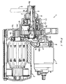
- Figure 1 is a sectional side view of an essential part of a starter for automobiles according to the present invention.
- Figure 1 is a sectional side view of an essential part of a starter 1 mounted on the engine of an automobile, taken along an axial line.
- This starter 1 is intended to drive an annular pinion gear 3 which is rotated by a motor 2 in such a manner that the pinion gear 3 may be selectively meshed with a ring gear 4 of the engine which is not shown in the drawings, and by turning on a magnetic switch 5 integrally provided in the starter 1 the shifting movement of the pinion gear 3 and the rotation of the motor 2 are both accomplished.
- a shift lever 7 consisting of a fork member which brings about an interaction between the armature 6 and the pinion gear 3 in such a manner that the pinion gear 3 undergoes a shifting movement in synchronism with the axial displacement of the armature 6.
- the pinion gear 3 is coaxially fitted on a pinion gear support shaft 8 extending in parallel with the axial line of the motor 2 and rotatably supported by a casing 1a of the starter 1, and is coupled with the pinion gear support shaft 8 by spline so as to transmit torque in circumferential direction and to be able to move freely in axial direction.
- This pinion gear support shaft 8 consists of a hollow shaft member, and coaxially accommodates therein a push rod 9.
- the rear end of the push rod 9 is provided with an external radial flange 9a, and is slidably and coaxially received in a sleeve member 10.
- One axial end of the sleeve member 10 associated with the external radial flange 9a of the push rod 9 is provided with an internal radial flange 10a which can engage with a shoulder surface of the external radial flange 9a facing the pinion gear 3, and a return spring 11 consisting of a compression coil spring is interposed between an annular internal shoulder surface 8a of the pinion gear support shaft 8 and an outer end surface of the internal radial flange 10a for urging the push rod 9 in the direction to retract the pinion gear 3.
- a circular disk-shaped spring retainer 14 In the rear end of the sleeve member 10 facing the shift lever 7 is received a circular disk-shaped spring retainer 14 so as to close the opening defined by the rear end of the sleeve member 10, and is prevented from moving out of the sleeve member 10 by inwardly crimping the circular rear edge 10b of the sleeve member 10.
- a shift spring 15 consisting of a compression coil spring is coaxially received in the sleeve member 10, and is pre-compressed with a certain load between the external radial flange 9a and the spring retainer 14. Therefore, in the illustrated initial condition, the external radial flange 9a and the internal radial flange 10a are placed in a mutually abutting condition by being elastically interposed between the return spring 11 and the shift spring 15.
- the armature 6 projects out of the magnetic switch 5 by being biased by an internally provided return spring not shown in the drawing, and the shift lever 7 having one of its ends engaged by a slot provided on the projected end of the armature 6 is engaged with the outer surface of the spring retainer 14 at its other end.
- the outer circumferential surface of the pinion gear support shaft 8 supports an input gear 12 in a freely rotatable manner, and a drive shaft 2a of the motor 2 and the pinion gear support shaft 8 are mutually coupled by a drive gear 2b mounted on the drive shaft 2a and meshing with the input gear 12.
- a one-way clutch 13 is provided between the input gear 12 and the pinion gear support shaft 8 for transmitting the torque applied to the input gear 12 to the pinion gear support shaft 8.
- the one-way clutch 13 has an output end securely fitted on the pinion gear support shaft 8 and an input end provided with an external gear while the input gear 12 is provided with an internal gear which meshes with the external gear of the input end of the one-way clutch 13.
- these external and internal gears form coupling means 16 which couples the input end and the input gear 12 in axially slidable but rotatively drivable relationship. This arrangement significantly facilitates the assembling of the starter 1.
- the switching action of the magnetic switch 5 causes electric current to be supplied to the motor 2, and a drive torque of the motor 2 is transmitted to the pinion gear support shaft 8 via the input gear 12 and the one-way clutch 13, thereby causing the pinion gear support shaft 8 to rotate along with the pinion gear 3. Therefore, the pinion gear 3 is pushed into meshing with the ring gear 4, and the ring gear 4 is then rotatively driven by the torque transmitted from the motor 2.
- the shift spring 15 is capable of achieving such a result is provided between the pinion gear 3 and the shift lever 7 or between the push rod 9 and the shift lever 7. Therefore, the shape of the shift lever 7 can be simplified without the shift lever 7 being required to be formed into a complicated shape for the purpose of mounting a torsion coil spring in a conventional manner. Further, since a compression coil spring can be used for the shift spring, and, in that case, it is possible to place the compression coil spring inside the sleeve member 10 having a cylindrical shape very easily. When the shift spring 15 is received in the sleeve member 10 as mentioned above, the action of the shift spring 15 can be stabilized because the shift spring 15 is favorably guided by the inner circumferential surface of the sleeve member 10.
- the shift spring since the shift spring is provided between the push rod or the pinion gear and the shift lever, and is therefore not required to be mounted on the shift lever, the shape of the shift lever can be simplified, and the efforts required for assembling the starter can be reduced.
- the shift spring consists of a compression coil which is coaxial with the push rod, the pinion gear and the pinion gear support member, the starter may be constructed in a highly compact manner, and the action of the shift spring may be stabilized.
Landscapes
- Engineering & Computer Science (AREA)
- Chemical & Material Sciences (AREA)
- Combustion & Propulsion (AREA)
- Mechanical Engineering (AREA)
- General Engineering & Computer Science (AREA)
- Connection Of Motors, Electrical Generators, Mechanical Devices, And The Like (AREA)
Claims (4)
- Démarreur pour un moteur à combustion interne, comprenant:un carter (1a) ;un moteur (2) fixé audit carter (1a);un arbre de support de pignons tubulaire (8) supporté, en vue de sa rotation, par ledit carter, et couplé à un arbre de commande dudit moteur, de manière à être entrainé de manière rotative par ledit moteur;un pignon annulaire (3) fixé sur ledit arbre de support de pignon en vue de son coulissement axial et de son entraînement en rotation, ledit pignon pouvant coulisser entre une position rétractée et une position sortie adaptée pour se mettre en prise avec une couronne dentée dudit moteur à combustion interne;un ressort de rappel (11) pour pousser en force ledit pignon vers ladite position rétractée;une tige de poussée (9) logée, en vue de son coulissement dans le sens axial, dans ledit arbre de support de pignons tubulaire et pourvue d'une extrémité libre en prise avec une extrémité libre dudit pignon pour transmettre une force de déplacement en vue d'entraîner ledit pignon depuis ladite position rétractée vers ladite position sortie;un levier basculant (7) supporté, en vue de son pivotement, par ledit carter pour transmettre ladite force de déplacement à partir d'un commutateur magnétique vers ladite tige de poussée; etun ressort de déplacement (15) placé entre une extrémité associée dudit levier basculant et une extrémité de base de ladite tige de poussée, caractérisé en ce que le ressort de déplacement (15) se compose d'un ressort hélicoïdal à compression, logé, de manière coaxiale, dans ledit arbre de support de pignons, et en ce que ladite extrémité de base de ladite tige de poussée est pourvue d'un rebord radial externe (9a), et ledit ressort de déplacement est logé, de manière coaxiale, dans un organe formant manchon (10) comportant un rebord radial interne (10a) en prise avec ledit rebord radial externe de ladite tige de poussée, ledit ressort de rappel se composant d'un ressort hélicoïdal à compression qui vient se loger de manière coaxiale entre ladite tige de poussée et ledit arbre de support de pignon, et est interposé entre une surface d'extrémité externe dudit rebord radial interne (10a) et une surface d'épaulement annulaire opposée (8a) définie dans ledit arbre de support de pignons.
- Démarreur selon la revendication 1, caractérisé en ce qu'un organe formant disque (14) vient se loger dans ledit organe formant manchon (10) et est interposé entre ladite extrémité associée dudit levier basculant (7) et une première extrémité dudit ressort de déplacement (15), ledit organe formant manchon étant pourvu de moyens (l0b) pour retenir ledit ressort de déplacement à l'intérieur dudit organe formant manchon en s'opposant à la force de décalage dudit ressort de déplacement, et une deuxième extrémité dudit ressort de décalage est en prise avec ledit rebord radial externe (9a).
- Démarreur selon la revendication 2, caractérisé en ce qu'il comprend, en outre, un pignon d'entrée annulaire (12) supporté, de manière coaxiale, autour dudit arbre de support de pignons, un embrayage unidirectionnel (13) étant interposé entre eux, et un engrenage de commande (2b), fixé sur ledit arbre de commande (2a) dudit moteur (2), se mettant en prise avec ledit pignon d'entrée (12).
- Démarreur selon la revendication 3, caractérisé en ce que ledit pignon d'entrée (12) est supporté en tournant librement sur ledit arbre de support de pignons (8), et ledit embrayage unidirectionnel (13) comporte une extrémité de sortie fixée correctement sur ledit arbre de support de pignons (8) et une extrémité d'entrée en prise avec ledit pignon d'entrée (12) via un moyen d'accouplement (16) qui accouple ladite extrémité d'entrée et ledit pignon d'entrée en vue de leur coulissement dans le sens axial et de leur entraînement en rotation.
Applications Claiming Priority (2)
| Application Number | Priority Date | Filing Date | Title |
|---|---|---|---|
| JP046851U JPH061777U (ja) | 1992-06-12 | 1992-06-12 | スタータ |
| JP46851/92 | 1992-06-12 |
Publications (2)
| Publication Number | Publication Date |
|---|---|
| EP0575105A1 EP0575105A1 (fr) | 1993-12-22 |
| EP0575105B1 true EP0575105B1 (fr) | 1996-07-24 |
Family
ID=12758849
Family Applications (1)
| Application Number | Title | Priority Date | Filing Date |
|---|---|---|---|
| EP93304532A Expired - Lifetime EP0575105B1 (fr) | 1992-06-12 | 1993-06-10 | Démarreur |
Country Status (6)
| Country | Link |
|---|---|
| US (1) | US5353658A (fr) |
| EP (1) | EP0575105B1 (fr) |
| JP (1) | JPH061777U (fr) |
| KR (1) | KR0131369Y1 (fr) |
| CA (1) | CA2098250A1 (fr) |
| DE (1) | DE69303777T2 (fr) |
Families Citing this family (10)
| Publication number | Priority date | Publication date | Assignee | Title |
|---|---|---|---|---|
| JPH0712034A (ja) * | 1993-06-23 | 1995-01-17 | Mitsuba Electric Mfg Co Ltd | スタータ |
| US5945755A (en) * | 1994-09-20 | 1999-08-31 | Denso Corporation | Starter with housing for cantilever-mounting on engine |
| JP3156589B2 (ja) * | 1995-07-17 | 2001-04-16 | 株式会社デンソー | エンジン始動装置 |
| JP2002125351A (ja) * | 2000-10-12 | 2002-04-26 | Moric Co Ltd | 内燃機関用スタータモータ |
| DE10208069C1 (de) * | 2002-02-25 | 2003-12-04 | Loos Juergen | Stellgetriebe |
| KR20040093588A (ko) * | 2003-04-30 | 2004-11-06 | 발레오전장시스템스코리아 주식회사 | 차량용 스타터 모터의 하우징 체결구조 |
| JP4380595B2 (ja) * | 2005-05-31 | 2009-12-09 | 株式会社デンソー | スタータ |
| US7584676B2 (en) * | 2007-04-18 | 2009-09-08 | Ingersoll Rand Company | Rear serviceable engine starter |
| CN104234901B (zh) * | 2013-06-13 | 2016-08-24 | 株式会社美姿把 | 起动器 |
| CN107152365B (zh) * | 2016-03-03 | 2021-04-30 | 德昌电机(深圳)有限公司 | 发动机、发动机启动器及其外壳总成 |
Family Cites Families (4)
| Publication number | Priority date | Publication date | Assignee | Title |
|---|---|---|---|---|
| NZ197213A (en) * | 1980-06-13 | 1983-09-30 | Reed International Ltd | Paint formulation water phase dispersed in an oil phase |
| CA1141994A (fr) * | 1980-09-13 | 1983-03-01 | Norimitsu Kurihara | Mecanisme sur demarreur |
| JPH0616986Y2 (ja) * | 1986-08-11 | 1994-05-02 | 本田技研工業株式会社 | エンジンの始動装置 |
| DE3874157T2 (de) * | 1987-01-23 | 1993-03-25 | Mitsubishi Electric Corp | Anlasser fuer verbrennungsmotor. |
-
1992
- 1992-06-12 JP JP046851U patent/JPH061777U/ja active Pending
-
1993
- 1993-05-26 KR KR2019930009001U patent/KR0131369Y1/ko not_active Expired - Fee Related
- 1993-06-10 US US08/075,078 patent/US5353658A/en not_active Expired - Lifetime
- 1993-06-10 EP EP93304532A patent/EP0575105B1/fr not_active Expired - Lifetime
- 1993-06-10 DE DE69303777T patent/DE69303777T2/de not_active Expired - Fee Related
- 1993-06-11 CA CA002098250A patent/CA2098250A1/fr not_active Abandoned
Also Published As
| Publication number | Publication date |
|---|---|
| US5353658A (en) | 1994-10-11 |
| CA2098250A1 (fr) | 1993-12-13 |
| DE69303777D1 (de) | 1996-08-29 |
| DE69303777T2 (de) | 1997-03-06 |
| EP0575105A1 (fr) | 1993-12-22 |
| JPH061777U (ja) | 1994-01-14 |
| KR940007946U (ko) | 1994-04-15 |
| KR0131369Y1 (ko) | 1998-12-15 |
Similar Documents
| Publication | Publication Date | Title |
|---|---|---|
| US4932273A (en) | Starter for an internal combustion engine | |
| US20060201266A1 (en) | Engine starter designed to have enhanced stability of engagement of pinion with ring gear | |
| US5044212A (en) | Coaxial engine starter | |
| US6708579B2 (en) | Reverse drive for a small vehicle | |
| EP0575105B1 (fr) | Démarreur | |
| JP3603508B2 (ja) | スタータ | |
| US5197342A (en) | Pinion stopper for starter | |
| JPH01187364A (ja) | スタータ装置 | |
| EP0631048B1 (fr) | Démarreur pour moteur à combustion interne | |
| JPH0264260A (ja) | 同軸形スタータ | |
| US5848551A (en) | Starter having improved pinion driving mechanism | |
| US4987786A (en) | Coaxial engine starter with spaced output shaft bearings | |
| EP0494681A1 (fr) | Dispositif de démarrage | |
| US5081875A (en) | Starter motor | |
| US4941366A (en) | Coaxial type starter device | |
| US4744258A (en) | Non-indexing engine starter gearing | |
| US4019393A (en) | Engine starter gearing | |
| JP3874707B2 (ja) | スタータ | |
| JPH06100169B2 (ja) | ピニオンシフト装置 | |
| AU685304B2 (en) | Engine starter gearing having improved grease retention | |
| EP0499955A1 (fr) | Dispositif de démarrage | |
| JP2529652B2 (ja) | 同軸形スタ―タ装置 | |
| JPH0648148Y2 (ja) | スタ−タ | |
| JPH0723580Y2 (ja) | スターターにおける緩衝装置 | |
| JPS60184965A (ja) | スタ−タ |
Legal Events
| Date | Code | Title | Description |
|---|---|---|---|
| PUAI | Public reference made under article 153(3) epc to a published international application that has entered the european phase |
Free format text: ORIGINAL CODE: 0009012 |
|
| AK | Designated contracting states |
Kind code of ref document: A1 Designated state(s): DE FR GB |
|
| 17P | Request for examination filed |
Effective date: 19940112 |
|
| 17Q | First examination report despatched |
Effective date: 19950120 |
|
| GRAH | Despatch of communication of intention to grant a patent |
Free format text: ORIGINAL CODE: EPIDOS IGRA |
|
| GRAH | Despatch of communication of intention to grant a patent |
Free format text: ORIGINAL CODE: EPIDOS IGRA |
|
| GRAA | (expected) grant |
Free format text: ORIGINAL CODE: 0009210 |
|
| AK | Designated contracting states |
Kind code of ref document: B1 Designated state(s): DE FR GB |
|
| REF | Corresponds to: |
Ref document number: 69303777 Country of ref document: DE Date of ref document: 19960829 |
|
| ET | Fr: translation filed | ||
| PGFP | Annual fee paid to national office [announced via postgrant information from national office to epo] |
Ref country code: GB Payment date: 19970513 Year of fee payment: 5 Ref country code: FR Payment date: 19970513 Year of fee payment: 5 |
|
| REG | Reference to a national code |
Ref country code: FR Ref legal event code: CD |
|
| PGFP | Annual fee paid to national office [announced via postgrant information from national office to epo] |
Ref country code: DE Payment date: 19970530 Year of fee payment: 5 |
|
| PLBE | No opposition filed within time limit |
Free format text: ORIGINAL CODE: 0009261 |
|
| STAA | Information on the status of an ep patent application or granted ep patent |
Free format text: STATUS: NO OPPOSITION FILED WITHIN TIME LIMIT |
|
| 26N | No opposition filed | ||
| PG25 | Lapsed in a contracting state [announced via postgrant information from national office to epo] |
Ref country code: GB Free format text: LAPSE BECAUSE OF NON-PAYMENT OF DUE FEES Effective date: 19980610 |
|
| GBPC | Gb: european patent ceased through non-payment of renewal fee |
Effective date: 19980610 |
|
| PG25 | Lapsed in a contracting state [announced via postgrant information from national office to epo] |
Ref country code: FR Free format text: LAPSE BECAUSE OF NON-PAYMENT OF DUE FEES Effective date: 19990226 |
|
| PG25 | Lapsed in a contracting state [announced via postgrant information from national office to epo] |
Ref country code: DE Free format text: LAPSE BECAUSE OF NON-PAYMENT OF DUE FEES Effective date: 19990401 |
|
| REG | Reference to a national code |
Ref country code: FR Ref legal event code: ST |