EP0575126A1 - Tête de réacteur à plasma et ensemble électrode - Google Patents
Tête de réacteur à plasma et ensemble électrode Download PDFInfo
- Publication number
- EP0575126A1 EP0575126A1 EP93304590A EP93304590A EP0575126A1 EP 0575126 A1 EP0575126 A1 EP 0575126A1 EP 93304590 A EP93304590 A EP 93304590A EP 93304590 A EP93304590 A EP 93304590A EP 0575126 A1 EP0575126 A1 EP 0575126A1
- Authority
- EP
- European Patent Office
- Prior art keywords
- passage
- cooling
- horizontal
- electrode
- extending
- Prior art date
- Legal status (The legal status is an assumption and is not a legal conclusion. Google has not performed a legal analysis and makes no representation as to the accuracy of the status listed.)
- Ceased
Links
- 238000001816 cooling Methods 0.000 claims abstract description 43
- 238000000034 method Methods 0.000 claims description 16
- 125000006850 spacer group Chemical group 0.000 claims description 11
- 238000005553 drilling Methods 0.000 claims description 10
- 238000003486 chemical etching Methods 0.000 claims description 7
- 239000004020 conductor Substances 0.000 claims description 5
- 239000000919 ceramic Substances 0.000 claims description 2
- 239000007787 solid Substances 0.000 claims 4
- VYPSYNLAJGMNEJ-UHFFFAOYSA-N Silicium dioxide Chemical compound O=[Si]=O VYPSYNLAJGMNEJ-UHFFFAOYSA-N 0.000 description 2
- 238000010586 diagram Methods 0.000 description 2
- 239000005350 fused silica glass Substances 0.000 description 2
- 239000000758 substrate Substances 0.000 description 2
- 229910000755 6061-T6 aluminium alloy Inorganic materials 0.000 description 1
- 229910000838 Al alloy Inorganic materials 0.000 description 1
- 239000005977 Ethylene Substances 0.000 description 1
- AZDRQVAHHNSJOQ-UHFFFAOYSA-N alumane Chemical group [AlH3] AZDRQVAHHNSJOQ-UHFFFAOYSA-N 0.000 description 1
- 238000010276 construction Methods 0.000 description 1
- 238000010924 continuous production Methods 0.000 description 1
- 239000002826 coolant Substances 0.000 description 1
- 230000001681 protective effect Effects 0.000 description 1
Images

Classifications
-
- H—ELECTRICITY
- H01—ELECTRIC ELEMENTS
- H01J—ELECTRIC DISCHARGE TUBES OR DISCHARGE LAMPS
- H01J37/00—Discharge tubes with provision for introducing objects or material to be exposed to the discharge, e.g. for the purpose of examination or processing thereof
- H01J37/32—Gas-filled discharge tubes
- H01J37/32009—Arrangements for generation of plasma specially adapted for examination or treatment of objects, e.g. plasma sources
-
- H—ELECTRICITY
- H01—ELECTRIC ELEMENTS
- H01J—ELECTRIC DISCHARGE TUBES OR DISCHARGE LAMPS
- H01J37/00—Discharge tubes with provision for introducing objects or material to be exposed to the discharge, e.g. for the purpose of examination or processing thereof
- H01J37/32—Gas-filled discharge tubes
- H01J37/32431—Constructional details of the reactor
- H01J37/32715—Workpiece holder
- H01J37/32724—Temperature
-
- H—ELECTRICITY
- H01—ELECTRIC ELEMENTS
- H01J—ELECTRIC DISCHARGE TUBES OR DISCHARGE LAMPS
- H01J2237/00—Discharge tubes exposing object to beam, e.g. for analysis treatment, etching, imaging
- H01J2237/32—Processing objects by plasma generation
- H01J2237/33—Processing objects by plasma generation characterised by the type of processing
- H01J2237/334—Etching
Definitions
- the present invention relates to a plasma reactor head assembly for a plasma assisted chemical etching reactor, and more particularly, to a plasma reactor head assembly designed to utilize a removable electrode having improved cooling surface area therein for use in a multi-axis plasma assisted chemical etching system.
- Prior art plasma assisted chemical etching reactor heads are not interchangeable, are relatively heavy and utilize a V-groove for cooling.
- the plasma reactor head assembly of the present invention presents an improvement over prior art reactor heads in that it provides an interchangeable head which is relatively light so as to allow multiple axes mounting and uses a removable electrode having larger cooling surface area therein for use with higher rf power.
- the present invention relates to a removable plasma reactor head electrode having an increased cooling surface area therein and a plasma reactor head assembly designed to accept the removable electrode.
- the increased cooling surface area is accomplished by lengthening the cooling passages within the electrode so as to more evenly distribute coolant within the electrode.
- the electrode is housed within a conically shaped main body of the plasma reactor head assembly.
- An insulative spacer and insulative upper core member are provided to secure the electrode within the main body.
- the electrode may be replaced with a larger or smaller electrode secured by corresponding insulative spacers and insulative upper core member.
- Another object of the present invention is to provide a lightweight reactor head assembly.
- One object of the present invention is to provide a plasma assisted chemical etching electrode with increased cooling capacity.
- Another object of the present invention is to provide a plasma assisted chemical etching electrode with higher rf power handling capability.
- Another object of the present invention is to provide a removable reactor head for a plasma assisted chemical etching reactor system.
- Another object of the present invention is to provide a removable reactor head receptive to a plurality of different sized removable electrodes.
- Another object of the present invention is to provide a lightweight reactor head assembly.
- Figure 1 is a schematic diagram showing a cross section of the reactor head assembly of the present invention along the plane of line 1-1 of Figure 2.
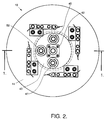
- Figure 2 is a schematic diagram showing a top view of the reactor head assembly of the present invention taken along the plane of 2-2 in Figure 1.
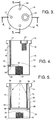
- Figure 3 is top view of the electrode of the present invention.
- Figure 4 is a cross section view of the electrode taken along the plane of line 4-4 in Figure 3.
- Figure 5 is a cross section view of the electrode taken along the plane of line 5-5 in Figure 3.
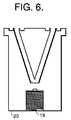
- Figure 6 is a cross section of a prior art electrode with a V-groove cooling passage taken along a plane equivalent to line 5-5 in Figure 3.
- Figure 1 shows a cross sectional view of the reactor head assembly 10 of the present invention taking along the line 1-1 of Figure 2.
- Figure 2 shows a top view of the reactor head assembly of the present invention taken along the line 2-2 of Figure 1.
- Figures 3, 4 and 5 show a top and two cross sectional views of the cylindrical electrode 12 used in the reactor head assembly of the present invention.
- the cylindrical electrode 12 has an upper surface 14 which extends past vertical walls 15 so as to form a flange load bearing surface 16 .
- a process gas passage 18 extends from the upper surface 14 at inlet 17 to a central threaded cavity 19 projecting inwardly toward the upper surface 14 from a bottom surface 20 .
- a rf conductive gas diffuser (not shown) is threaded into cavity 19 .
- the passage 18 is formed from the joining of a first vertical subpassage 22 to a first horizontal subpassage 24 .
- the horizontal subpassage is obtained by drilling radially into the electrode to a depth which makes contact with the centrally threaded cavity 19 .
- the vertical passage is obtained by drilling into the top surface 14 of the electrode to a depth so as to connect with the horizontal passage.
- a plug 26 is welded in place over a hole extending from the horizontal subpassage 24 so as to provide a continuous process gas flow passage starting from the inlet 17 , through the first vertical subpassage 22 , to the horizontal subpassage 24 and finally to the cavity 19 .
- a top threaded cavity 27 extends inwardly from the top surface 14 to provide a receptacle for rf power to the electrode.
- the electrode 12 has second and third vertical subpassages 28 and 30 joined to a second horizontal subpassage 32 so as to form a cooling passage 33 in the electrode having an inlet 34 and an outlet 36 extending through the top surface 14 .
- the second horizontal subpassage is formed by drilling through the walls 15 of the electrode 12 above the first horizontal subpassage 24 and the cooling passage is made continuous by plugs 38 welded into place at the walls 15 where the horizontal subpassage extends therethrough.
- the cooling passage allows greater dissipation of heat, and thus higher rf power (up to 250 watts), than a prior art V-groove type cooling channel as shown in Figure 6 due to the increased cooling surface area within the electrode 12 .
- the electrode 12 is contained within the interior of an annular main insulative body 40 having a conically shaped nose 41 .
- the conical shape of the nose permits the reactor head assembly of the present invention to be used more easily in multiple axes configurations than a square head design because the conical shape allows a greater degree of freedom for head placement when the electrode is in close proximity to a substrate located below.
- a 30° rise from the bore at the bottom of the main body to the bottom of the main body at the sides has been found sufficient for adequate head placement.
- the construction of the reactor head assembly is begun by attaching electrode 12 to an upper insulative core member 42 , machined from MecorTM, a machinable ceramic manufactured by Owens-Corning, by an insulative retaining ring 44 , machined from poly-tetra-fluro-ethylene (PTFE), which bears on the flange surface 16 .
- a rf power conductor 46 contained within the upper core member 42 which also extends through upper surface 43 is connected to the threaded cavity 27 of the electrode 12 .
- the upper core member also contains a large process gas passage 50 which also extends through upper surface 43 and is connected to the process gas inlet 17 of the electrode 12 .
- Supply and return cooling lines also within the upper core member are connected to the cooling inlet 34 and cooling outlet 36 and extend through upper surface 43 to inlet 45 and outlet 47 .
- a fused silica insulative spacer 54 is inserted into the bore of the main body and is supported by a portion of the main body having a reduced interior diameter.
- the spacer is dimensioned so as to have an outside diameter which remains constant and an inside diameter approximately equal to the diameter of the electrode in use.
- the electrode 12 and upper core member are inserted into the main body so that retaining ring 44 rests on a portion of the interior of the main insulative body 40 and an upper surface of the fused silica insulative spacer 54 .
- the use of the spacer eliminates the need for exchanging the entire main body 40 each time a different diameter electrode 12 is used.
- the spacer walls that define the spacer bore also define plasma chamber 51 .
- the main body 40 is positioned proximal to a cradle 53 .
- the cradle has a plurality of guide pins 55 and 57 for alignment with a plurality of bores 59 and 61 in the upper surface 70 of the main body.
- an insulative plug 43 machined from PTFE is placed around the portion of the rf conductor which extends beyond the upper surface of the upper core 42 .
- a supply of process gas is connected to the process gas passage 50 by an SAE/MS connector 52 .
- a 6061-T6 aluminum core head cap 56 is placed over the main body 40 and upper core 42 and the main body is secured to the cradle by several bolts.
- the rf conductor is then connected to a rf power source by a rf connector assembly 62 .
- Cooling supply and return lines are connected to cooling inlet 45 and cooling outlet 47 .
- a 3003-0 aluminum alloy protective bumper 64 may be placed over the exterior lower portion of the main body so as to protect the main body from accidental collisions with substrates.
- a plasma reactor head assembly which is lightweight, readily interchangeable, having an electrode which has greater cooling channel surface area for use with rf power up to 250 watts.
Landscapes
- Physics & Mathematics (AREA)
- Engineering & Computer Science (AREA)
- Plasma & Fusion (AREA)
- Chemical & Material Sciences (AREA)
- Analytical Chemistry (AREA)
- Plasma Technology (AREA)
- Chemical Vapour Deposition (AREA)
- ing And Chemical Polishing (AREA)
- Drying Of Semiconductors (AREA)
Applications Claiming Priority (2)
| Application Number | Priority Date | Filing Date | Title |
|---|---|---|---|
| US89980092A | 1992-06-17 | 1992-06-17 | |
| US899800 | 1992-06-17 |
Publications (1)
| Publication Number | Publication Date |
|---|---|
| EP0575126A1 true EP0575126A1 (fr) | 1993-12-22 |
Family
ID=25411582
Family Applications (1)
| Application Number | Title | Priority Date | Filing Date |
|---|---|---|---|
| EP93304590A Ceased EP0575126A1 (fr) | 1992-06-17 | 1993-06-14 | Tête de réacteur à plasma et ensemble électrode |
Country Status (4)
| Country | Link |
|---|---|
| EP (1) | EP0575126A1 (fr) |
| JP (1) | JPH0730469B2 (fr) |
| IL (1) | IL106017A0 (fr) |
| NO (1) | NO932221L (fr) |
Cited By (2)
| Publication number | Priority date | Publication date | Assignee | Title |
|---|---|---|---|---|
| WO2002009141A3 (fr) * | 2000-07-20 | 2002-06-20 | Tokyo Electron Ltd | Appareil de remplacement automatise d'une elctrode dans un systeme de traitement au plasma |
| US6753498B2 (en) | 2000-07-20 | 2004-06-22 | Tokyo Electron Limited | Automated electrode replacement apparatus for a plasma processing system |
Citations (2)
| Publication number | Priority date | Publication date | Assignee | Title |
|---|---|---|---|---|
| EP0165400A1 (fr) * | 1984-06-22 | 1985-12-27 | International Business Machines Corporation | Dispositif pour graver avec un plasma |
| US5074456A (en) * | 1990-09-18 | 1991-12-24 | Lam Research Corporation | Composite electrode for plasma processes |
-
1993
- 1993-06-14 IL IL106017A patent/IL106017A0/xx unknown
- 1993-06-14 EP EP93304590A patent/EP0575126A1/fr not_active Ceased
- 1993-06-16 NO NO932221A patent/NO932221L/no unknown
- 1993-06-17 JP JP5146521A patent/JPH0730469B2/ja not_active Expired - Lifetime
Patent Citations (2)
| Publication number | Priority date | Publication date | Assignee | Title |
|---|---|---|---|---|
| EP0165400A1 (fr) * | 1984-06-22 | 1985-12-27 | International Business Machines Corporation | Dispositif pour graver avec un plasma |
| US5074456A (en) * | 1990-09-18 | 1991-12-24 | Lam Research Corporation | Composite electrode for plasma processes |
Cited By (2)
| Publication number | Priority date | Publication date | Assignee | Title |
|---|---|---|---|---|
| WO2002009141A3 (fr) * | 2000-07-20 | 2002-06-20 | Tokyo Electron Ltd | Appareil de remplacement automatise d'une elctrode dans un systeme de traitement au plasma |
| US6753498B2 (en) | 2000-07-20 | 2004-06-22 | Tokyo Electron Limited | Automated electrode replacement apparatus for a plasma processing system |
Also Published As
| Publication number | Publication date |
|---|---|
| JPH0657456A (ja) | 1994-03-01 |
| NO932221D0 (no) | 1993-06-16 |
| JPH0730469B2 (ja) | 1995-04-05 |
| NO932221L (no) | 1993-12-20 |
| IL106017A0 (en) | 1993-10-20 |
Similar Documents
| Publication | Publication Date | Title |
|---|---|---|
| US8680426B2 (en) | High current electrode for a plasma arc torch | |
| US9199330B2 (en) | Hollow contact tip-diffuser for GMAW manual/robotic arc welding MIG guns | |
| KR100646915B1 (ko) | 플라즈마 토치용 노즐 | |
| KR100303959B1 (ko) | 플라즈마 건 헤드 | |
| US3823302A (en) | Apparatus and method for plasma spraying | |
| US20040079735A1 (en) | Plasma arc torch head connections | |
| US6525292B1 (en) | Cartridge for a plasma torch and plasma torch fitted therewith | |
| JPH08185996A (ja) | プラズマトーチ電極 | |
| BRPI0615685A2 (pt) | eletrodo de maçarico de plasma com configurações de inserção aperfeiçoadas | |
| KR20020013849A (ko) | 플라즈마 토치 카트리지 및 끼워진 플라즈마 토치 | |
| CN101541465A (zh) | 具有优化水冷却的等离子弧切割焊炬部件 | |
| EP0195409A2 (fr) | Torche à arc de plasma | |
| EP0575126A1 (fr) | Tête de réacteur à plasma et ensemble électrode | |
| CN113950869A (zh) | 用于液体冷却的等离子弧炬的可调节长度消耗件 | |
| US7265313B2 (en) | Method and apparatus for improved cooling of resistance welding cap | |
| JPH0594989U (ja) | 高周波加熱コイル | |
| RU2060130C1 (ru) | Плазмотрон | |
| JP2502134Y2 (ja) | 高周波加熱コイル給電用同軸管の接続構造 | |
| RU2088391C1 (ru) | Неплавящийся электрод для плазменно-дуговых процессов | |
| CN219818335U (zh) | 一种焊枪 | |
| KR20050108703A (ko) | 내벽 용사를 위한 비이송식 열플라즈마 토치 | |
| JPH0796370A (ja) | 内面肉盛溶接用プラズマトーチ | |
| SU1563932A1 (ru) | Устройство дл дуговой обработки металлов |
Legal Events
| Date | Code | Title | Description |
|---|---|---|---|
| PUAI | Public reference made under article 153(3) epc to a published international application that has entered the european phase |
Free format text: ORIGINAL CODE: 0009012 |
|
| AK | Designated contracting states |
Kind code of ref document: A1 Designated state(s): CH DE FR GB LI NL SE |
|
| 17P | Request for examination filed |
Effective date: 19940526 |
|
| 17Q | First examination report despatched |
Effective date: 19950531 |
|
| STAA | Information on the status of an ep patent application or granted ep patent |
Free format text: STATUS: THE APPLICATION HAS BEEN REFUSED |
|
| 18R | Application refused |
Effective date: 19951123 |