EP0575920B1 - Antriebssteuervorrichtung bei der die Antriebskraft erhöht wird, wenn ein Abwürgungszustand detektiert wird - Google Patents
Antriebssteuervorrichtung bei der die Antriebskraft erhöht wird, wenn ein Abwürgungszustand detektiert wird Download PDFInfo
- Publication number
- EP0575920B1 EP0575920B1 EP93109807A EP93109807A EP0575920B1 EP 0575920 B1 EP0575920 B1 EP 0575920B1 EP 93109807 A EP93109807 A EP 93109807A EP 93109807 A EP93109807 A EP 93109807A EP 0575920 B1 EP0575920 B1 EP 0575920B1
- Authority
- EP
- European Patent Office
- Prior art keywords
- vehicle
- speed
- traction control
- slip ratio
- control apparatus
- Prior art date
- Legal status (The legal status is an assumption and is not a legal conclusion. Google has not performed a legal analysis and makes no representation as to the accuracy of the status listed.)
- Expired - Lifetime
Links
- 238000000034 method Methods 0.000 claims description 88
- 230000008569 process Effects 0.000 claims description 83
- 238000001514 detection method Methods 0.000 claims description 44
- 230000004044 response Effects 0.000 claims description 2
- 230000000994 depressogenic effect Effects 0.000 claims 1
- 230000002401 inhibitory effect Effects 0.000 claims 1
- 230000001133 acceleration Effects 0.000 description 11
- 230000005540 biological transmission Effects 0.000 description 7
- 239000000446 fuel Substances 0.000 description 7
- 230000006870 function Effects 0.000 description 6
- 238000002347 injection Methods 0.000 description 6
- 239000007924 injection Substances 0.000 description 6
- 238000002485 combustion reaction Methods 0.000 description 3
- 238000010586 diagram Methods 0.000 description 3
- 230000003247 decreasing effect Effects 0.000 description 2
- 230000001419 dependent effect Effects 0.000 description 2
- 230000035945 sensitivity Effects 0.000 description 2
- 230000008859 change Effects 0.000 description 1
- 230000000694 effects Effects 0.000 description 1
- 235000021050 feed intake Nutrition 0.000 description 1
- 230000005484 gravity Effects 0.000 description 1
- 238000012986 modification Methods 0.000 description 1
- 230000004048 modification Effects 0.000 description 1
- 238000011144 upstream manufacturing Methods 0.000 description 1
Images




Classifications
-
- B—PERFORMING OPERATIONS; TRANSPORTING
- B60—VEHICLES IN GENERAL
- B60K—ARRANGEMENT OR MOUNTING OF PROPULSION UNITS OR OF TRANSMISSIONS IN VEHICLES; ARRANGEMENT OR MOUNTING OF PLURAL DIVERSE PRIME-MOVERS IN VEHICLES; AUXILIARY DRIVES FOR VEHICLES; INSTRUMENTATION OR DASHBOARDS FOR VEHICLES; ARRANGEMENTS IN CONNECTION WITH COOLING, AIR INTAKE, GAS EXHAUST OR FUEL SUPPLY OF PROPULSION UNITS IN VEHICLES
- B60K28/00—Safety devices for propulsion-unit control, specially adapted for, or arranged in, vehicles, e.g. preventing fuel supply or ignition in the event of potentially dangerous conditions
- B60K28/10—Safety devices for propulsion-unit control, specially adapted for, or arranged in, vehicles, e.g. preventing fuel supply or ignition in the event of potentially dangerous conditions responsive to conditions relating to the vehicle
- B60K28/16—Safety devices for propulsion-unit control, specially adapted for, or arranged in, vehicles, e.g. preventing fuel supply or ignition in the event of potentially dangerous conditions responsive to conditions relating to the vehicle responsive to, or preventing, spinning or skidding of wheels
Definitions
- the present invention relates to a traction control apparatus provided in an automotive vehicle according to the preamble of the patent claim 1.
- the driving force transmitted from the engine to the driving wheels of the vehicle is greater than the maximum friction force between the wheels and the road. Since the maximum friction force between the wheels and the snow road is low, the driving wheels of the vehicle undergo excessive slippage, and the vehicle may stall. On the snow road, the driving force (acting in a direction of vehicle movement) and the side force (acting in a direction lateral to the vehicle movement) are lowered, and the vehicle acceleration is so low that the vehicle running conditions are unstable.
- a traction control device for use in an automotive vehicle.
- a traction control process is performed in order to increase vehicle acceleration and straight line stability, thus preventing the driving wheels from undergoing excessive slippage when the vehicle starts running or when the vehicle is accelerating.
- a slip ratio can be defined to be a speed difference between a predetermined target rotational speed and the actual rotational speed of the driving wheels of the vehicle.
- a feedback control process for controlling the output torque of the engine is performed so as to maintain the slip ratio at a value smaller than a prescribed speed difference.
- this feedback control process performed to control the output torque of the engine is called the traction control process.
- the EP 0 320 007 discloses a traction control apparatus of this kind which comprises a determining means for determining a slip ratio of driving wheels and a drive torque control means coupled to the determining means for performing a traction control process such that the driving force is reduced when the slip ratio is greater than a predetermined slip ratio value. Furthermore, a detecting means is provided which detects whether or not an operation condition of the vehicle is a stalling condition. If the detecting means determines that the operation condition of the engine is a stalling condition the execution of the traction control processing is inhibited.
- the subject matter of the invention consists in that the traction control apparatus has determining means for determining a slip ratio of the driving wheels, drive torque control means coupled to the determining means for performing a traction control process in which a driving force applied to the driving wheels is controlled such that the driving force is reduced when the slip ratio determined by said determining means is greater than a predetermined slip ratio value, detecting means for detecting whether or not an operating condition of the vehicle is a stalling condition and changing means coupled to the drive torque control means and the detecting means for controlling the drive torque control means so that, when a stalling condition is detected by the detecting means, the driving force applied to the driving wheels is increased to prevent the vehicle from stalling, the predetermined slip ratio value is controlled by the changing means such that, when a stalling condition is detected by the detecting means, the predetermined slip ratio value is increased to prevent the vehicle from stalling wherein, when no stalling condition is detected, the driving
- the document JP 3-78541 teaches an apparatus in which the execution of a traction control processing and the time to start the operation of the engine is inhibited when the automatic transmission is stalling. Therefore, according to the teaching of this state of the art, the longitudinal direction driving force applied to the driving wheels of the vehicle would be considerably reduced if the execution of traction control processing is inhibited when a stalling condition is detected.
- the document EP-A-0 457 221 teaches an apparatus in which a traction control processing is performed by setting a corrected longitudinal direction acceleration according to changes in the longitudinal direction acceleration of the vehicle.
- a target driving torque is set by correcting a reference driving torque according to a slip amount of the driving wheels.
- the driving torque of the engine is controlled so that it is equal to the thus set target driving torque, thereby preventing a stalling feeling of the vehicle immediately after the speed shift.
- FIG.1 shows this traction control apparatus.
- a slip ratio determining part 11 a drive torque control part 12, a stall detecting part 13, and a changing part 14 are provided.
- the slip ratio determining part 11 determines a slip ratio of driving wheels of a vehicle.
- the drive torque control part 12 controls a driving force of the driving wheels such that the driving force is lowered to a smaller value when the slip ratio determined by the determining part 11 is greater than a reference value.
- the detecting part 13 detects a stalling condition of the vehicle.
- the changing part 14 changes the reference value of the drive torque control part 12 when a stalling condition is detected by the detecting part 13, so that the driving force of the driving wheels is increased due to the thus changed reference value.
- FIG.2 shows a rear-wheel-driven automotive vehicle 20 with an engine 21, an electronic control unit (ECU) 22, a microcomputer 23, and an automatic transmission 24.
- the automotive vehicle 20 has front wheels 25 and 26 which are driven-side wheels, and rear wheels 27 and 28 which are driving-side wheels.
- An output shaft of the engine 21 is coupled to a torque converter of the automatic transmission 24, and a driving power of the engine 21 is transmitted from the automatic transmission 24 to the rear wheels 27 and 28 via a drive shaft 29 so that the vehicle 20 is propelled and moved with the driving force of the rear wheels 27 and 28.
- wheel speed sensors 30 and 31 are provided at the front wheels 25 and 26 so as to sense the rotational speed of each of the front wheels, and wheel speed sensors 32 and 33 are provided at the rear wheels 27 and 28 so as to sense the rotational speed of the rear wheels.
- An engine speed sensor 34 is provided within the engine 21 to sense the rotational speed of the crankshaft of the engine 21. This rotational speed is called an engine speed.
- a signal indicating the engine speed being sensed is supplied from the engine speed sensor 34 to both the ECU 22 and the microcomputer 23. Signals indicating the wheel speeds sensed by the wheel speed sensors 30-33 are supplied to the microcomputer 23.
- a main throttle valve 40 and a sub-throttle valve 41 upstream from the main throttle valve 40 are provided in the intake pipe 35.
- a throttle position (or a throttle opening) of the main throttle valve 40 is adjusted in response to the position of an accelerator pedal 39 set by a vehicle operator, in order to control the flow rate of intake air.
- a throttle position of the sub-throttle valve 41 is adjusted by a throttle valve actuator 42 such as a stepping motor.
- the operation of the throttle valve actuator 42 is controlled by a signal output by the microcomputer 23.
- a throttle position sensor 43 is mounted to sense the throttle position of the main throttle valve 40, and outputs a signal indicating the throttle position to both the ECU 22 and the microcomputer 23.
- a throttle position sensor 44 is also mounted to sense the throttle position of the sub-throttle valve 41, and outputs a signal indicating the throttle position to both the ECU 22 and the microcomputer 23.
- the ECU 22 is made up of a digital computer, and carries out a fuel injection control process and an ignition timing control process.
- a fuel injection valve 45 is provided in the intake manifold 37 so as to inject fuel into the combustion chamber 38 during an injection time. In order to determine this injection time, the fuel injection control process is carried out by the ECU 22 in accordance with the signals supplied from the engine speed sensor 34, the throttle position sensors 43, 44, and other sensors (not shown in FIG.2).
- a spark plug 46 is provided in the combustion chamber 38. In order to determine an ignition timing of the spark plug 46, the ignition timing control process is carried out by the ECU 22 in accordance with the signals supplied from the above mentioned sensors.
- the ECU 22 carries out a shifting control process in accordance with the throttle position signal supplied from the main throttle sensor 43, a signal indicating the current shift position supplied from the automatic transmission 24, a signal indicating the vehicle speed supplied from a vehicle speed sensor (not shown), and a prescribed control signal supplied from the microcomputer 23.
- This shifting control process is carried out in order to set a shift position of the automatic transmission 24 which position is appropriate for the vehicle running conditions.
- a traction control process is carried out by the microcomputer 23.
- the engine speed signal supplied from the engine speed sensor 34, the wheel speed signals supplied from the wheel speed sensors 30-33, and the throttle position signals supplied from the throttle position sensors 43-44 are input to the microcomputer 23.
- the microcomputer 23 carries out a drive torque control process for controlling the drive torque of the engine 21.
- the microcomputer 23 controls the operation of the throttle valve actuator 42 based on the result of the drive torque control process, so that the throttle position of the sub-throttle valve 41 is adjusted, thus controlling the drive torque of the engine 21.
- Signals supplied from the microcomputer 23 to the ECU 22 include: a TRC signal indicating whether the traction control process is being performed, a fuel cut signal indicating the fuel cut of the fuel injection valve 45, and an ignition timing delay signal indicating the delay of ignition timing of the spark plug 46.
- the drive torque of the engine 21 during the traction control process is controlled by setting a throttle position of the sub-throttle valve 41 to an appropriate position in accordance with the slipping conditions of the driving wheels. Also, the throttle position Ts of the sub-throttle valve 41 is determined in accordance with a slip ratio dV of the rear wheels 27 and 28 (the driving wheels), as follows.
- Ts(n) denotes the throttle position of the sub-throttle valve 41 to be determined
- Ts(n-1) denotes the previous throttle position of the sub-throttle valve 41 being previously set
- To denotes a period on which the traction control process is repeatedly performed.
- FIGS.3A and 3B show the traction control process. This process is repeatedly performed by the microcomputer 23 every 12 ms (milliseconds). By performing the traction control process shown in FIGS.3A and 3B, the functions of the slip rate determining part 11, the drive torque control part 12 and the changing part 14 according to the present invention are achieved.
- step 100 detects whether or not the execution conditions for starting the traction control process are satisfied.
- the execution conditions include: 1) the throttle position Tm of the main throttle valve 40 is not at its fully-closed position, and 2) none of the above mentioned sensors are malfunctioning. If any of the execution conditions are not satisfied, step 120 shown in FIG.3B is performed and the traction control process ends.
- flags FS and CEND (which will be described below) are reset to zero and the throttle position Ts of the sub-throttle valve 41 is set to a maximum throttle position Tsmax.
- the maximum throttle position Tsmax indicates a fully-open throttle position of the sub-throttle valve 41.
- step 100 If the execution conditions are satisfied in step 100, the reading of speed parameters from the sensors and the associated calculations are performed in steps 102-107.
- the driven-wheel speeds Vfr and Vfl are indicated by the signals output by the sensors 30 and 31.
- Step 103 sets a target speed Vt3 of the rear wheels 27 and 28 (the driving wheels) based on the value of the vehicle speed Vto set in step 102.
- the target speed Vt3 is calculated in accordance with the conditions and calculations indicated in FIG.4A:
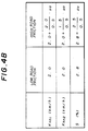
- the coefficients Knn1 and Knn2 and the target slip ratio S are set to values indicated in FIG.4B.
- the values being set are either one of two different values: one value used when the friction force between the wheel and the road is relatively low, and the other used when the road friction force is relatively high.
- the vehicle acceleration "a” in the above equation (3) is calculated from the changing rate of the rotational speeds Vfl and Vfr of the front wheels 25 and 26 indicated by the output signals of the sensors 30 and 31.
- the vehicle acceleration "a” is set to the value indicated by a signal output by an acceleration sensor (not shown).
- the target speed Vt3 of the driving wheels is set, in step 103, so as to be greater than the vehicle speed Vto of the driven wheels, thus the vehicle 20 undergoes a desired slippage.
- the target slip ratio S has a relatively small value, and the preferential traction control is given to the side force, rather than the driving force, thus ensuring increased straight line stability of the vehicle.
- the target speed Vt3 determined in step 103 has a value substantially indicating the value of a slip ratio of the driving wheels, and the function of the determining part 11 is achieved by performing step 103.
- Step 106 sets a start speed Vtb at which the performing of the traction control process is started.
- the coefficient B is preset to a value dependent on the vehicle speed and the road condition.
- the start speed Vtb is set to a value that is greater than the target speed Vt3, in order to avoid performing too frequently the traction control process.
- TRC traction control
- Step 109 detects whether or not the driving wheel speed Vd is greater than the start speed Vtb. If Vd ⁇ Vtb, the driving wheel speed Vd does not reach the start speed Vtb at which the traction control process is started. Then, the step 120 shown in FIG.3B is performed to reset both the flags FS and CEND to zero and set the throttle position Ts of the sub-throttle valve 41 to the maximum throttle position Tsmax.
- Step 110 sets the TRC execution flag FS to 1 (FS ⁇ -- 1).
- Step 111 sets the throttle position Ts of the sub-throttle valve 41 to an initial throttle position f(NE) (Ts ⁇ -- f(NE)).
- the initial throttle position f(NE) of the sub-throttle valve 41 is a value determined in accordance with the road condition and the engine speed NE indicated by the output signal of the engine speed sensor 34.
- the sub-throttle valve 41 is always set to the fully-open throttle position while the traction control process is not being performed. If the traction control process is started with the sub-throttle valve 41 set at the fully-open throttle position, a certain time is needed for the sensitivity to the change in the throttle position of the sub-throttle valve 41 becoming appreciable. In order to obtain a reasonable sensitivity immediately when the traction control process is started, the sub-throttle valve 41 is set to the initial throttle position f(NE) in step 111.
- step 112 a feedback control procedure in which the throttle position Ts of the sub-throttle valve 41 is adjusted to a target throttle position is started after the initial throttle position f(NE) is reached. If the feedback control procedure is performed before the initial throttle position is reached, the throttle position will be adjusted to an excessive value. In order to avoid this, step 112 is performed.
- Step 113 sets a correction amount dTs used to determine a target throttle position Ts of the sub-throttle valve 41.
- Step 114 sets a target throttle position Ts of the sub-throttle valve 41 based on the previous target throttle position Ts(n-1) and the correction amount dTs, both stored in a memory of the microcomputer 23.
- the target throttle position Ts is determined in accordance with the equation (1).
- a signal indicating the target throttle position Ts is supplied from the microcomputer 23 to the throttle valve actuator 42 to control the operation of the sub-throttle valve 41.
- Step 115 detects whether or not the throttle position Ts of the sub-throttle valve 41 is greater than a throttle position Tm of the main throttle valve 40. If the answer to step 115 is negative, step 119 is performed, and then the traction control process ends. Step 119 resets a time counter CEND to zero.
- step 116 detects whether or not the absolute value of the speed difference (Vt3 - Vd) (which is defined to be the slip rate) is less than a prescribed value "d". If the answer to step 116 is negative, step 119 is performed. If the answer to step 116 is affirmative, step 117 is performed. Step 117 increments the time counter CEND (CEND ⁇ -- CEND + 1).
- step 118 detects whether or not the time counter CEND is greater than a prescribed time D. If the time counter CEND is greater than the prescribed time D, it is judged that all the traction control end conditions are satisfied. Then, the above step 120 is performed, and the traction control process ends. If the answer to step 118 is negative, the traction control process ends without performing other steps.
- the value d in step 116 and the time D in step 118 vary depending on the type of the vehicle to which the traction control apparatus according to the present invention is applied.
- the function of the drive torque control part 12 according to the present invention is achieved by performing steps 108-119 by means of the microcomputer 23 together with the sub-throttle valve 41 and the throttle valve actuator 41.
- a TRC signal indicating the value of the TRC execution flag FS being set in step 110 of the traction control process is supplied from the microcomputer 23 to the ECU 22 by a transmission unit (not shown).
- FIG.5 shows the driving force characteristics indicated by a curve I and the side force characteristics indicated by a curve II when the slip ratio varies.
- the driving force has a peak when the slip ratio is equal to a certain value Sm, the driving force increasing when the slip ratio is smaller than the value Sm, and the driving force decreasing when the slip ratio is greater than the value Sm.
- the side force is decreasing when the slip ratio is increasing.
- the traction control process described above is performed by giving a consideration to the balance of the driving force and the side force.
- a feedback control procedure in which the throttle position of the sub-throttle valve 41 is adjusted to a target throttle position is performed in a manner such that the slip ratio is within a normal range indicated by III in FIG.5.
- the target speed Vt3 of the driving wheels is determined in step 103.
- the throttle position corresponding to the target speed Vt3 is set to the sub-throttle valve 41, it is likely that the vehicle will stall when the vehicle is running on a snow road or uphill road, as previously described.
- a stall detection process is repeatedly performed by the microcomputer 23.
- the target speed Vt3 of the driving wheels is changed by performing steps 104 and 105 of the traction control process shown in FIG.3A so as to increase the driving force.
- FIGS.6A and 6B show the stall detection process.
- the stall detection process is repeatedly performed by the microcomputer 23 every 48 ms (milliseconds).
- the function of the stall detecting part 13 according to the present invention is achieved.
- step 203 detects whether or not the throttle position of the main throttle valve 40 which is responsive to the position of the accelerator pedal 39 is greater than the value of 30 degrees. In this step, it is judged whether the vehicle operator intends to accelerate the vehicle.
- step 214 When all the three conditions of the above steps 201-203 are satisfied, subsequent steps are performed to carry out the stall detecting procedure according to the present invention. When any of these conditions is not satisfied, step 214 shown in FIG.6B is performed without performing the subsequent steps. Step 214 resets the detection flag FCLIM to 0. After step 214 is performed, step 215 is performed and the stall detecting process ends.
- the detection flag FCLIM is set to zero.
- the detection flag FCLIM is set to 1 in the stall detection process. Conversely, when it is judged that the vehicle is not stalling, the detection flag FCLIM is set to zero.
- Step 215 resets both a detection counter CTCLM and a cancellation counter CTCLMCN to 0, and then the stall detecting process ends.
- FIG.7A shows the changes of the vehicle speed Vto when the stall detecting process is being performed.
- step 205 detects that the vehicle speed Vto sensed by the sensors 30-31 is smaller than the previous vehicle speed Vto(n-1) stored in the memory of the microcomputer 23.
- step 208 increments the detection counter CTCLM each time the stall detecting process is performed.
- step 204 detects whether or not the current vehicle speed Vto sensed by the sensors 30-31 is smaller than the previous vehicle speed Vto(n-1) being previously set and stored in the memory.
- Vto ⁇ Vto(n-1) it is judged that the vehicle is not stalling.
- Step 215 resets both the detection counter CTCLM and CTCLMCN to zero, and the stall detecting process ends.
- Vto ⁇ Vto(n-1) it is judged that the vehicle is possibly stalling.
- Step 206 is performed to detect whether or not the detection counter CTCLM is equal to zero.
- step 207 is performed to set a reference vehicle speed Vtorv by adding a given speed value (equal to 2 km/h) to the currently set vehicle speed Vto ( Vtorv ⁇ -- Vto + 2 km/h ).
- Step 208 increments the detection counter CTCLM (CTCLM ⁇ -- CTCLM + 1).
- Step 210 sets the detection flag FCLIM to the value one (FCLIM ⁇ -- 1). In the above step 215, the detection counter CTCLM and the cancellation counter CTCLMCN are reset to 0. If CTCLM ⁇ 5 in step 209, the stall detecting process ends without performing other steps.
- FIG.7B shows the changes of the value of the detection counter CTCLM when the stall detecting process described above is being performed.
- step 204 detects that the value of the detection flag FCLIM is equal to 1. If the answer to step 204 is affirmative, subsequent steps 211-213 are performed so as to cancel the performance of the stall detecting process.
- Step 211 detects whether or not the vehicle speed Vto is greater than the reference vehicle speed Vtorv being previously set in step 207. If the answer to step 211 is negative (Vto ⁇ Vtorv), the above step 215 is performed, and then the stall detecting process ends.
- Step 212 increments the cancellation counter CTCLMCN (CTCLMCN ⁇ -- CTCLMCN + 1).
- FIGS.7C and 7D respectively show the changes of the values of the detection flag FCLIM and cancellation counter CTCLMCN when the stall detecting process described above is being performed.
- the detection flag FCLIM is set to 1.
- the condition in which the detection flag FCLIM is equal to 1 continues for a time period indicated by an arrow "B" in FIG.7C, and during this period the stall detecting procedure is performed.
- the detection flag FCLIM is reset to 0, and the cancellation counter CTCLMCN is reset to 0.
- Step 105 adds the value of 3 km/h to the target vehicle speed Vt3 so that the target vehicle speed Vt3 is increased.
- the driving force of the vehicle is increased when a stalling condition is detected during the traction control process. It is possible to stably prevent the vehicle from stalling or undergoing a loss of the power of the engine when the vehicle is running on a snow road or uphill road. Also, in the above embodiment of the traction control apparatus, it is possible to prevent the vehicle from laterally slipping when the vehicle starts to turn around. Generally, when the vehicle is turning around, a predicted road friction force is reduced and the driving force in the vehicle front/rear direction is reduced so that the target vehicle speed Vt3 is likely to be lowered.
- the stall detection process is performed when the vehicle speed is within a low speed range between 5 km/h and 30 km/h. Even when the vehicle is turning, the target speed Vt3 of the driving wheels is increased when a stalling condition is detected.
- a traction control apparatus provided in another vehicle in which the vehicle stability during turning is increased, it is necessary to inhibit the performing of the stall detection process when the vehicle is turning. In this case, it is possible to quickly detect a stalling condition because the stall detection process can be performed if the vehicle speed is at a relatively high level.
- the road friction force is calculated in step 103 in FIG. 3A while the stall detection process is being performed.
- the detection flag FCLIM is equal to 1.
- the present invention is not limited to the above described embodiment, and several variations and modifications may be made.
- the changing part 14 according to the present invention may be replaced by a different means for increasing or widening a throttle opening of the sub-throttle valve 41 when a stalling condition is detected, or by another means for advancing an ignition timing of the spark plug 46 when a stalling condition is detected.
- a traction control apparatus includes a determining part (11) for determining a slip ratio of driving wheels (27, 28) of a vehicle (20), a drive torque control part (12) for performing a traction control process in which a driving force of the driving wheels is controlled such that the driving force is lowered to a smaller value when the slip ratio determined by the determining part (11) is greater than a reference value, a detecting part (13) for detecting a stalling condition of the vehicle, and a changing part (14) for changing the traction control process performed by the drive torque control part (12) when a stalling condition is detected by the detecting part (13), so as to increase the driving force of the driving wheels.
Landscapes
- Engineering & Computer Science (AREA)
- Chemical & Material Sciences (AREA)
- Combustion & Propulsion (AREA)
- Transportation (AREA)
- Mechanical Engineering (AREA)
- Control Of Vehicle Engines Or Engines For Specific Uses (AREA)
- Combined Controls Of Internal Combustion Engines (AREA)
- Auxiliary Drives, Propulsion Controls, And Safety Devices (AREA)
Claims (12)
- Traktionsregelgerät, das in einem Automobil (Fahrzeug) vorgesehen ist, wobei das Fahrzeug einen Motor und eine Vielzahl von Antriebsräder umfaßt, wobei das Traktionsregelgerät folgende Einrichtungen aufweist:dadurch gekennzeichnet, daßeine Ermittlungseinrichtung (11) zum Ermitteln eines Schlupfverhältnisses der Antriebsräder;eine Antriebsdrehmomentregeleinrichtung (12), die mit der Ermittlungseinrichtung (11) gekoppelt ist, um einen Traktionsregelvorgang auszuführen, bei dem eine auf die Antriebsräder aufgebrachte Antriebskraft derart geregelt wird, daß die Antriebskraft reduziert wird, wenn das durch die Ermittlungseinrichtung ermittelte Schlupfverhältnis größer als ein vorgegebener Schlupfverhältniswert ist;eine Erfassungseinrichtung (13), um zu erfassen, ob ein Betriebszustand des Fahrzeugs (20) ein Abwürgzustand ist oder nicht; undeine Änderungseinrichtung (14), die mit der Antriebsdrehmomentregeleinrichtung und der Erfassungseinrichtung gekoppelt ist, um die Antriebsdrehmomentregeleinrichtung so zu regeln, daß die auf die Antriebsräder aufgebrachte Antriebskraft erhöht wird, wenn ein Abwürgzustand durch die Erfassungseinrichtung erfaßt wird, um das Steckenbleiben des Fahrzeugs zu verhindern,
der vorgegebene Schlupfverhältniswert durch die Änderungseinrichtung (14) derart geregelt wird, daß der vorgegebene Schlupfverhältniswert erhöht wird, wenn ein Abwürgzustand durch die Erfassungseinrichtung (13) erfaßt wird, um das Steckenbleiben des Fahrzeugs zu verhindern, und so geregelt wird, daß die auf die Antriebsräder aufgebrachte Antriebskraft unterhalb einem maximalen Antriebskraftwert gehalten wird und eine auf die Antriebsräder aufgebrachte Seitenführungskraft über einem vorgegebenen Seitenführungskraftwert gehalten wird, wenn kein Abwürgzustand erfaßt wird. - Traktionsregelgerät nach Anspruch 1, dadurch gekennzeichnet, daß die Änderungseinrichtung (14) die Antriebsdrehmomentregeleinrichtung durch Ermitteln des vorgegebenen Schlupfverhältniswerts regelt, wenn ein Abwürgzustand des Fahrzeugs erfaßt wird, so daß die auf die Antriebsräder aufgebrachte Antriebskraft erhöht wird.
- Traktionsregelgerät nach Anspruch 1, dadurch gekennzeichnet, daß die Erfassungseinrichtung (13) nur dann erfaßt, ob ein Betriebszustand des Fahrzeugs ein Abwürgzustand ist, wenn ein Gaspedal (39) des Fahrzeugs niedergedrückt ist.
- Traktionsregelgerät nach Anspruch 1, wobei das Fahrzeug des weiteren eine Vielzahl von freilaufenden Rädern (25, 26) umfaßt, und wobei das Traktionsregelgerät des weiteren folgendes umfaßt: eine Vielzahl von Drehzahlsensoren (30, 31), wobei jeder Drehzahlsensor mit einem entsprechenden freilaufenden Rad des Fahrzeugs gekoppelt ist, um eine Drehzahl des jeweiligen freilaufenden Rads zu erfassen, eine Einrichtung zum Berechnen einer Fahrzeuggeschwindigkeit auf der Grundlage der Drehzahlen der freilaufenden Räder, die durch die Drehzahlsensoren wahrgenommen werden, und einen Speicher zum Speichern der berechneten Fahrzeuggeschwindigkeit, dadurch gekennzeichnet, daß die Erfassungseinrichtung (13) einen Abwürgzustand des Fahrzeugs erfaßt, wenn die aktuell berechnete Fahrzeuggeschwindigkeit kleiner geblieben ist als eine vorher berechnete Fahrzeuggeschwindigkeit, die für eine vorgegebene Zeitspanne in dem Speicher gespeichert ist.
- Traktionsregelgerät nach Anspruch 1, wobei das Fahrzeug des weiteren eine Vielzahl von freilaufenden Rädern (25, 26) umfaßt, und wobei das Traktionsregelgerät des weiteren folgendes umfaßt: eine Vielzahl von Drehzahlsensoren (30, 31), wobei jeder Drehzahlsensor mit einem entsprechenden freilaufenden Rad des Fahrzeugs gekoppelt ist, um eine Drehzahl des jeweiligen freilaufenden Rads zu erfassen, und eine Einrichtung zum Berechnen einer Fahrzeuggeschwindigkeit auf der Grundlage der Drehzahlen der freilaufenden Räder, die durch die Drehzahlsensoren wahrgenommen werden, dadurch gekennzeichnet, daß die Erfassungseinrichtung (13) erfaßt, ob ein Betriebszustand des Fahrzeugs ein Abwürgzustand ist, wenn die aktuell berechnete Fahrzeuggeschwindigkeit über einem unteren Ansprechwert und unter einem oberen Ansprechwert liegt.
- Traktionsregelgerät nach Anspruch 1, wobei das Traktionsregelgerät des weiteren eine Einrichtung zum Erfassen einer Fahrzeuggeschwindigkeit umfaßt, dadurch gekennzeichnet, daß die Ermittlungseinrichtung (11) das Schlupfverhältnis der Antriebsräder durch einen Vergleich einer Soll-Umdrehungsgeschwindigkeit der Antriebsräder mit der erfaßten Fahrzeuggeschwindigkeit ermittelt.
- Traktionsregelgerät nach Anspruch 1, wobei das Fahrzeug des weiteren eine Drosselklappe (41) umfaßt, und wobei die Antriebsdrehmomentregeleinrichtung (12) einen Rückführregelvorgang ausführt, bei dem eine Soll-Position der Drosselklappe auf der Grundlage einer vorherigen Soll-Drosselposition eingerichtet wird, wenn das durch die Ermittlungseinrichtung ermittelte Schlupfverhältnis nicht größer als der vorgegebene Schlupfverhältniswert ist, dadurch gekennzeichnet, daß die Antriebsdrehmomentregeleinrichtung (12) die auf die Antriebsräder aufgebrachte Antriebskraft durch Hemmen der Ausführung des Rückführregelvorgangs reduziert, wenn das durch die Ermittlungseinrichtung (11) ermittelte Schlupfverhältnis größer als der vorgegebene Schlupfverhältniswert ist.
- Traktionsregelgerät nach Anspruch 1, wobei das Fahrzeug des weiteren eine in einem Ansaugkanal des Motors vorgesehene Drosselklappe (41) umfaßt, dadurch gekennzeichnet, daß die Antriebsdrehmomentregeleinrichtung (12) die auf die Antriebsräder aufgebrachte Antriebskraft regelt, indem sie regelmäßig einen Rückführregelvorgang ausführt, wenn das Schlupfverhältnis nicht größer als der vorgegebene Schlupfverhältniswert ist, wobei eine Soll-Position Ts(n) der Drosselklappe auf der Grundlage einer vorherigen Soll-Drosselposition Ts(n-1) und einem Korrekturbetrag Dts in Übereinstimmung mit der Gleichung:
- Traktionsregelgerät nach Anspruch 1, wobei das Fahrzeug des weiteren eine in einem Ansaugkanal des Motors vorgesehene Drosselklappe (41) umfaßt, dadurch gekennzeichnet, daß die Antriebsdrehmomentregeleinrichtung (12) ein Drosselklappenstellglied (42) aufweist, um eine Position der Drosselklappe in Übereinstimmung mit einem Drosselpositionseingangssignal in das Drosselklappenstellglied einzustellen.
- Traktionsregelgerät nach Anspruch 1, dadurch gekennzeichnet, daß die Erfassungseinrichtung eine Erfassungsmarke einrichtet, wenn die Erfassungseinrichtung (13) erfaßt, daß der Betriebszustand des Fahrzeugs ein Abwürgzustand ist, und daß die Änderungseinrichtung (14) den vorgegebenen Schlupfverhältniswert ändert, wenn die Erfassungsmarke eingerichtet ist.
- Traktionsregelgerät nach Anspruch 1, wobei das Traktionsregelgerät des weiteren eine Einrichtung zum Erfassen einer Fahrzeuggeschwindigkeit und eine Einrichtung zum Erfassen eines Straßenzustands umfaßt, wobei die Ermittlungseinrichtung eine Soll-Geschwindigkeit der Antriebsräder auf der Grundlage des vorgegebenen Schlupfverhältniswerts berechnet, dadurch gekennzeichnet, daß die Änderungseinrichtung (14) den vorgegebenen Schlupfverhältniswert regelt, indem sie einen vorgegebenen Geschwindigkeitswert zu der Soll-Geschwindigkeit der Antriebsräder addiert, wenn ein Abwürgzustand durch die Erfassungseinrichtung (13) erfaßt wird, wobei die Soll-Geschwindigkeit durch die Ermittlungseinrichtung (11) auf der Grundlage der Fahrzeuggeschwindigkeit und dem erfaßten Straßenzustand ermittelt wird, und daß das neu vorgegebene Schlupfverhältnis einem Wert aus der Addition der Soll-Geschwindigkeit mit dem vorgegebenen Geschwindigkeitswert entspricht.
- Traktionsregelgerät nach Anspruch 1, dadurch gekennzeichnet, daß das Fahrzeug mit einer ersten Drosselklappe (40), die ansprechend auf eine durch einen Fahrer eingerichtete Position eines Gaspedals (39) betätigt wird, und einer zweiten Drosselklappe (41) versehen ist, die in Übereinstimmung mit einer Soll-Drosselposition betätigt wird, die durch die Antriebsdrehmomentregeleinrichtung (12) ermittelt wird.
Applications Claiming Priority (2)
| Application Number | Priority Date | Filing Date | Title |
|---|---|---|---|
| JP163124/92 | 1992-06-22 | ||
| JP16312492A JP3216235B2 (ja) | 1992-06-22 | 1992-06-22 | 加速スリップ制御装置 |
Publications (2)
| Publication Number | Publication Date |
|---|---|
| EP0575920A1 EP0575920A1 (de) | 1993-12-29 |
| EP0575920B1 true EP0575920B1 (de) | 1998-02-25 |
Family
ID=15767645
Family Applications (1)
| Application Number | Title | Priority Date | Filing Date |
|---|---|---|---|
| EP93109807A Expired - Lifetime EP0575920B1 (de) | 1992-06-22 | 1993-06-18 | Antriebssteuervorrichtung bei der die Antriebskraft erhöht wird, wenn ein Abwürgungszustand detektiert wird |
Country Status (4)
| Country | Link |
|---|---|
| US (1) | US5459661A (de) |
| EP (1) | EP0575920B1 (de) |
| JP (1) | JP3216235B2 (de) |
| DE (1) | DE69317073T2 (de) |
Families Citing this family (10)
| Publication number | Priority date | Publication date | Assignee | Title |
|---|---|---|---|---|
| DE4430108B4 (de) * | 1994-08-25 | 2011-11-24 | Robert Bosch Gmbh | Antriebsschlupfregelsystem |
| JP2967395B2 (ja) * | 1994-11-18 | 1999-10-25 | 本田技研工業株式会社 | 車両の前後グリップ力推定装置及び車両の駆動輪トルク制御装置 |
| JP3448995B2 (ja) * | 1994-12-01 | 2003-09-22 | 日産自動車株式会社 | 車両の駆動力制御装置 |
| JP4020536B2 (ja) * | 1999-06-08 | 2007-12-12 | トヨタ自動車株式会社 | 車輪速センサ異常検出装置 |
| DE10247243B4 (de) * | 2001-10-11 | 2015-03-26 | Continental Teves Ag & Co. Ohg | Verfahren zur Verbesserung einer Antriebsschlupfregelung |
| JP4531319B2 (ja) * | 2002-02-12 | 2010-08-25 | 日立オートモティブシステムズ株式会社 | 四輪駆動車の駆動力配分制御装置 |
| US7486489B2 (en) * | 2003-05-13 | 2009-02-03 | Siemens Canada Limited | System and method for speed control and stall protection combination for electric motors such as in engine cooling applications |
| US7499787B2 (en) * | 2004-10-07 | 2009-03-03 | Ford Global Technologies, Llc | Traction control system and method for a vehicle |
| US8442735B2 (en) * | 2005-06-15 | 2013-05-14 | Ford Global Technologies, Llc | Traction control system and method |
| US8689920B2 (en) * | 2009-12-28 | 2014-04-08 | Kawasaki Jukogyo Kabushiki Kaisha | Traction control system and method of suppressing driving power |
Family Cites Families (14)
| Publication number | Priority date | Publication date | Assignee | Title |
|---|---|---|---|---|
| AU620506B (en) * | 1906-06-19 | 1906-10-02 | Roland Lucien | An elastic substance similar to indiarubber and its method of manufacture |
| JPS60128055A (ja) * | 1983-12-14 | 1985-07-08 | Nissan Motor Co Ltd | パワ−トレ−ンのスリツプ防止用制御方法 |
| JPS638030A (ja) * | 1986-06-28 | 1988-01-13 | Fuji Heavy Ind Ltd | 車両用自動クラツチの制御装置 |
| JPH069959B2 (ja) * | 1987-03-10 | 1994-02-09 | トヨタ自動車株式会社 | 車両用登坂路検出装置 |
| JPH01155038A (ja) * | 1987-12-10 | 1989-06-16 | Honda Motor Co Ltd | 駆動輪スリップ制御装置 |
| JPH0799097B2 (ja) * | 1987-12-22 | 1995-10-25 | 日産自動車株式会社 | 車両用駆動力制御装置 |
| US5163170A (en) * | 1989-06-29 | 1992-11-10 | Grabowski Frank M | Spin and or stall detector for an electrically propelled traction vehicle |
| JPH0730723B2 (ja) * | 1989-08-22 | 1995-04-10 | 日産自動車株式会社 | 車両のトラクションコントロール装置 |
| JP2881906B2 (ja) * | 1990-02-14 | 1999-04-12 | 日産自動車株式会社 | 車両用駆動力制御装置 |
| JP2855280B2 (ja) * | 1990-02-22 | 1999-02-10 | マツダ株式会社 | 車両のスリップ制御装置 |
| JP2835761B2 (ja) * | 1990-02-22 | 1998-12-14 | マツダ株式会社 | 車両のスリップ制御装置 |
| US5243526A (en) * | 1990-05-18 | 1993-09-07 | Mitsubishi Jidosha Kogyo Kabushiki Kaisha | Output control apparatus for vehicle |
| DE4120419C2 (de) * | 1990-06-21 | 1995-01-26 | Mazda Motor | Traktionssteuereinrichtung für ein Kraftfahrzeug |
| JP2913822B2 (ja) * | 1990-11-14 | 1999-06-28 | トヨタ自動車株式会社 | 加速スリップ制御装置 |
-
1992
- 1992-06-22 JP JP16312492A patent/JP3216235B2/ja not_active Expired - Lifetime
-
1993
- 1993-06-17 US US08/079,313 patent/US5459661A/en not_active Expired - Lifetime
- 1993-06-18 EP EP93109807A patent/EP0575920B1/de not_active Expired - Lifetime
- 1993-06-18 DE DE69317073T patent/DE69317073T2/de not_active Expired - Lifetime
Also Published As
| Publication number | Publication date |
|---|---|
| JPH062579A (ja) | 1994-01-11 |
| DE69317073T2 (de) | 1998-07-02 |
| US5459661A (en) | 1995-10-17 |
| DE69317073D1 (de) | 1998-04-02 |
| EP0575920A1 (de) | 1993-12-29 |
| JP3216235B2 (ja) | 2001-10-09 |
Similar Documents
| Publication | Publication Date | Title |
|---|---|---|
| US6002979A (en) | Traction control system for automotive vehicles | |
| JPH07149169A (ja) | 車両の駆動力制御装置 | |
| US5813936A (en) | Driving force controller in vehicle for forcibly upshifting in response to a driving force traction controller and a vehicle stopped detection means | |
| EP0575920B1 (de) | Antriebssteuervorrichtung bei der die Antriebskraft erhöht wird, wenn ein Abwürgungszustand detektiert wird | |
| US5403247A (en) | Return throttle means of traction control apparatus with traction control for inhibit means whenever a shift signal is issued for automotive vehicle equipped with automatic transmission | |
| EP0587149B1 (de) | Vorrichtung zur Antriebsregelung für ein Kraftfahrzeug | |
| JP3829374B2 (ja) | 車両の駆動力制御装置 | |
| JP3536523B2 (ja) | 車両用駆動力制御装置 | |
| EP0486878B1 (de) | Beschleunigungsschlupf-Steuerungsgerät für ein Fahrzeug | |
| US6782962B2 (en) | Vehicle traction control system | |
| EP0485779B1 (de) | Anordnung zur Verhinderung des Radschlupfes beim Beschleunigungsvorgang eines Fahrzeuges | |
| JP3077007B2 (ja) | 無段変速機の変速制御装置 | |
| US5405302A (en) | Shifting control apparatus for automatic transmission of automotive vehicle | |
| JP4326316B2 (ja) | 車両のトラクションコントロール装置 | |
| JP3204079B2 (ja) | 車両用駆動力制御装置 | |
| JPH0730722B2 (ja) | 自動車のスキツド制御装置 | |
| JP3564862B2 (ja) | 車両用駆動力制御装置 | |
| JP2669654B2 (ja) | 自動車のスリップ制御装置 | |
| JPH0756219B2 (ja) | 自動車のスキツド制御装置 | |
| JPH0654095B2 (ja) | 車両の加速スリツプ制御装置 | |
| JP2888094B2 (ja) | 車両用駆動力制御装置 | |
| JP2864333B2 (ja) | 車両の駆動力配分制御装置 | |
| KR100370892B1 (ko) | 차량의 엔진 구동력 제어 방법 | |
| JP2658559B2 (ja) | 車両のスリップ制御装置 | |
| JPH04365957A (ja) | 車両用エンジンの制御装置 |
Legal Events
| Date | Code | Title | Description |
|---|---|---|---|
| PUAI | Public reference made under article 153(3) epc to a published international application that has entered the european phase |
Free format text: ORIGINAL CODE: 0009012 |
|
| 17P | Request for examination filed |
Effective date: 19930618 |
|
| AK | Designated contracting states |
Kind code of ref document: A1 Designated state(s): DE FR GB |
|
| 17Q | First examination report despatched |
Effective date: 19950919 |
|
| GRAG | Despatch of communication of intention to grant |
Free format text: ORIGINAL CODE: EPIDOS AGRA |
|
| GRAG | Despatch of communication of intention to grant |
Free format text: ORIGINAL CODE: EPIDOS AGRA |
|
| GRAH | Despatch of communication of intention to grant a patent |
Free format text: ORIGINAL CODE: EPIDOS IGRA |
|
| GRAH | Despatch of communication of intention to grant a patent |
Free format text: ORIGINAL CODE: EPIDOS IGRA |
|
| GRAA | (expected) grant |
Free format text: ORIGINAL CODE: 0009210 |
|
| AK | Designated contracting states |
Kind code of ref document: B1 Designated state(s): DE FR GB |
|
| ET | Fr: translation filed | ||
| REF | Corresponds to: |
Ref document number: 69317073 Country of ref document: DE Date of ref document: 19980402 |
|
| PLBE | No opposition filed within time limit |
Free format text: ORIGINAL CODE: 0009261 |
|
| STAA | Information on the status of an ep patent application or granted ep patent |
Free format text: STATUS: NO OPPOSITION FILED WITHIN TIME LIMIT |
|
| 26N | No opposition filed | ||
| REG | Reference to a national code |
Ref country code: GB Ref legal event code: IF02 |
|
| REG | Reference to a national code |
Ref country code: GB Ref legal event code: 746 Effective date: 20070417 |
|
| PGFP | Annual fee paid to national office [announced via postgrant information from national office to epo] |
Ref country code: DE Payment date: 20120613 Year of fee payment: 20 |
|
| PGFP | Annual fee paid to national office [announced via postgrant information from national office to epo] |
Ref country code: GB Payment date: 20120613 Year of fee payment: 20 Ref country code: FR Payment date: 20120619 Year of fee payment: 20 |
|
| REG | Reference to a national code |
Ref country code: DE Ref legal event code: R071 Ref document number: 69317073 Country of ref document: DE |
|
| REG | Reference to a national code |
Ref country code: GB Ref legal event code: PE20 Expiry date: 20130617 |
|
| PG25 | Lapsed in a contracting state [announced via postgrant information from national office to epo] |
Ref country code: GB Free format text: LAPSE BECAUSE OF EXPIRATION OF PROTECTION Effective date: 20130617 Ref country code: DE Free format text: LAPSE BECAUSE OF EXPIRATION OF PROTECTION Effective date: 20130619 |