EP0576694A1 - Machine à tamiser - Google Patents
Machine à tamiser Download PDFInfo
- Publication number
- EP0576694A1 EP0576694A1 EP92110586A EP92110586A EP0576694A1 EP 0576694 A1 EP0576694 A1 EP 0576694A1 EP 92110586 A EP92110586 A EP 92110586A EP 92110586 A EP92110586 A EP 92110586A EP 0576694 A1 EP0576694 A1 EP 0576694A1
- Authority
- EP
- European Patent Office
- Prior art keywords
- frame
- oscillating
- screening machine
- sieve
- machine according
- Prior art date
- Legal status (The legal status is an assumption and is not a legal conclusion. Google has not performed a legal analysis and makes no representation as to the accuracy of the status listed.)
- Withdrawn
Links
- 238000012216 screening Methods 0.000 title claims abstract description 43
- 230000010355 oscillation Effects 0.000 claims abstract description 6
- 230000005484 gravity Effects 0.000 claims description 16
- 238000007873 sieving Methods 0.000 claims description 11
- 230000001360 synchronised effect Effects 0.000 claims description 5
- 238000007665 sagging Methods 0.000 claims description 2
- 238000010009 beating Methods 0.000 description 1
- 230000015556 catabolic process Effects 0.000 description 1
- 238000010276 construction Methods 0.000 description 1
- 230000005284 excitation Effects 0.000 description 1
- 238000009434 installation Methods 0.000 description 1
- 238000007789 sealing Methods 0.000 description 1
Images

Classifications
-
- B—PERFORMING OPERATIONS; TRANSPORTING
- B07—SEPARATING SOLIDS FROM SOLIDS; SORTING
- B07B—SEPARATING SOLIDS FROM SOLIDS BY SIEVING, SCREENING, SIFTING OR BY USING GAS CURRENTS; SEPARATING BY OTHER DRY METHODS APPLICABLE TO BULK MATERIAL, e.g. LOOSE ARTICLES FIT TO BE HANDLED LIKE BULK MATERIAL
- B07B1/00—Sieving, screening, sifting, or sorting solid materials using networks, gratings, grids, or the like
- B07B1/46—Constructional details of screens in general; Cleaning or heating of screens
- B07B1/48—Stretching devices for screens
- B07B1/485—Devices for alternately stretching and sagging screening surfaces
Definitions
- the invention relates to a sieving machine with two sieve frames, which are assigned to each other at different heights such that the lower region of the upper sieve frame and the upper region of the lower sieve frame form a common plane, with at least one sieve frame being vibrated by at least one oscillating drive and is to be held and an elastic screen covering is attached to both screen frames.
- a screening machine which has two screen frames arranged at different heights, an upper frame being mounted on a lower frame by means of an elastic bearing.
- the upper sieve frame is therefore floating on the lower sieve frame.
- an elastic bearing in the form of a U-shaped profile made of plastic is provided, which also serves as a seal. This means that the upper frame is removed from the lower frame by the height of the elastic mounting.
- Cross members arranged, which protrude up to about the middle of the upper sieve frame.
- crossbeams which protrude upwards from the lower sieve frame and protrude into the upper sieve frame to such an extent that they are aligned with the crossbeams of the upper sieve frame.
- the upper areas of the cross members form a common plane approximately in the middle area of the upper sieve frame.
- the screen covering is arranged in this level and fastened to the cross members.
- An eccentric bearing with a crankshaft is provided on the lower sieve frame.
- Two crank rods mounted on the crankshaft engage the upper sieve frame.
- the lower sieve frame and the upper sieve frame are set in precisely opposite vibrations at the same time, since the driving force acting on the upper sieve frame via the crank rod has the same, but 180 ° out of phase on the lower sieve frame acting reaction force.
- This screening machine is a two-mass system in which the mass forces are always out of phase by an angle of 180 ° and are in equilibrium.
- the driving force on the upper frame and the reaction force on the lower frame always have the same frequency.
- the two sieve frames both swing against each other and only in the longitudinal direction.
- Another known screening machine consists of two vibrating screen frames, each of which has a plurality of cross members to which an elastic screen pad is attached.
- the sieve covering In relation to the middle position of the sieve frames to each other, the sieve covering is longer than it is Length of the frame corresponds, so that the screen covering loosely sags between the individual cross members.
- the entire sieve covering therefore forms a plurality of sieve paths one behind the other, which run transversely to the longitudinal direction of the sieving machine, each sieve path being located between two adjacent cross members.
- every next but one sieve path of the sieve covering is tensioned, while the other sieve paths located between the tensioned sieve paths hang loosely between two adjacent cross members.
- the tension state of the sieve paths is reversed, so that the previously tensioned sieve paths now sag between two adjacent cross members and the previously loosened sieve paths in between are now tensioned.
- the tensioned sieve paths and the sagging sieve paths alternate from reversal point to reversal point of the sieve frame or the oscillating drives of the sieving machine.
- Both frames of the screening machine are set in motion by independent unbalance drives in such a way that the two frames swing 180 ° out of phase with each other so that they are in mass balance.
- the frames both swing in their longitudinal direction, i.e. one-dimensionally in the same direction and in a common plane.
- the screening machine known from German laid-open specification 22 30 812 has only a single screen frame.
- This sieve frame is mounted on a rocker at the end of the task. Further towards the discharge end beyond the center of the sieve frame, the latter is supported on two pendulum supports and driven in a circle. This means that the sieve has a circular movement in the area of the drive and performs a vertical movement at the end of the task and at the end of the discharge.
- This known sieving machine does not have a sieve covering divided into several sieving fields.
- This sieving machine is therefore foreign to the genus, since it does not meet several features of the preamble of the new claim 1, especially not the features according to which two sieve frames are provided, according to which the sieve frames are arranged one above the other at different heights and according to which a sieve covering divided into several sieve fields is attached to the sieve frame is arranged.
- two screen frames to be vibrated are provided, on which an elastic screen pad is arranged and which are to be vibrated by at least one vibratory drive.
- the two sieve frames of this sieve machine with longitudinal walls are assigned to one another in such a way that the lower end of the upper sieve frame and the upper end of the lower sieve frame lie in a common plane.
- the elastic screen covering is fastened to them in the common plane of the two screen frames and the upper screen frame is driven in a circular manner on the feed side in a horizontal plane and the lower screen frame on the discharge side in a vertical plane.
- the sieve frame can be designed such that the upper sieve frame is driven in a circular manner on the feed side in a vertical plane and the lower sieve frame on the discharge side in a horizontal plane, or in such a way that the upper sieve frame is circular on the feed side and the lower sieve frame on the discharge side are driven in the same horizontal plane.
- the vibratory drive can be an unbalance drive or an eccentric drive.
- the two sieve frames are set in vibration with such different oscillation rates that no beating occurs.
- the screen frames are mounted on the drive side on a spring and on the end on a handlebar.
- the invention has for its object to provide a screening machine of the type mentioned, which is particularly simple in construction and therefore largely immune to failure and with which particularly good screening results achieved even with difficult to sieve goods by shear forces in the plane of the screen can be.
- the lower sieve frame is designed as a fixed frame and immovably mounted on a foundation and the upper sieve frame is designed as a swing frame and is arranged at a distance above the fixed frame and that the elastic screen covering in the common plane between the two sieve frames on this attached and the oscillating frame is to be set in a circular or elliptical oscillation in the flat plane of this oscillating frame by means of an oscillating drive and is to be held.
- the oscillating frame expediently has two outer longitudinal profiles in the longitudinal direction and the fixed frame in the longitudinal direction has an inner profile in the middle between the two outer longitudinal profiles.
- a further outer longitudinal profile with a distance corresponding to the distance between the two outer longitudinal profiles be provided on the oscillating frame in the longitudinal direction and a further inner profile in the middle between the two adjacent longitudinal profiles is provided in the longitudinal direction on the fixed frame such that the oscillating frame in the longitudinal direction two outer longitudinal profiles and a medium longitudinal profile and the fixed frame in the longitudinal direction two inner profiles in the middle between each has two adjacent longitudinal profiles of the swing frame.
- the elastic screen covering is loosely attached to the outer longitudinal profiles of the swing frame and to the inner profile of the fixed frame in the middle position of the swing frame.
- the elastic screen covering is advantageously loosely attached to the outer longitudinal profiles and the middle longitudinal profile or the middle longitudinal profiles of the swing frame and to the inner profiles of the fixed frame in the middle position of the swing frame .
- a balancing mass drive can be provided in the middle of the screening machine.
- two or correspondingly more balancing mass drives can be provided, each of which is driven by its own drive motor.
- the individual drive motors are expediently mechanically synchronized with one another, for example via a chain drive, or electrically.
- the balancing mass drive is expediently arranged in the center of gravity of the oscillating frame.
- the balancing mass drive can also be arranged outside the center of gravity of the oscillating frame in the presence of two longitudinal profiles in the oscillating frame.
- the oscillating frame can advantageously be mounted on a plurality of springs which are arranged and oriented perpendicular to the oscillating frame.
- the screening machine can also be designed such that the two screen frames are arranged obliquely with respect to the floor and springs are provided at the lower end of the swing frame, which springs are arranged and oriented in the plane of the swing frame.
- the screening machine expediently has a length of approximately 5 to 6 m and a width of approximately 2 m, but can be widened as desired.
- the oscillating frame carries out a circular movement or oscillation in the plane plane of the oscillating frame. This means that all parts of the swing frame move equally circular in the plane plane of the swing frame. Tilting or rocking or other disadvantageous inclinations of the swing frame do not occur.
- the oscillating frame executes an elliptical movement. All parts of the swing frame thus move on an elliptical path, but the frame is not inclined or otherwise moves disadvantageously out of its plane.
- a conventional drive can be provided as the balancing mass drive, which is suitable for the present purposes and can be designed such that the inner ring of a pillow block bearing is fixedly arranged on a pin.
- a balancing mass is arranged on the outer ring of the pillow block bearing and is sealed against the journal by a labyrinth bearing.
- the center of gravity of the balancing mass drive is as low as possible so that its height deviates only slightly from the center of gravity of the longitudinal profile of the oscillating frame, so that no swinging or wobbling movements of the oscillating frame can occur.
- the two drive shafts of the balancing mass drives are connected to each other via a chain drive, so that exactly synchronous operation is guaranteed.
- the drive pin of the one balancing mass drive is connected via a V-belt, for example a flat V-belt, to a motor arranged on one side outside of the oscillating frame, while the other drive pin is likewise connected via a V-belt to a motor arranged on the other side outside of the oscillating frame.
- the V-belts between the two motors and the two drive pins may have a certain amount of slip, but not the chain drive between the two drive pins.
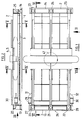
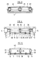
- the sieving machine shown in the drawing has a lower sieve frame designed as a fixed frame 1 and an upper sieve frame arranged as a swing frame 2 at a distance above the fixed frame 1, an elastic sieve covering 3 being provided between the fixed frame 1 and the swing frame 2 and the swing frame 2 is to be set in vibration and held by means of vibrating drives 4, 5.
- the fixed frame 1 is arranged immovably on a foundation 6, 7.
- the fixed frame 1 consists in the longitudinal direction of a left outer profile 8 and a right outer profile 9 with respect to the relations, for example according to FIG. 4.
- a left inner profile 11 and a right inner profile 12 are provided approximately in the middle between the central longitudinal axis 10 of the fixed frame 1 and the two outer profiles 8, 9 such that the distances between the left outer profile 8 and the left inner profile 11 and between the left inner profile 11 and the central longitudinal axis 10 and between the central longitudinal axis 10 and the right inner profile 12 and between the right inner profile 12 and the right outer profile 9 are the same.
- the fixed frame 1 has a lower cross bar 13 and an upper cross bar 14, with further cross bars 15, 16, 17, 18, 19 being provided between the two cross bars 13, 14 at certain equal distances from one another.
- three springs 20, 21, 22 are provided on the lower crossbeam 13, on which the swing frame 2 is resiliently mounted.
- three springs 23, 24, 25 are provided on the upper cross bar 14, on which the swing frame 2 is resiliently mounted at the upper end.
- bearing blocks 27, 28 are provided, on which two springs 29, 30 lying in the plane of the oscillating frame 2 are supported, which are supported against two bearing blocks 31, 32 fastened to the oscillating frame 2, through which the oscillating frame 2 is elastically supported in the direction of its plane.
- the swing frame 2 has a left longitudinal profile 33 and a right longitudinal profile 34, between which a middle profile 36 is provided in the middle on the central longitudinal axis 35 of the swing frame 2.
- the distances between the left longitudinal profile 33 and the central profile 36 and between the central profile 36 and the right longitudinal profile 34 are the same.
- the left outer profile 33 has a left bracket 37, just as the right outer profile 34 has a right bracket 38 and the middle profile 36 has a middle bracket 39.
- the fixed frame 1 and the swing frame 2 are arranged at a certain distance above one another, the distance being chosen so that the left inner profile 11 and the right inner profile 12 of the fixed frame 1 and the holders 37, 38, 39 of the swing frame 2 form a common plane, in which the elastic screen covering 3 is clamped.
- a left oscillating drive 4 is provided to the left of the oscillating frame 2 and a right oscillating drive 5 is provided on the opposite side of the oscillating frame 2.
- the oscillating drives 4, 5 are designed as balancing mass drives in such a way that the inner ring of a pillow block bearing is fixedly arranged on a journal.
- An eccentric mass is arranged on the outer ring of the pillow block bearing, which is sealed against the journal by a labyrinth bearing.
- the center of gravity of the balancing mass drive is as deep as possible placed so that its height deviates only slightly from the center of gravity of the longitudinal profile of the swing frame so that no swinging or wobbling movements of the swing frame can occur.
- the two drive shafts of the balancing mass drives are connected to each other via a chain drive, so that exactly synchronous operation is guaranteed.
- the drive pin of the one balancing mass drive is connected via a V-belt, for example a flat V-belt, to a motor arranged on one side outside of the oscillating frame, while the other drive pin is likewise connected via a V-belt to a motor arranged on the other side outside of the oscillating frame.
- the V-belts between the two motors and the two drive pins may have a certain amount of slip, but not the chain drive between the two drive pins.
- the oscillating drives 4, 5 are firmly connected to one another via a cross member 40.
- a cover 41 is provided above the swing frame 2.
- the screening machine is in the working position, that is to say at an angle of 20 °.
- the fixed frame 1 is mounted in an angularly variable manner by means of bearing blocks 42 on lower supports 43, while the upper end 44 of the screening machine is also mounted in an angle-changing manner by means of upper bearing blocks 45 on upper supports 46.
- the vibratory drives 4, 5 designed as eccentric drives rotate exactly synchronously, that is to say with exactly the same speed and exactly the same number of vibrations.
- the swing frame 2 leads in circular movement lying on its plane plane on the circular movement line 47. If the oscillating drives 4, 5 are not located in the center of gravity of the oscillating frame 2 but outside the center of gravity, the oscillating frame 2 does not describe a circular oscillating movement but an elliptical oscillating movement not shown in the drawing. This will only be useful in exceptional cases, while the circular vibration is normally aimed for.
- the holders 37, 38, 39 of the swing frame 2 move with respect to the profiles 8, 9, 11, 12 of the fixed frame 1 from a left outer position to a right outer position and back again to one left outside position and so on.
- the swing frame 2 assumes its left outer position.
- the first and third webs 48, 49 of the screen covering 3 are pulled tight from the left, while the webs arranged between them, namely the second and fourth webs 50, 51 of the screen covering 3, hang loosely from the left.
Landscapes
- Combined Means For Separation Of Solids (AREA)
Priority Applications (1)
| Application Number | Priority Date | Filing Date | Title |
|---|---|---|---|
| EP92110586A EP0576694A1 (fr) | 1992-06-29 | 1992-06-29 | Machine à tamiser |
Applications Claiming Priority (1)
| Application Number | Priority Date | Filing Date | Title |
|---|---|---|---|
| EP92110586A EP0576694A1 (fr) | 1992-06-29 | 1992-06-29 | Machine à tamiser |
Publications (1)
| Publication Number | Publication Date |
|---|---|
| EP0576694A1 true EP0576694A1 (fr) | 1994-01-05 |
Family
ID=8209741
Family Applications (1)
| Application Number | Title | Priority Date | Filing Date |
|---|---|---|---|
| EP92110586A Withdrawn EP0576694A1 (fr) | 1992-06-29 | 1992-06-29 | Machine à tamiser |
Country Status (1)
| Country | Link |
|---|---|
| EP (1) | EP0576694A1 (fr) |
Cited By (1)
| Publication number | Priority date | Publication date | Assignee | Title |
|---|---|---|---|---|
| DE102016011816A1 (de) | 2016-10-05 | 2018-04-05 | Hein, Lehmann Gmbh | Spannwellensiebmaschine mit optimierter Transportleistung |
Citations (5)
| Publication number | Priority date | Publication date | Assignee | Title |
|---|---|---|---|---|
| DE1204920B (de) * | 1963-01-05 | 1965-11-11 | Albert Wehner | Sieb- oder Foerdermaschine |
| DE2158128A1 (de) * | 1971-11-24 | 1973-05-30 | Albert Wehner | Siebrost |
| EP0206164A2 (fr) * | 1985-06-18 | 1986-12-30 | Hein, Lehmann Aktiengesellschaft | Machine à tamiser avec fond de tamis fixé à des éléments transversaux |
| DE8816250U1 (de) * | 1988-01-14 | 1989-03-02 | Hein, Lehmann AG, 4000 Düsseldorf | Spannwell-Siebmaschine |
| EP0405477A1 (fr) * | 1989-06-29 | 1991-01-02 | Johannes Dipl.-Ing. Brüderlein | Appareil de tamisage |
-
1992
- 1992-06-29 EP EP92110586A patent/EP0576694A1/fr not_active Withdrawn
Patent Citations (5)
| Publication number | Priority date | Publication date | Assignee | Title |
|---|---|---|---|---|
| DE1204920B (de) * | 1963-01-05 | 1965-11-11 | Albert Wehner | Sieb- oder Foerdermaschine |
| DE2158128A1 (de) * | 1971-11-24 | 1973-05-30 | Albert Wehner | Siebrost |
| EP0206164A2 (fr) * | 1985-06-18 | 1986-12-30 | Hein, Lehmann Aktiengesellschaft | Machine à tamiser avec fond de tamis fixé à des éléments transversaux |
| DE8816250U1 (de) * | 1988-01-14 | 1989-03-02 | Hein, Lehmann AG, 4000 Düsseldorf | Spannwell-Siebmaschine |
| EP0405477A1 (fr) * | 1989-06-29 | 1991-01-02 | Johannes Dipl.-Ing. Brüderlein | Appareil de tamisage |
Cited By (1)
| Publication number | Priority date | Publication date | Assignee | Title |
|---|---|---|---|---|
| DE102016011816A1 (de) | 2016-10-05 | 2018-04-05 | Hein, Lehmann Gmbh | Spannwellensiebmaschine mit optimierter Transportleistung |
Similar Documents
| Publication | Publication Date | Title |
|---|---|---|
| DE3402861C2 (fr) | ||
| EP0405477B1 (fr) | Appareil de tamisage | |
| DE1204920B (de) | Sieb- oder Foerdermaschine | |
| DE3524895C1 (de) | Siebmaschine | |
| EP1142651B1 (fr) | Dispositif de tamisage | |
| DE3139279A1 (de) | Schwingmaschine zum sieben und/oder foerdern, insbesondere einmassen-freischwinger-maschine | |
| DE3512215A1 (de) | Siebmaschine mit einem flexiblen siebbelag | |
| DE2158128A1 (de) | Siebrost | |
| EP0350830B1 (fr) | Appareil cribleur | |
| EP1228814B1 (fr) | Dispositif de tamisage | |
| EP4115993B1 (fr) | Dispositif crible, en particulier dispositif crible à effet trampoline | |
| EP0218575A2 (fr) | Dispositif de tamisage | |
| EP0576694A1 (fr) | Machine à tamiser | |
| DE2425923B2 (de) | Verfahren zur Abtrennung von Kaliumkationen von Natriumkationen | |
| EP2974803A1 (fr) | Crible dote de sections de criblage en forme de cassette | |
| AT400533B (de) | Spannwellensieb | |
| DE3226574C1 (de) | Siebmaschine | |
| DE1204504B (de) | Siebvorrichtung | |
| DE2425953C3 (de) | Niedrig bauende Siebmaschine | |
| DE828531C (de) | Siebboden | |
| DE3821689C1 (en) | Screening machine | |
| DE2135323A1 (de) | Schwingsieb, insbesondere schwingsieb fuer die feinabsiebung | |
| DE3330196C1 (de) | Siebmaschine | |
| DE4016877C2 (fr) | ||
| DE544880C (de) | Ortsfeste Siebanlage mit zwei gegenlaeufig bewegten ausgeglichenen Sieben |
Legal Events
| Date | Code | Title | Description |
|---|---|---|---|
| PUAI | Public reference made under article 153(3) epc to a published international application that has entered the european phase |
Free format text: ORIGINAL CODE: 0009012 |
|
| AK | Designated contracting states |
Kind code of ref document: A1 Designated state(s): AT BE CH DE DK FR LI NL |
|
| 17P | Request for examination filed |
Effective date: 19940630 |
|
| 17Q | First examination report despatched |
Effective date: 19960419 |
|
| STAA | Information on the status of an ep patent application or granted ep patent |
Free format text: STATUS: THE APPLICATION IS DEEMED TO BE WITHDRAWN |
|
| 18D | Application deemed to be withdrawn |
Effective date: 19960830 |