EP0576961A2 - Détection automatique du fond et du premier plan dans des images radiographiques numériques - Google Patents
Détection automatique du fond et du premier plan dans des images radiographiques numériques Download PDFInfo
- Publication number
- EP0576961A2 EP0576961A2 EP93109907A EP93109907A EP0576961A2 EP 0576961 A2 EP0576961 A2 EP 0576961A2 EP 93109907 A EP93109907 A EP 93109907A EP 93109907 A EP93109907 A EP 93109907A EP 0576961 A2 EP0576961 A2 EP 0576961A2
- Authority
- EP
- European Patent Office
- Prior art keywords
- foreground
- image
- background
- edge
- homogeneous
- Prior art date
- Legal status (The legal status is an assumption and is not a legal conclusion. Google has not performed a legal analysis and makes no representation as to the accuracy of the status listed.)
- Granted
Links
Images






Classifications
-
- G—PHYSICS
- G06—COMPUTING OR CALCULATING; COUNTING
- G06T—IMAGE DATA PROCESSING OR GENERATION, IN GENERAL
- G06T7/00—Image analysis
- G06T7/0002—Inspection of images, e.g. flaw detection
- G06T7/0012—Biomedical image inspection
-
- G—PHYSICS
- G06—COMPUTING OR CALCULATING; COUNTING
- G06T—IMAGE DATA PROCESSING OR GENERATION, IN GENERAL
- G06T7/00—Image analysis
- G06T7/10—Segmentation; Edge detection
- G06T7/11—Region-based segmentation
-
- G—PHYSICS
- G06—COMPUTING OR CALCULATING; COUNTING
- G06T—IMAGE DATA PROCESSING OR GENERATION, IN GENERAL
- G06T7/00—Image analysis
- G06T7/10—Segmentation; Edge detection
- G06T7/187—Segmentation; Edge detection involving region growing; involving region merging; involving connected component labelling
-
- G—PHYSICS
- G06—COMPUTING OR CALCULATING; COUNTING
- G06T—IMAGE DATA PROCESSING OR GENERATION, IN GENERAL
- G06T7/00—Image analysis
- G06T7/10—Segmentation; Edge detection
- G06T7/194—Segmentation; Edge detection involving foreground-background segmentation
-
- G—PHYSICS
- G06—COMPUTING OR CALCULATING; COUNTING
- G06T—IMAGE DATA PROCESSING OR GENERATION, IN GENERAL
- G06T2207/00—Indexing scheme for image analysis or image enhancement
- G06T2207/10—Image acquisition modality
- G06T2207/10116—X-ray image
-
- G—PHYSICS
- G06—COMPUTING OR CALCULATING; COUNTING
- G06T—IMAGE DATA PROCESSING OR GENERATION, IN GENERAL
- G06T2207/00—Indexing scheme for image analysis or image enhancement
- G06T2207/30—Subject of image; Context of image processing
- G06T2207/30004—Biomedical image processing
Definitions
- the present invention relates in general to digital image processing, and, more particularly, to a method for automatically separating (segmenting) the desired regions in a digital radiographic image (that is, the body part being imaged) from the undesired regions (areas around the body part that have received unattenuated radiation or have received very little radiation due to the use of beam limiting devices).
- LUT look-up table
- edge enhancement techniques can be used to increase the visual contrast of edges, and therefore the conspicuity of certain kinds of structures in an image.
- histogram-based tone-scale transformation is a simple and effective way of adjusting the contrast of an image.
- the histogram is a global characteristic of the image, and therefore does not distinguish between the desired or important regions of the image (for example, the body part or portion being imaged) and the undesired or unimportant regions of the image (for example, regions of direct x-ray background or areas of very low exposure behind collimator blades used to restrict the size of the irradiation field).
- a tone-scale transformation based on such a histogram will be suboptimum if it is unduly influenced by the unimportant regions of the image.
- the word “background” will be used to denote the direct x-ray background, that is, the region around the body part being imaged that has received unattenuated x-rays.
- the word “foreground” will be used to denote highly (x-ray) absorbing structures, like collimator blades, used to define the size and shape of the irradiation field.
- a digital radiograph consists of three regions: the body part being imaged (the object), the background, and the foreground.
- Histogram-based methods for detecting foreground and/or background usually depend on the detection and recognition of peaks in the histogram (see Sezan and others., IEEE Trans. Med. Imaging, vol. 8, p. 154, 1989).
- US-A-4,731,863 teaches a technique for finding gray level thresholds between anatomical structures and image regions based on zero-crossings of a peak detection function derived from application of smoothing and differencing operators to the image histogram. This method produces a series of peaks by analyzing the histogram at several different signal resolutions.
- One problem with this method is that the peaks need to be interpreted for each exam type and exposure technique.
- a low-signal peak could correspond to foreground, but it could also correspond to a body portion if no foreground is present in the image.
- a high-signal peak may be the image background, or it may be a high-signal body portion. Thus, some additional information may be needed to make the method robust.
- European Patent Application 288,042 published October 26, 1988, inventors Tanaka and others. proposes a foreground and background finding method using the image histogram.
- the histogram is again divided into a number of sections by an automatic thresholding procedure.
- a statistical analysis discriminate analysis
- This method is less prone to variations in exam type and input modality because this information is incorporated into the decision process.
- the use of fixed thresholds still poses problems if there is nonuniformity in either the foreground or background.
- histogram-based methods work best when the peaks in the histogram corresponding to foreground and background are far enough away from the peak(s) corresponding to the body part of interest that they can be identified as separate. If the peaks overlap, which can occur if the background or foreground are nonuniform across the image, or if scatter behind the collimators causes the signal level in that area to come close to the highly x-ray absorbing structures in the body, then it becomes more difficult to separate foreground/background regions in the histogram with a single threshold.
- a more effective way of detecting foreground and background is to include spatial information about the image in the analysis, in addition to the intensity information provided by the histogram.
- Several methods have been described for doing this.
- This method is claimed to provide a more accurate measure of the field than a simple histogram method.
- it still requires an a priori knowledge that a collimator or field stop was in fact used to define the irradiation field, otherwise low-signal portions of the image inside the body part may be clipped by the intensity thresholding that defines the boundary.
- image pixels inside the body part have a signal value comparable to or lower than those underneath the collimator region (as when there is significant x-ray scatter), the edge of the irradiation field may not even be found with this method.
- a second problem has already been mentioned above, namely, that the method assumes that the signal values inside the irradiation field are always larger than those immediately outside it, which is not always the case when scatter is present.
- a third problem is that if subdivision recording has been used, the method may not find all of the necessary edges to define each irradiation field within the image.
- the use of multiple linear or nonlinear fits on multiple lines across the image is an inefficient, time-consuming way to find the field boundaries.
- a preprocessing stage can be used to identify the use of subdivision recording and also the format of the image (2-on-1, 4-on-1, and so forth.).
- US-A-4,829,181 teaches a method of recognizing a subdivision pattern in a storage phosphor system using differentiation to detect prospective edge points, followed by a colinearity test to see if the edge points lie on straight lines. If the edge points lie on straight lines, subdivision recording is judged to be present.
- a limitation of this method is that it can detect only rectilinear patterns, that is, patterns with essentially horizontal or vertical linear separations.
- US-A-4,962,539 discloses a method that uses a set of binary, stored masks representing typical subdivision recording patterns.
- the input digital image is converted into a binary image by thresholding, and the resulting binary image is statistically compared with each of the masks in the stored set.
- the stored mask with the highest degree of matching is judged to be the recording pattern on the input image. While this method can handle a wider variety of patterns than the one above, it is still limited to the stored library of patterns for matching. Any irregular patterns not included in the library may not have a high degree of matching, and may therefore be chosen incorrectly. Furthermore, the statistical matching can be complex and time consuming.
- a problem to be solved in the prior art is to provide a technique for automatically separating the desired regions in a digital radiographic image from the undesired background and foreground regions.
- this problem is solved by providing an automatic digital image processing method for detecting and distinguishing in digital radiographic images the desired region, such as the object region, from the undesired regions, such as both the regions of direct x-ray exposure around the body part being imaged ("background") and the regions in which beam-limiting devices have been used to restrict the size of irradiation field ("foreground").
- the foreground and background detection method consists of five steps: edge detection, block generation, block classification, block refinement, and bit map generation.
- edge detection the edge content of the image is analyzed.
- the local edge content is one indicator of the level of detail or "busyness" in various parts of the image, and, therefore, an indicator of whether these parts are more likely to belong to the foreground/background region or to the object region.
- the image is broken into a set of nonoverlapping, contiguous blocks of pixels. Further analysis of the image and the classification into foreground, background, and object take place on a block-by-block basis.
- the third method step is block classification.
- each block can have, depending on whether the block is basically homogeneous (relatively low edge density) or nonhomogeneous (relatively high edge density), and on what it contains (foreground pixels, background pixels, object pixels, mixtures of foreground pixels with background pixels, or mixtures of foreground and/or background pixels with object pixels).
- the information about edge content along with similar information from neighboring blocks is fed into a syntactic reasoning section that uses a set of clinically and empirically determined decision rules to classify each block of the image into one of two categories: foreground/background or object.
- a refinement step evaluates the fine structure inside each block and reclassifies portions of the block into the above-mentioned two categories. This ensures that the edge pixels of the body part being imaged are not misclassified.
- the block classification arrived at in the previous step is then used to create a two-valued (binary) image that functions as a template for any further image processing to be done on the image. For example, if a histogram of the image is required, only those pixels with the correct value in the binary image are included in the calculation. If edge enhancement is being performed, pixels in the foreground/background blocks are not included in the calculation of enhancement parameters. In this way, only the relevant information in the image is included in subsequent image processing of the image, leading to images with high quality and high diagnostic utility.
- Another object of the present invention is to detect a plurality of irradiation subregions on a single image.
- the detection method consists of five steps: edge detection, block generation, block classification, region growing, and bit map generation.
- the first two stages are the same as those of the aforementioned foreground/background detection method.
- a block is simply categorized into two states, depending on whether the block is homogeneous (relatively low edge density) or nonhomogeneous (relatively high edge density).
- a region-growing process starting from the homogeneous corner blocks of the image, is then used to detect the plurality of irradiation subregions.
- a two-valued (binary) image is generated to function as a template such that the aforementioned foreground/background detection method can be applied to each irradiation subregion.
- An advantageous effect of the invention is to automatically separate the desired object regions and digital radiographic image from the undesired background and foreground regions.
- FIG. 1a illustrates a typical system 10 in which the present invention could be practiced.
- the system consists of an image acquisition section (scanner) 12 in which the digital radiographic image signals 14 are obtained, a digital image signal processing section 16 in which the digital image signal data are manipulated with image processing algorithms intended to improve the appearance, diagnostic utility, and other properties of the image, and an image display section 18 in which the final processed output image signal 20 is made viewable.
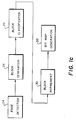
- the method of the present invention would be inserted as a digital image segmentation section 22 into this imaging chain between the acquisition section 12 and the image processing section 16, as shown in FIG. 1b.
- the actual implementation of the present invention does not need to be separated from these two sections. It could, of course, reside directly in the acquisition section 12 or in the image processing section 16. In this way, the separation or segmentation of the image signal 14 into relevant and irrelevant or desired and undesired regions will occur before any other image processing takes place.
- the digital radiographic image signals to be processed with this invention can be acquired in a variety of different systems, for example, from storage phosphor (computed radiography) systems, film digitizer systems, image intensifier systems, and so forth.
- CT computed tomography
- MRI magnetic resonance imaging
- film writers either laser printers or cathode ray tube (CRT) printers
- CRT soft displays are examples of display devices.
- the digital image segmentation method of the present invention includes the following steps, edge detection 24, block generation 26, block classification 28, block refinement 30 and bit map generation 32.
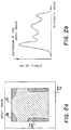
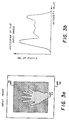
- FIG.2a shows a chest image signal containing foreground 34, background 36, and object regions 38 as defined in the present invention.
- the object region 38 in this case is the region inside the body part being imaged, that is, the region bounded on the left and right of the object by the skin line, and on the top and bottom of the object by the edge of a beam limiting device (collimator).
- the histogram of this digital image signal is shown in FIG. 2b as a graphical representation of the number of pixels at each pixel intensity value.
- the first step in the method of the present invention is to detect and characterize the edges in the image signal, and, in particular, to find the density of edges in various parts of the image signal.
- an edge detection step is used.
- edge detection algorithms are known in the literature (see, for example, A. Rosenfeld, A.C. Kak, Digital Picture Processing , Academic Press, 1982), many of which may be suitable for use as edge detectors in the present invention.
- a morphological edge detector has been chosen because of its low sensitivity to noise, and its ability to yield an edge strength measure that is proportional to the contrast between the foreground/background and the object and is independent of the edge position and orientation.
- a brief discussion of morphological techniques is given in Appendix A.
- edge detection step it is preferable to operate the edge detection step on a smoothed version of the input image signal, rather than the original image signal. This is because the edge detection step can be sensitive to noise and may therefore create edge pixels in regions of the image where there really are no edges.
- a spatial filtering operation is used. For example, a local average of the eight nearest neighbors could be used to produce the smoothed image signal, although other methods are available.
- the expression for the edge signal produced with the morphological edge detector of the preferred embodiment of this invention is given by: where is the smoothed input image, and B is the structuring element of the morphological operation.
- the size and shape of the structuring element must be matched to the size of the image and the structures the edge detector is intended to find.
- Smaller structuring elements are capable of locating smaller features and are more computationally efficient than larger structuring elements, which are sensitive to coarser structures in the image.
- the desired structures are reasonably large (that is, containing relatively many pixels) in the smoothed input image signal, , it is often easier and more efficient to scale down the input image signal by decimation (subsampling) or averaging than to scale up the structuring element to match the size of the details of interest.
- the structuring element can be made separable, that is, the two-dimensional structure B(x,y) can be represented as a product of two one-dimensional windows
- the computational effort of the edge detection stage can be reduced considerably, and the one-dimensional images produced by the separable structuring element, denoted by g x and g y , can be recombined into a single edge signal image, for example, by quadrature:
- the output of the edge detection step is an edge strength map signal, g(x,y), containing high-amplitude pixels in areas of strong edges and low-amplitude pixels in areas of weak or no edge.
- This map image signal must be thresholded in order to include only the most significant edges needed to distinguish object and foreground/background regions in the image signal.
- the choice of this (global) threshold can depend on factors like the exam type, the typical noise content of the input modality, and the amount of smoothing used in the preprocessing stage. Pixels in the edge strength image, g(x,y), with values greater than the threshold T e are considered to be edge pixels. The remaining pixels are considered to be non-edge pixels.
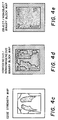
- a binary edge image, E(x,y) is produced from the edge strength map by thresholding: This is shown in FIG. 4c.
- the edge strength map, g(x,y) can be compared to several thresholds calculated in different ways.
- the threshold is adjusted to match the actual dynamic range of the edge signals.
- the proportionality constant, ⁇ 1 must be determined experimentally for a variety of exam types.
- a threshold can be found by requiring that some fixed proportion, ⁇ 2, of the detected edge pixels be retained in the edge strength image.
- the proportionality constant, ⁇ 2 is empirically determined based on characteristics of the image class. Other methods of threshold selection are also possible.
- the method is to automatically choose a threshold that maximizes the sum of the gradient values, g(x,y), taken over all pixels with a value equal to the threshold: Since this method essentially involves the product of a threshold value and the number of pixels at that value, it is especially useful in cases when there are strong edges involving many pixels, as in the case of collimator blade edges delimiting an irradiation field.
- the next step of the preferred method of the invention is to divide the image signal into a set of nonoverlapping, contiguous blocks of pixels for further analysis.
- the size of the pixel blocks depends on the size of the image.
- the blocks should be large enough to be able to calculate local statistical properties (for example, mean and standard deviation), but small enough to resolve the structures necessary for accurately segmenting the foreground and background.
- local statistical properties for example, mean and standard deviation
- each block can have ten possible states, depending on its degree of homogeneity and what it contains.
- the ten possible states of each block are:
- the next step is to classify the blocks.
- the first classification is into homogeneous and nonhomogeneous blocks.
- a block is defined as homogeneous if it has no or very few edge pixels, and has a low variance. Any block that does not meet these two criteria is considered nonhomogeneous.
- the edge density, m d , for a block can be defined as the ratio of the number of edge pixels in a block (after thresholding) to the total number of pixels in the block. If the image size is N x pixels/line and N y lines, and the block size is S x by S y , then the edge density for BLOCK(p,q) is given by: where The variance of BLOCK(p,q) can be calculated by standard statistical methods as: where l and r are the left-most and right-most nonzero gray levels in the local histogram h of BLOCK(p,q) and ⁇ is the mean gray level of the block.
- each block is subjected to the aforesaid two tests for edge density and variance. These tests involve a threshold comparison for each block.
- the edge density threshold for each block, T d can, for example, be chosen as some fixed fraction of the edge density of the entire image, that is, where ⁇ is the fixed fraction, which can be determined empirically.
- the threshold for the variance, T v can be determined by experiments.
- the blocks that have been classified as homogeneous can be homogeneous foreground or background as well as homogeneous object regions (for example, the subdiaphragmatic region in a chest image can sometimes be homogeneous). Further tests will be required to distinguish the homogeneous object regions from the homogeneous foreground/background regions.
- the blocks classified as nonhomogeneous can consist of nonhomogeneous foreground, background, and/or object, as well as combinations of the three.
- syntactic reasoning and refinement are used.
- the methods proposed in the prior art described above generally use low-level image processing techniques similar to those described so far for the present invention, for example, the detection of edges, the characteristics of local or global histograms, and global thresholding.
- higher level image processing techniques be used to refine and modify the results obtained with the lower level techniques.
- a high-level processing technique called syntactic reasoning is first used to analyze and improve the results of the low-level stage.
- the parameter ⁇ can be determined empirically.
- FIG. 6a shows a diagram for the process of refining the nonhomogeneous (mixed) boundary blocks.
- FIG. 6b shows the histogram of the block [p,q], as well as the high and low thresholds computed from the 8-neighboring blocks of the block [p,q]. Those pixels in the block [p,q] with gray levels greater than T L (p,q) and less than T H (p,q) are considered to be object pixels.
- the parameters of the method which need to be determined through experimentation are given in Table 1 for four different exam types, chest, extremity, skull, and abdomen. These were determined by using the method on images acquired from storage phosphor systems and scanned film systems. It has been observed by the inventors that the typical values for ⁇ , T V , ⁇ 5, and ⁇ are 0.1, 8.5, 0.25, and 1.0, respectively.
- the other parameters that are employed in the syntactic reasoning depend on the exam type. In the case of the storage phosphor images, the original images were acquired at a resolution of 2048 pixels/line and 2500 lines and 12 bits/pixel.
- the image was subsampled by a factor of 9 in both directions, resulting in an image 227 pixels by 277 pixels in size.
- the block size was selected to be 10 pixels by 10 pixels, which is about the order of 1/20th of the linear dimension of the subsampled image.
- a 3 x 3 structuring element which can be represented as a product of two one-dimensional windows (that is, 3 x 1 and 1 x 3 windows), was used in the aforementioned morphological edge detector.
- the method was applied to this image using a SUN 4/110 workstation with the algorithm implemented in software.
- the output of the method was a 1-bit image with 0 indicating the foreground/background regions and 1 indicating the object regions. This result was achieved in approximately 10 seconds. Hardware implementation is obviously also possible, with a significant reduction of processing time.
- the image size of the subsampled image chosen for the preferred embodiment of the present invention was based on a series of tests with image sizes ranging from full resolution (2048 x 2500) to 64 x 78. There was very little influence on the quality of the result with image size until the smallest sizes were reached (subsampling factors greater than approximately 16). Thus, efficient operation can be achieved even though the present invention involves higher level syntactic analysis in order to do the segmentation accurately.
- FIG. 7a Another mode of the present invention is to detect a plurality of irradiation subregions on a single image.
- the detection method consists of edge detection, block generation, block classification, region growing, and bit map generation.
- a morphological edge detector as described in the aforementioned foreground/background detection method is used. This is shown in FIG. 7b.
- An image is then divided into a set of nonoverlapping, contiguous blocks, and each block is classified as homogeneous or nonhomogeneous according to Eq. (10).
- the resulting image, denoted by H is shown in FIG. 7c.
- the complement of H denoted by H c , is created. This is shown in FIG. 7d.
- the region-growing stage is an iterative process which begins by setting the homogeneous corner blocks as the initial seeds. This is shown in FIG. 7e. In each iteration, the seeds are expanded to their 4-neighbors (that is, the right, left, top, and bottom blocks), and the intermediate result is intersected with H c , yielding a new set of seeds to be grown in the next iteration. The process repeats until there is no change in any two successive iterations.
- FIGS. 7f through 7k show the seeds after 2, 3, 4, 5, 10, and 15 iterations, respectively. The converged result is shown in FIG. 71 where the seeds image does not change even if the iteration continues.
- a bit map of a plurality of irradiation subregions can be obtained by complementing the converged seeds image, which is shown in FIG. 7m.
- the aforementioned foreground/background detection method can then be applied to each subregion of the image, leading to images with high quality and high diagnostic utility in each subregion.
Landscapes
- Engineering & Computer Science (AREA)
- Computer Vision & Pattern Recognition (AREA)
- Physics & Mathematics (AREA)
- General Physics & Mathematics (AREA)
- Theoretical Computer Science (AREA)
- General Health & Medical Sciences (AREA)
- Health & Medical Sciences (AREA)
- Medical Informatics (AREA)
- Nuclear Medicine, Radiotherapy & Molecular Imaging (AREA)
- Radiology & Medical Imaging (AREA)
- Quality & Reliability (AREA)
- Apparatus For Radiation Diagnosis (AREA)
- Image Analysis (AREA)
- Image Processing (AREA)
- Length-Measuring Devices Using Wave Or Particle Radiation (AREA)
Applications Claiming Priority (2)
| Application Number | Priority Date | Filing Date | Title |
|---|---|---|---|
| US07/906,191 US5268967A (en) | 1992-06-29 | 1992-06-29 | Method for automatic foreground and background detection in digital radiographic images |
| US906191 | 1992-06-29 |
Publications (3)
| Publication Number | Publication Date |
|---|---|
| EP0576961A2 true EP0576961A2 (fr) | 1994-01-05 |
| EP0576961A3 EP0576961A3 (en) | 1994-05-11 |
| EP0576961B1 EP0576961B1 (fr) | 2001-12-05 |
Family
ID=25422077
Family Applications (1)
| Application Number | Title | Priority Date | Filing Date |
|---|---|---|---|
| EP93109907A Expired - Lifetime EP0576961B1 (fr) | 1992-06-29 | 1993-06-22 | Détection automatique du fond et du premier plan dans des images radiographiques numériques |
Country Status (4)
| Country | Link |
|---|---|
| US (1) | US5268967A (fr) |
| EP (1) | EP0576961B1 (fr) |
| JP (1) | JPH06348818A (fr) |
| DE (1) | DE69331251T2 (fr) |
Cited By (9)
| Publication number | Priority date | Publication date | Assignee | Title |
|---|---|---|---|---|
| EP0826960A1 (fr) * | 1996-08-29 | 1998-03-04 | Societe Nationale D'etude Et De Construction De Moteurs D'aviation "Snecma" | Procédé de détection automatique de défauts dans des pièces mécaniques à géométrie complexe |
| WO1998048381A1 (fr) * | 1997-04-18 | 1998-10-29 | At & T Corp. | Integration de reperes monoculaires pour ameliorer la perception de profondeur |
| DE19742152A1 (de) * | 1997-09-24 | 1999-03-25 | Siemens Ag | Bildsystem für eine medizinische Diagnostikeinrichtung und Verfahren zur gefensterten Darstellung von medizinischen Bildern |
| EP0863486A3 (fr) * | 1997-03-06 | 1999-07-14 | Xerox Corporation | Procédé et dispositif de détection automatique du bord d'un document utilisant un scanner |
| EP0824246A3 (fr) * | 1996-08-06 | 2002-06-19 | Xerox Corporation | Découpe d'image automatique |
| WO2006041548A1 (fr) * | 2004-10-06 | 2006-04-20 | Siemens Medical Solutions Usa, Inc. | Extraction de signal ultrasonore a partir d'images ultrasonores medicales |
| EP1089230A3 (fr) * | 1999-09-24 | 2008-06-11 | Nippon Telegraph and Telephone Corporation | Méthode et appareil de séparation de symbole graphique d'arrière-plan et d'objet d'avant-plan et méthode et appareil d'extraction d'un masque de segmentation |
| CN104424480A (zh) * | 2013-08-29 | 2015-03-18 | 亚德诺半导体集团 | 面部识别 |
| CN107507227A (zh) * | 2017-08-02 | 2017-12-22 | 太仓美宅姬娱乐传媒有限公司 | 一种应用于视频检测中的背景更新方法 |
Families Citing this family (143)
| Publication number | Priority date | Publication date | Assignee | Title |
|---|---|---|---|---|
| US5537485A (en) * | 1992-07-21 | 1996-07-16 | Arch Development Corporation | Method for computer-aided detection of clustered microcalcifications from digital mammograms |
| DE4326716B4 (de) * | 1992-08-04 | 2005-03-03 | Kabushiki Kaisha Topcon | Anordnung zur Verarbeitung eines ophthalmologischen Bildes |
| GB2270243B (en) * | 1992-08-26 | 1996-02-28 | Namco Ltd | Image synthesizing system |
| US5447153A (en) * | 1993-07-02 | 1995-09-05 | Eastman Kodak Company | Real-time window/leveling on a radiographic workstation |
| US5374932A (en) * | 1993-08-02 | 1994-12-20 | Massachusetts Institute Of Technology | Airport surface surveillance system |
| US5519618A (en) * | 1993-08-02 | 1996-05-21 | Massachusetts Institute Of Technology | Airport surface safety logic |
| US5452367A (en) * | 1993-11-29 | 1995-09-19 | Arch Development Corporation | Automated method and system for the segmentation of medical images |
| US5420971A (en) * | 1994-01-07 | 1995-05-30 | Panasonic Technologies, Inc. | Image edge finder which operates over multiple picture element ranges |
| US6268935B1 (en) * | 1994-04-15 | 2001-07-31 | Minolta Co., Ltd. | Image processor |
| US5570430A (en) * | 1994-05-31 | 1996-10-29 | University Of Washington | Method for determining the contour of an in vivo organ using multiple image frames of the organ |
| WO1996009604A1 (fr) * | 1994-09-20 | 1996-03-28 | Neopath, Inc. | Appareil d'identification automatique d'amas cellulaires dans un prelevement biologique |
| AU3629295A (en) * | 1994-09-20 | 1996-04-09 | Neopath, Inc. | Apparatus for automated identification of thick cell groupings on a biological specimen |
| US5757954A (en) * | 1994-09-20 | 1998-05-26 | Neopath, Inc. | Field prioritization apparatus and method |
| US5978497A (en) * | 1994-09-20 | 1999-11-02 | Neopath, Inc. | Apparatus for the identification of free-lying cells |
| US5588071A (en) * | 1994-10-26 | 1996-12-24 | Minnesota Mining And Manufacturing Company | Identifying an area of interest using histogram data arranged in predetermined sequence |
| JP3264932B2 (ja) * | 1995-01-31 | 2002-03-11 | ユナイテッド パーセル サービス オブ アメリカ インコーポレイテッド | テキストを含む画像における背景から前景を分離する方法及び装置 |
| DE69636911T2 (de) * | 1995-03-29 | 2007-11-22 | Fujifilm Corp. | Bildverarbeitungsverfahren und -Vorrichtung |
| EP0742536B1 (fr) * | 1995-05-11 | 2000-09-13 | Agfa-Gevaert N.V. | Procédé de reconnaissance de champs d'irradiation |
| US5812787A (en) * | 1995-06-30 | 1998-09-22 | Intel Corporation | Video coding scheme with foreground/background separation |
| JP3003561B2 (ja) * | 1995-09-25 | 2000-01-31 | 松下電器産業株式会社 | 階調変換方法及びその回路と画像表示方法及びその装置と画像信号変換装置 |
| US5862249A (en) * | 1995-12-01 | 1999-01-19 | Eastman Kodak Company | Automated method and system for determination of positional orientation of digital radiographic images |
| US5633511A (en) * | 1995-12-22 | 1997-05-27 | Eastman Kodak Company | Automatic tone scale adjustment using image activity measures |
| US5648660A (en) * | 1996-01-05 | 1997-07-15 | Sterling Diagnostic Imaging, Inc. | Method and apparatus for reducing noise in a radiation capture device |
| US5825909A (en) * | 1996-02-29 | 1998-10-20 | Eastman Kodak Company | Automated method and system for image segmentation in digital radiographic images |
| US5892840A (en) * | 1996-02-29 | 1999-04-06 | Eastman Kodak Company | Method and apparatus for irradiation field detection in digital radiographic images |
| US5757953A (en) * | 1996-02-29 | 1998-05-26 | Eastman Kodak Company | Automated method and system for region decomposition in digital radiographic images |
| US5889882A (en) * | 1996-03-21 | 1999-03-30 | Eastman Kodak Company | Detection of skin-line transition in digital medical imaging |
| US5606587A (en) * | 1996-03-21 | 1997-02-25 | Eastman Kodak Company | Determination of direct x-ray exposure regions in digital medical imaging |
| KR100242636B1 (ko) * | 1996-03-23 | 2000-02-01 | 윤종용 | 블록화효과 및 링잉노이즈 감소를 위한 신호적응후처리시스템 |
| US6078619A (en) * | 1996-09-12 | 2000-06-20 | University Of Bath | Object-oriented video system |
| US6175655B1 (en) | 1996-09-19 | 2001-01-16 | Integrated Medical Systems, Inc. | Medical imaging system for displaying, manipulating and analyzing three-dimensional images |
| US5900732A (en) * | 1996-11-04 | 1999-05-04 | Mayo Foundation For Medical Education And Research | Automatic windowing method for MR images |
| US5901240A (en) * | 1996-12-12 | 1999-05-04 | Eastman Kodak Company | Method for detecting the collimation field in a digital radiography |
| US5990956A (en) * | 1996-12-30 | 1999-11-23 | Daewoo Electronics, Inc. | Method and apparatus for padding a video signal for shape adaptive transformation |
| DE69711027T2 (de) * | 1997-06-05 | 2002-10-17 | Agfa-Gevaert, Mortsel | Verfahren zur Segmentierung eines Strahlungsbildes in direktes Belichtungsgebiet und diagnostisch relevantes Gebiet |
| US6353674B1 (en) * | 1997-06-05 | 2002-03-05 | Agfa-Gevaert | Method of segmenting a radiation image into direct exposure area and diagnostically relevant area |
| US5930327A (en) * | 1997-06-23 | 1999-07-27 | Trex Medical Corporation | X-ray image processing |
| US5903660A (en) * | 1997-07-16 | 1999-05-11 | The Regents Of The University Of California | Automatic background recognition and removal (ABRR) in projection digital radiographic images (PDRI) |
| US6246784B1 (en) | 1997-08-19 | 2001-06-12 | The United States Of America As Represented By The Department Of Health And Human Services | Method for segmenting medical images and detecting surface anomalies in anatomical structures |
| US7308126B2 (en) * | 1997-08-28 | 2007-12-11 | Icad, Inc. | Use of computer-aided detection system outputs in clinical practice |
| US6970587B1 (en) | 1997-08-28 | 2005-11-29 | Icad, Inc. | Use of computer-aided detection system outputs in clinical practice |
| US5999639A (en) | 1997-09-04 | 1999-12-07 | Qualia Computing, Inc. | Method and system for automated detection of clustered microcalcifications from digital mammograms |
| JP3114668B2 (ja) | 1997-10-03 | 2000-12-04 | 日本電気株式会社 | 物体検出・背景除去方法、装置およびプログラムを記録した記録媒体 |
| US6018590A (en) * | 1997-10-07 | 2000-01-25 | Eastman Kodak Company | Technique for finding the histogram region of interest based on landmark detection for improved tonescale reproduction of digital radiographic images |
| US5978443A (en) * | 1997-11-10 | 1999-11-02 | General Electric Company | Automated removal of background regions from radiographic images |
| US6317510B1 (en) * | 1997-12-19 | 2001-11-13 | Fuji Photo Film Co., Ltd. | Blackening processing method and apparatus |
| US6212291B1 (en) | 1998-01-29 | 2001-04-03 | Eastman Kodak Company | Method for recognizing multiple irradiation fields in digital radiography |
| US6208763B1 (en) * | 1998-04-14 | 2001-03-27 | General Electric Company | Method and apparatus for enhancing discrete pixel images |
| US6173083B1 (en) * | 1998-04-14 | 2001-01-09 | General Electric Company | Method and apparatus for analyzing image structures |
| US6996549B2 (en) | 1998-05-01 | 2006-02-07 | Health Discovery Corporation | Computer-aided image analysis |
| KR100367831B1 (ko) * | 1998-06-30 | 2003-01-10 | 주식회사 팬택앤큐리텔 | 영상의 색차신호 필터링 방법 및 장치 |
| JP4328399B2 (ja) * | 1998-08-31 | 2009-09-09 | キヤノン株式会社 | 画像処理装置、画像処理方法、及び記憶媒体 |
| US7013035B2 (en) * | 1998-09-25 | 2006-03-14 | Canon Kabushiki Kaisha | Image processing method for setting an extraction area, and apparatus and recording medium |
| DE69922317D1 (de) * | 1998-09-29 | 2005-01-05 | Koninkl Philips Electronics Nv | Bildverarbeitungsverfahren für medizinische Ultraschall-Abbildungen der Knochenstruktur, und ein Gerät für rechnerunterstützte Chirurgie |
| US6118892A (en) * | 1998-11-19 | 2000-09-12 | Direct Radiography Corp. | Method for automatic detection of region of interest for digital x-ray detectors using a filtered histogram |
| US6101238A (en) * | 1998-11-25 | 2000-08-08 | Siemens Corporate Research, Inc. | System for generating a compound x-ray image for diagnosis |
| US6249590B1 (en) | 1999-02-01 | 2001-06-19 | Eastman Kodak Company | Method for automatically locating image pattern in digital images |
| JP4101392B2 (ja) * | 1999-04-08 | 2008-06-18 | 富士フイルム株式会社 | 画像定量方法および装置 |
| US6801645B1 (en) | 1999-06-23 | 2004-10-05 | Icad, Inc. | Computer aided detection of masses and clustered microcalcifications with single and multiple input image context classification strategies |
| US6381351B1 (en) | 1999-11-24 | 2002-04-30 | Direct Radiography Corp. | Weighted inverse topography method for digital x-ray image data processing |
| US6674925B1 (en) * | 2000-02-08 | 2004-01-06 | University Of Washington | Morphological postprocessing for object tracking and segmentation |
| JP3631095B2 (ja) * | 2000-04-17 | 2005-03-23 | キヤノン株式会社 | 照射野領域抽出装置、放射線撮影装置、放射線画像用システム、照射野領域抽出方法、及びコンピュータ可読記憶媒体 |
| JP2001358957A (ja) * | 2000-06-09 | 2001-12-26 | Ricoh Co Ltd | 画像処理方法および画像処理装置および記録媒体 |
| US6587213B1 (en) * | 2000-11-15 | 2003-07-01 | The United States Of America As Represented By The Secretary Of The Army | Nondestruction coating adhesion evaluation using surface ultrasonic waves and wavelet analysis |
| KR100859381B1 (ko) * | 2001-06-15 | 2008-09-22 | 소니 가부시끼 가이샤 | 화상 처리 장치 및 방법 및 촬상 장치 |
| CN1213592C (zh) * | 2001-07-31 | 2005-08-03 | 佳能株式会社 | 采用自适应二值化的图象处理方法和设备 |
| DE10213284B4 (de) * | 2002-03-25 | 2007-11-08 | Siemens Ag | Verfahren zur Bilddarstellung in der medizinischen Bildgebung |
| US6941011B2 (en) * | 2002-06-27 | 2005-09-06 | Hewlett-Packard Development Company, Lp. | Method and system for image processing including mixed resolution, multi-channel color compression, transmission and decompression |
| US7260250B2 (en) * | 2002-09-30 | 2007-08-21 | The United States Of America As Represented By The Secretary Of The Department Of Health And Human Services | Computer-aided classification of anomalies in anatomical structures |
| DE10250781B4 (de) * | 2002-10-30 | 2007-07-26 | Orga Systems Gmbh | Verfahren und Vorrichtung zur automatischen Segmentierung eines Vordergrundobjektes in einem Bild |
| US20060104535A1 (en) * | 2002-12-05 | 2006-05-18 | Christiaan Varekamp | Method and apparatus for removing false edges from a segmented image |
| US20040161153A1 (en) * | 2003-02-18 | 2004-08-19 | Michael Lindenbaum | Context-based detection of structured defects in an image |
| US7218763B2 (en) * | 2003-02-27 | 2007-05-15 | Eastman Kodak Company | Method for automated window-level settings for magnetic resonance images |
| JP4237145B2 (ja) * | 2003-05-15 | 2009-03-11 | 富士通株式会社 | 生体情報検出装置 |
| US7627171B2 (en) * | 2003-07-03 | 2009-12-01 | Videoiq, Inc. | Methods and systems for detecting objects of interest in spatio-temporal signals |
| US7391895B2 (en) * | 2003-07-24 | 2008-06-24 | Carestream Health, Inc. | Method of segmenting a radiographic image into diagnostically relevant and diagnostically irrelevant regions |
| US20050129297A1 (en) * | 2003-12-15 | 2005-06-16 | Kamath Vidya P. | Classification of breast lesion method and system |
| US7623728B2 (en) * | 2004-03-24 | 2009-11-24 | General Electric Company | Method and product for processing digital images |
| KR100615362B1 (ko) * | 2004-06-04 | 2006-08-25 | 남상희 | 엑스레이 디텍터의 데이터 제어장치 및 방법 |
| US8391593B2 (en) * | 2004-06-09 | 2013-03-05 | Hewlett-Packard Development Company, L.P. | Image processing methods and systems |
| DE102004061507B4 (de) * | 2004-12-21 | 2007-04-12 | Siemens Ag | Verfahren zur Korrektur von Inhomogenitäten in einem Bild sowie bildgebende Vorrichtung dazu |
| DE102005010076A1 (de) * | 2005-03-04 | 2006-09-07 | Siemens Ag | Bildbearbeitungsverfahren für ein digitales medizinisches Untersuchungsbild und zugehörige Untersuchungseinrichtung |
| US9769354B2 (en) | 2005-03-24 | 2017-09-19 | Kofax, Inc. | Systems and methods of processing scanned data |
| US9137417B2 (en) | 2005-03-24 | 2015-09-15 | Kofax, Inc. | Systems and methods for processing video data |
| US7991242B2 (en) | 2005-05-11 | 2011-08-02 | Optosecurity Inc. | Apparatus, method and system for screening receptacles and persons, having image distortion correction functionality |
| EP1886257A1 (fr) | 2005-05-11 | 2008-02-13 | Optosecurity Inc. | Procede et systeme d'inspection de bagages, de conteneurs de fret ou de personnes |
| US7711165B2 (en) * | 2005-07-28 | 2010-05-04 | Siemens Medical Solutions Usa, Inc. | System and method for coronary artery segmentation of cardiac CT volumes |
| US20070053491A1 (en) * | 2005-09-07 | 2007-03-08 | Eastman Kodak Company | Adaptive radiation therapy method with target detection |
| DE102005043051B4 (de) * | 2005-09-09 | 2015-12-17 | Siemens Aktiengesellschaft | Verfahren und Einrichtung zum Erzeugen eines Röntgenbildes |
| US20070147671A1 (en) * | 2005-12-22 | 2007-06-28 | Eastman Kodak Company | Analyzing radiological image using 3D stereo pairs |
| US8340241B2 (en) * | 2006-02-27 | 2012-12-25 | Kabushiki Kaisha Toshiba | Image display apparatus and X-ray computed tomography apparatus |
| US7899232B2 (en) | 2006-05-11 | 2011-03-01 | Optosecurity Inc. | Method and apparatus for providing threat image projection (TIP) in a luggage screening system, and luggage screening system implementing same |
| US8494210B2 (en) | 2007-03-30 | 2013-07-23 | Optosecurity Inc. | User interface for use in security screening providing image enhancement capabilities and apparatus for implementing same |
| US8150110B2 (en) * | 2006-11-22 | 2012-04-03 | Carestream Health, Inc. | ROI-based rendering for diagnostic image consistency |
| US7856142B2 (en) * | 2007-01-26 | 2010-12-21 | Sharp Laboratories Of America, Inc. | Methods and systems for detecting character content in a digital image |
| US7929762B2 (en) * | 2007-03-12 | 2011-04-19 | Jeffrey Kimball Tidd | Determining edgeless areas in a digital image |
| CN101675452B (zh) * | 2007-05-04 | 2013-01-02 | 皇家飞利浦电子股份有限公司 | 对称的解剖结构的自动显示 |
| KR101348596B1 (ko) * | 2008-01-22 | 2014-01-08 | 삼성전자주식회사 | 임장감 생성 장치 및 방법 |
| TWI489394B (zh) * | 2008-03-03 | 2015-06-21 | Videoiq Inc | 用於追蹤、索引及搜尋之物件匹配 |
| US9177218B2 (en) * | 2008-09-08 | 2015-11-03 | Kofax, Inc. | System and method, and computer program product for detecting an edge in scan data |
| US8588485B2 (en) * | 2008-11-25 | 2013-11-19 | Carestream Health, Inc. | Rendering for improved diagnostic image consistency |
| US8774516B2 (en) | 2009-02-10 | 2014-07-08 | Kofax, Inc. | Systems, methods and computer program products for determining document validity |
| US9576272B2 (en) | 2009-02-10 | 2017-02-21 | Kofax, Inc. | Systems, methods and computer program products for determining document validity |
| US8958605B2 (en) | 2009-02-10 | 2015-02-17 | Kofax, Inc. | Systems, methods and computer program products for determining document validity |
| US9349046B2 (en) | 2009-02-10 | 2016-05-24 | Kofax, Inc. | Smart optical input/output (I/O) extension for context-dependent workflows |
| US9767354B2 (en) | 2009-02-10 | 2017-09-19 | Kofax, Inc. | Global geographic information retrieval, validation, and normalization |
| JP4557087B2 (ja) * | 2009-06-15 | 2010-10-06 | セイコーエプソン株式会社 | 画像処理装置、画像処理方法、および記録媒体 |
| US8433120B2 (en) * | 2010-02-25 | 2013-04-30 | Carestream Health, Inc. | Method for image processing of mammographic images |
| US8634110B2 (en) * | 2010-10-06 | 2014-01-21 | Hewlett-Packard Development Company, L.P. | Edge refinement system |
| US8675957B2 (en) * | 2010-11-18 | 2014-03-18 | Ebay, Inc. | Image quality assessment to merchandise an item |
| JP5828649B2 (ja) * | 2011-03-09 | 2015-12-09 | キヤノン株式会社 | 画像処理装置、画像処理方法、及びコンピュータプログラム |
| US9111331B2 (en) | 2011-09-07 | 2015-08-18 | Rapiscan Systems, Inc. | X-ray inspection system that integrates manifest data with imaging/detection processing |
| US9165187B2 (en) | 2012-01-12 | 2015-10-20 | Kofax, Inc. | Systems and methods for mobile image capture and processing |
| US10146795B2 (en) | 2012-01-12 | 2018-12-04 | Kofax, Inc. | Systems and methods for mobile image capture and processing |
| US9483794B2 (en) | 2012-01-12 | 2016-11-01 | Kofax, Inc. | Systems and methods for identification document processing and business workflow integration |
| US9058515B1 (en) | 2012-01-12 | 2015-06-16 | Kofax, Inc. | Systems and methods for identification document processing and business workflow integration |
| US9058580B1 (en) | 2012-01-12 | 2015-06-16 | Kofax, Inc. | Systems and methods for identification document processing and business workflow integration |
| US20130190615A1 (en) * | 2012-01-23 | 2013-07-25 | Kevin Royalty | System for 3D Visualization of Radio-Opaque Embolic Materials Using X-ray Imaging |
| JP6016403B2 (ja) * | 2012-03-27 | 2016-10-26 | キヤノン株式会社 | 画像処理装置、画像処理方法 |
| US8917934B2 (en) * | 2012-06-14 | 2014-12-23 | International Business Machines Corporation | Multi-cue object detection and analysis |
| WO2014160426A1 (fr) | 2013-03-13 | 2014-10-02 | Kofax, Inc. | Classification des objets dans des images numériques capturées à l'aide de dispositifs mobiles |
| US9355312B2 (en) | 2013-03-13 | 2016-05-31 | Kofax, Inc. | Systems and methods for classifying objects in digital images captured using mobile devices |
| US9208536B2 (en) | 2013-09-27 | 2015-12-08 | Kofax, Inc. | Systems and methods for three dimensional geometric reconstruction of captured image data |
| US20140316841A1 (en) | 2013-04-23 | 2014-10-23 | Kofax, Inc. | Location-based workflows and services |
| WO2014179752A1 (fr) | 2013-05-03 | 2014-11-06 | Kofax, Inc. | Systèmes et procédés pour détecter et classifier des objets dans une vidéo capturée à l'aide de dispositifs mobiles |
| WO2015073920A1 (fr) | 2013-11-15 | 2015-05-21 | Kofax, Inc. | Systèmes et procédés de génération d'images composites de longs documents en utilisant des données vidéo mobiles |
| DE102013224264B4 (de) * | 2013-11-27 | 2018-12-27 | Siemens Healthcare Gmbh | Verfahren zur Verarbeitung von Magnetresonanz-Diffusionsbilddaten |
| US9256958B2 (en) * | 2013-12-17 | 2016-02-09 | Snu R&Db Foundation | Active attentional sampling method for accelerating background subtraction |
| CN106413516B (zh) * | 2014-07-30 | 2018-01-23 | 奥林巴斯株式会社 | 图像处理装置 |
| US9760788B2 (en) | 2014-10-30 | 2017-09-12 | Kofax, Inc. | Mobile document detection and orientation based on reference object characteristics |
| US9646202B2 (en) | 2015-01-16 | 2017-05-09 | Sony Corporation | Image processing system for cluttered scenes and method of operation thereof |
| US9846937B1 (en) | 2015-03-06 | 2017-12-19 | Aseem Sharma | Method for medical image analysis and manipulation |
| US10242285B2 (en) | 2015-07-20 | 2019-03-26 | Kofax, Inc. | Iterative recognition-guided thresholding and data extraction |
| US10127672B2 (en) | 2015-10-12 | 2018-11-13 | International Business Machines Corporation | Separation of foreground and background in medical images |
| JP6635763B2 (ja) * | 2015-11-16 | 2020-01-29 | キヤノンメディカルシステムズ株式会社 | 画像処理装置及び画像処理プログラム |
| PL3764281T3 (pl) | 2016-02-22 | 2025-02-10 | Rapiscan Systems, Inc. | Sposoby identyfikacji broni palnej na obrazach radiograficznych |
| US9779296B1 (en) | 2016-04-01 | 2017-10-03 | Kofax, Inc. | Content-based detection and three dimensional geometric reconstruction of objects in image and video data |
| KR102511381B1 (ko) * | 2016-06-06 | 2023-03-16 | 모비디어스 리미티드 | 경계 비트맵을 이용하는 이미지 분류 개선 기법 |
| EP3438928A1 (fr) | 2017-08-02 | 2019-02-06 | Koninklijke Philips N.V. | Détection de régions à faible contenu d'informations dans des images numériques à rayons x |
| US10803350B2 (en) | 2017-11-30 | 2020-10-13 | Kofax, Inc. | Object detection and image cropping using a multi-detector approach |
| US10740644B2 (en) * | 2018-02-27 | 2020-08-11 | Intuit Inc. | Method and system for background removal from documents |
| JP7028099B2 (ja) * | 2018-08-02 | 2022-03-02 | 日本電信電話株式会社 | 候補領域推定装置、候補領域推定方法、及びプログラム |
| CN111915527B (zh) * | 2020-08-05 | 2023-04-07 | 成都圭目机器人有限公司 | 基于多模板的自适应光照补偿方法 |
Family Cites Families (16)
| Publication number | Priority date | Publication date | Assignee | Title |
|---|---|---|---|---|
| DE3588169T2 (de) * | 1984-07-31 | 1998-02-19 | Fuji Photo Film Co Ltd | Verfahren zur Detektion einer Bildbelichtungsfläche in einem Bildauslesevorgang |
| JPS6239842A (ja) * | 1985-08-15 | 1987-02-20 | Fuji Photo Film Co Ltd | 放射線画像情報読取方法 |
| US4731863A (en) * | 1986-04-07 | 1988-03-15 | Eastman Kodak Company | Digital image processing method employing histogram peak detection |
| US4859850A (en) * | 1987-01-12 | 1989-08-22 | Fuji Photo Film Co., Ltd. | Irradiation field recognizing method, and method of adjusting image processing conditions using the same |
| JP2596734B2 (ja) * | 1987-01-27 | 1997-04-02 | 富士写真フイルム 株式会社 | 画像処理条件決定方法 |
| JPH0721621B2 (ja) * | 1987-04-16 | 1995-03-08 | 富士写真フイルム株式会社 | 放射線画像の分割パタ−ン認識方法 |
| JP2596744B2 (ja) * | 1987-04-16 | 1997-04-02 | 富士写真フイルム株式会社 | 放射線照射野認識方法 |
| JPH0642882B2 (ja) * | 1987-04-20 | 1994-06-08 | 富士写真フイルム株式会社 | 所望画像信号範囲決定方法 |
| US4952805A (en) * | 1987-08-20 | 1990-08-28 | Fuji Photo Film Co., Ltd. | Method of judging the presence or absence of a limited irradiation field, method of selecting a correct irradiation field, and method of judging correctness or incorrectness of an irradiation field |
| US5040225A (en) * | 1987-12-07 | 1991-08-13 | Gdp, Inc. | Image analysis method |
| US4962539A (en) * | 1988-02-18 | 1990-10-09 | Fuji Photo Film Co., Ltd. | Method of recognizing layout and subdivision patterns of radiation images |
| JPH02305182A (ja) * | 1989-05-19 | 1990-12-18 | Fuji Photo Film Co Ltd | 画像信号圧縮符号化装置 |
| US5150433A (en) * | 1989-12-01 | 1992-09-22 | Eastman Kodak Company | Histogram/variance mechanism for detecting presence of an edge within block of image data |
| US5050222A (en) * | 1990-05-21 | 1991-09-17 | Eastman Kodak Company | Polygon-based technique for the automatic classification of text and graphics components from digitized paper-based forms |
| US5093869A (en) * | 1990-12-26 | 1992-03-03 | Hughes Aircraft Company | Pattern recognition apparatus utilizing area linking and region growth techniques |
| US5164993A (en) * | 1991-11-25 | 1992-11-17 | Eastman Kodak Company | Method and apparatus for automatic tonescale generation in digital radiographic images |
-
1992
- 1992-06-29 US US07/906,191 patent/US5268967A/en not_active Expired - Lifetime
-
1993
- 1993-06-22 DE DE69331251T patent/DE69331251T2/de not_active Expired - Fee Related
- 1993-06-22 EP EP93109907A patent/EP0576961B1/fr not_active Expired - Lifetime
- 1993-06-29 JP JP5187067A patent/JPH06348818A/ja active Pending
Non-Patent Citations (2)
| Title |
|---|
| IEEE 8TH INTERNATINAL CONFERENCE ON PATTERN RECOGNITION, 27 October 1986 , PARIS, FRANCE, pages 369 - 373 JAMES S.J. LEE ET AL. 'MORPHOLOGIC EDGE DETECTION' * |
| PROC. SPIE. INTELLIGENT ROBOTS AND COMPUTER VISION VIII: ALGORITHMS AND TECHNIQUES, vol. 1192-1 , 6 November 1989 , PHILADELPHIA, PA, USA pages 122 - 134 RODRIGUEZ A A & MITCHELL O R 'IMAGE SEGMENTATION BY BACKGROUND EXTRACTION' * |
Cited By (15)
| Publication number | Priority date | Publication date | Assignee | Title |
|---|---|---|---|---|
| EP0824246A3 (fr) * | 1996-08-06 | 2002-06-19 | Xerox Corporation | Découpe d'image automatique |
| FR2752938A1 (fr) * | 1996-08-29 | 1998-03-06 | Snecma | Procede de detection automatique de defauts dans des pieces mecaniques a geometrie complexe |
| EP0826960A1 (fr) * | 1996-08-29 | 1998-03-04 | Societe Nationale D'etude Et De Construction De Moteurs D'aviation "Snecma" | Procédé de détection automatique de défauts dans des pièces mécaniques à géométrie complexe |
| US6058204A (en) * | 1996-08-29 | 2000-05-02 | Societe Nationale D'etude Et De Moteurs D'aviation "Snecma" | Process for the automatic detection of defects in mechanical parts having complex geometry |
| EP0863486A3 (fr) * | 1997-03-06 | 1999-07-14 | Xerox Corporation | Procédé et dispositif de détection automatique du bord d'un document utilisant un scanner |
| WO1998048381A1 (fr) * | 1997-04-18 | 1998-10-29 | At & T Corp. | Integration de reperes monoculaires pour ameliorer la perception de profondeur |
| US6157733A (en) * | 1997-04-18 | 2000-12-05 | At&T Corp. | Integration of monocular cues to improve depth perception |
| DE19742152A1 (de) * | 1997-09-24 | 1999-03-25 | Siemens Ag | Bildsystem für eine medizinische Diagnostikeinrichtung und Verfahren zur gefensterten Darstellung von medizinischen Bildern |
| DE19742152B4 (de) * | 1997-09-24 | 2007-06-06 | Siemens Ag | Verfahren zur gefensterten Darstellung von medizinischen Bildern |
| EP1089230A3 (fr) * | 1999-09-24 | 2008-06-11 | Nippon Telegraph and Telephone Corporation | Méthode et appareil de séparation de symbole graphique d'arrière-plan et d'objet d'avant-plan et méthode et appareil d'extraction d'un masque de segmentation |
| EP2278549A1 (fr) * | 1999-09-24 | 2011-01-26 | Nippon Telegraph And Telephone Corporation | Procédé et appareil pour l'extraction d'un masque de segmentation |
| WO2006041548A1 (fr) * | 2004-10-06 | 2006-04-20 | Siemens Medical Solutions Usa, Inc. | Extraction de signal ultrasonore a partir d'images ultrasonores medicales |
| CN104424480A (zh) * | 2013-08-29 | 2015-03-18 | 亚德诺半导体集团 | 面部识别 |
| CN104424480B (zh) * | 2013-08-29 | 2019-01-18 | 亚德诺半导体集团 | 面部识别 |
| CN107507227A (zh) * | 2017-08-02 | 2017-12-22 | 太仓美宅姬娱乐传媒有限公司 | 一种应用于视频检测中的背景更新方法 |
Also Published As
| Publication number | Publication date |
|---|---|
| DE69331251T2 (de) | 2002-08-08 |
| JPH06348818A (ja) | 1994-12-22 |
| DE69331251D1 (de) | 2002-01-17 |
| EP0576961A3 (en) | 1994-05-11 |
| US5268967A (en) | 1993-12-07 |
| EP0576961B1 (fr) | 2001-12-05 |
Similar Documents
| Publication | Publication Date | Title |
|---|---|---|
| US5268967A (en) | Method for automatic foreground and background detection in digital radiographic images | |
| US5825909A (en) | Automated method and system for image segmentation in digital radiographic images | |
| US5757953A (en) | Automated method and system for region decomposition in digital radiographic images | |
| EP0653726B1 (fr) | Technique pour trouver des régions d'histogramme intéressantes pour la reproduction améliorée d'échelles de tonalité dans des images radiographiques | |
| US6021213A (en) | Automatic contextual segmentation for imaging bones for osteoporosis therapies | |
| US6173083B1 (en) | Method and apparatus for analyzing image structures | |
| EP1035508B1 (fr) | Procédé et système automatisés de segmentation d'images médicales | |
| US7336809B2 (en) | Segmentation in medical images | |
| EP0610605B1 (fr) | Procédé pour la reconnaissance d'un champ de rayonnement | |
| US5638458A (en) | Automated method and system for the detection of gross abnormalities and asymmetries in chest images | |
| JP3432863B2 (ja) | ディジタル乳房x線像のクラスタ化微小石灰化物検出支援方法 | |
| US6208763B1 (en) | Method and apparatus for enhancing discrete pixel images | |
| US5862249A (en) | Automated method and system for determination of positional orientation of digital radiographic images | |
| EP1501048B1 (fr) | Procédé de segmentation d'une radiographie en régions diagnostiquement importantes et peu importantes | |
| JP3111023B2 (ja) | 1個またはそれ以上の放射線画像域を認識する方法 | |
| US20030099390A1 (en) | Lung field segmentation from CT thoracic images | |
| Carreira et al. | Computer‐aided diagnoses: Automatic detection of lung nodules | |
| US6353674B1 (en) | Method of segmenting a radiation image into direct exposure area and diagnostically relevant area | |
| US6356652B1 (en) | Visualization of diagnostically irrelevant zones in a radiographic image | |
| US6744911B1 (en) | Tomographic segmentation | |
| Sandor et al. | Segmentation of brain CT images using the concept of region growing | |
| US7155041B2 (en) | Anomalous shadow detection system | |
| US7020343B1 (en) | Method and apparatus for enhancing discrete pixel images by analyzing image structure | |
| EP0887769B1 (fr) | Methode de segmentation d'une image de radiation en surface directement exposee et surface pertinente pour le diagnostique | |
| Wang et al. | Automatic and exam-type independent algorithm for the segmentation and extraction of foreground, background, and anatomy regions in digital radiographic images |
Legal Events
| Date | Code | Title | Description |
|---|---|---|---|
| PUAI | Public reference made under article 153(3) epc to a published international application that has entered the european phase |
Free format text: ORIGINAL CODE: 0009012 |
|
| AK | Designated contracting states |
Kind code of ref document: A2 Designated state(s): DE FR GB |
|
| PUAL | Search report despatched |
Free format text: ORIGINAL CODE: 0009013 |
|
| AK | Designated contracting states |
Kind code of ref document: A3 Designated state(s): DE FR GB |
|
| 17P | Request for examination filed |
Effective date: 19941022 |
|
| 17Q | First examination report despatched |
Effective date: 20000731 |
|
| GRAG | Despatch of communication of intention to grant |
Free format text: ORIGINAL CODE: EPIDOS AGRA |
|
| GRAG | Despatch of communication of intention to grant |
Free format text: ORIGINAL CODE: EPIDOS AGRA |
|
| GRAH | Despatch of communication of intention to grant a patent |
Free format text: ORIGINAL CODE: EPIDOS IGRA |
|
| GRAH | Despatch of communication of intention to grant a patent |
Free format text: ORIGINAL CODE: EPIDOS IGRA |
|
| GRAA | (expected) grant |
Free format text: ORIGINAL CODE: 0009210 |
|
| AK | Designated contracting states |
Kind code of ref document: B1 Designated state(s): DE FR GB |
|
| RIC1 | Information provided on ipc code assigned before grant |
Free format text: 7G 06T 5/20 A |
|
| REG | Reference to a national code |
Ref country code: GB Ref legal event code: IF02 |
|
| REF | Corresponds to: |
Ref document number: 69331251 Country of ref document: DE Date of ref document: 20020117 |
|
| PLBE | No opposition filed within time limit |
Free format text: ORIGINAL CODE: 0009261 |
|
| STAA | Information on the status of an ep patent application or granted ep patent |
Free format text: STATUS: NO OPPOSITION FILED WITHIN TIME LIMIT |
|
| 26N | No opposition filed | ||
| PGFP | Annual fee paid to national office [announced via postgrant information from national office to epo] |
Ref country code: GB Payment date: 20050506 Year of fee payment: 13 |
|
| PGFP | Annual fee paid to national office [announced via postgrant information from national office to epo] |
Ref country code: FR Payment date: 20050602 Year of fee payment: 13 |
|
| PGFP | Annual fee paid to national office [announced via postgrant information from national office to epo] |
Ref country code: DE Payment date: 20050630 Year of fee payment: 13 |
|
| PG25 | Lapsed in a contracting state [announced via postgrant information from national office to epo] |
Ref country code: GB Free format text: LAPSE BECAUSE OF NON-PAYMENT OF DUE FEES Effective date: 20060622 |
|
| PG25 | Lapsed in a contracting state [announced via postgrant information from national office to epo] |
Ref country code: DE Free format text: LAPSE BECAUSE OF NON-PAYMENT OF DUE FEES Effective date: 20070103 |
|
| GBPC | Gb: european patent ceased through non-payment of renewal fee |
Effective date: 20060622 |
|
| REG | Reference to a national code |
Ref country code: FR Ref legal event code: ST Effective date: 20070228 |
|
| PG25 | Lapsed in a contracting state [announced via postgrant information from national office to epo] |
Ref country code: FR Free format text: LAPSE BECAUSE OF NON-PAYMENT OF DUE FEES Effective date: 20060630 |