EP0577032A2 - Dispositif pour tenir des articles rectangulaires - Google Patents
Dispositif pour tenir des articles rectangulaires Download PDFInfo
- Publication number
- EP0577032A2 EP0577032A2 EP93110233A EP93110233A EP0577032A2 EP 0577032 A2 EP0577032 A2 EP 0577032A2 EP 93110233 A EP93110233 A EP 93110233A EP 93110233 A EP93110233 A EP 93110233A EP 0577032 A2 EP0577032 A2 EP 0577032A2
- Authority
- EP
- European Patent Office
- Prior art keywords
- container
- chuck
- opening
- plate
- section
- Prior art date
- Legal status (The legal status is an assumption and is not a legal conclusion. Google has not performed a legal analysis and makes no representation as to the accuracy of the status listed.)
- Granted
Links
Images

Classifications
-
- B—PERFORMING OPERATIONS; TRANSPORTING
- B25—HAND TOOLS; PORTABLE POWER-DRIVEN TOOLS; MANIPULATORS
- B25B—TOOLS OR BENCH DEVICES NOT OTHERWISE PROVIDED FOR, FOR FASTENING, CONNECTING, DISENGAGING, OR HOLDING
- B25B11/00—Work holders not covered by any preceding group in the subclass, e.g. magnetic work holders, vacuum work holders
- B25B11/005—Vacuum work holders
- B25B11/007—Vacuum work holders portable, e.g. handheld
-
- B—PERFORMING OPERATIONS; TRANSPORTING
- B65—CONVEYING; PACKING; STORING; HANDLING THIN OR FILAMENTARY MATERIAL
- B65G—TRANSPORT OR STORAGE DEVICES, e.g. CONVEYORS FOR LOADING OR TIPPING, SHOP CONVEYOR SYSTEMS OR PNEUMATIC TUBE CONVEYORS
- B65G47/00—Article or material-handling devices associated with conveyors; Methods employing such devices
- B65G47/74—Feeding, transfer, or discharging devices of particular kinds or types
- B65G47/90—Devices for picking-up and depositing articles or materials
- B65G47/91—Devices for picking-up and depositing articles or materials incorporating pneumatic, e.g. suction, grippers
-
- C—CHEMISTRY; METALLURGY
- C03—GLASS; MINERAL OR SLAG WOOL
- C03B—MANUFACTURE, SHAPING, OR SUPPLEMENTARY PROCESSES
- C03B35/00—Transporting of glass products during their manufacture, e.g. hot glass lenses, prisms
- C03B35/04—Transporting of hot hollow or semi-hollow glass products
-
- C—CHEMISTRY; METALLURGY
- C03—GLASS; MINERAL OR SLAG WOOL
- C03B—MANUFACTURE, SHAPING, OR SUPPLEMENTARY PROCESSES
- C03B35/00—Transporting of glass products during their manufacture, e.g. hot glass lenses, prisms
- C03B35/04—Transporting of hot hollow or semi-hollow glass products
- C03B35/06—Feeding of hot hollow glass products into annealing or heating kilns
- C03B35/12—Feeding of hot hollow glass products into annealing or heating kilns by picking-up and depositing
-
- B—PERFORMING OPERATIONS; TRANSPORTING
- B65—CONVEYING; PACKING; STORING; HANDLING THIN OR FILAMENTARY MATERIAL
- B65G—TRANSPORT OR STORAGE DEVICES, e.g. CONVEYORS FOR LOADING OR TIPPING, SHOP CONVEYOR SYSTEMS OR PNEUMATIC TUBE CONVEYORS
- B65G2249/00—Aspects relating to conveying systems for the manufacture of fragile sheets
- B65G2249/04—Arrangements of vacuum systems or suction cups
- B65G2249/045—Details of suction cups suction cups
-
- Y—GENERAL TAGGING OF NEW TECHNOLOGICAL DEVELOPMENTS; GENERAL TAGGING OF CROSS-SECTIONAL TECHNOLOGIES SPANNING OVER SEVERAL SECTIONS OF THE IPC; TECHNICAL SUBJECTS COVERED BY FORMER USPC CROSS-REFERENCE ART COLLECTIONS [XRACs] AND DIGESTS
- Y10—TECHNICAL SUBJECTS COVERED BY FORMER USPC
- Y10T—TECHNICAL SUBJECTS COVERED BY FORMER US CLASSIFICATION
- Y10T279/00—Chucks or sockets
- Y10T279/11—Vacuum
Definitions
- the present invention is directed to apparatus for engaging and holding articles of square cross section, and more particularly to vacuum-operated apparatus for engaging and retaining non-oriented hot glass containers of square cross section and closed end.
- Conventional apparatus for engaging and holding articles of square cross section such as for conveying hot glass containers between stages of a manufacturing process, include a chuck and a mechanism for lowering the chuck over the container (or raising the container into the chuck).
- the chuck has an internal diameter slightly greater than the diagonal dimension of the container, and an internal valve plate for abutment with the closed end of the container.
- a vacuum is applied to the valve plate through the spindle that carries the chuck, so that the container whose end is in abutment with the valve plate is held by suction against the valve plate.
- the chuck and spindle may then be lifted and/or lowered for conveying the container to a subsequent work station.
- the chuck cavity must be cylindrical rather than square to accommodate angular misorientation of the containers.
- spacing between the flat sidewalls of the square container and the opposing internal surface of the chuck pocket provide an open area for air flow, and increase potential for loss of holding vacuum at the valve plate.
- Apparatus for engaging and holding an angularly non-oriented article of square cross section, such as a hot glass container within predetermined cross sectional contour and closed end comprises a chuck having an open end for receiving the container and an internal valve plate for abutment with the end of the container received in the chuck.
- the chuck is coupled to a cam-operated arm for lowering the chuck over a container.
- a transition plate has a square opening contoured to be closely received over the square cross section of the container, and is mounted for free rotation adjacent to the open end of the chuck.
- Guide fingers project from the transition plate away from the open end of the chuck so as to engage the container end as the chuck is lowered over the container, and to rotate the transition plate relative to the chuck so that the plate opening is aligned with the square cross section of the container end.
- a vacuum is applied to the valve plate within the chuck for holding the container end against the valve plate. Close fit between the transition plate opening and the square cross section of the container restricts flow of air through the opening past the container, and thereby improves the ability to retain and hold the container within the chuck.
- the transition plate is rotatably oriented with respect to orientation of the container cross section by the guide fingers that project from the plate.
- the guide fingers are disposed in opposed pairs along the sides of the square plate opening, with at least one and preferably both of the pairs being off-center with respect to the center line of the opening in the plate. In this way, it is ensured that the guide fingers will not simultaneously engage the four corners of a container as the chuck is lowered over the container.
- the fingers are of arcuate contour.
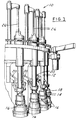
- FIG. 1 illustrates a conveyor system 10 that includes a circumferential array of spindles 12, each of which carries a chuck assembly 14 for engaging and retaining a hot glass container 16 and conveying the container between successive stages of a manufacturing process.
- Each spindle 12 has a collar 18 engaged by an arm 20 operated by a cam mechanism (not shown) for lowering the associated chuck 14 over a container, and then raising and/or lowering the chuck with the container retained therein.
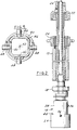
- FIG. 2 illustrates the construction of spindle 12 in greater detail, including the mating gears 22,24 for rotating chuck 14, as well as the vacuum tube 26 (FIGS. 1 and 2) that extends downwardly through each spindle 12 for applying vacuum to the associated chuck 14 for retaining a container therein.
- vacuum refers to application of sub-atmospheric pressure to the respective chucks 14.
- FIG. 3 illustrates chuck 14 in greater detail.
- a chuck body 28 of generally cylindrical construction has an upper end that receives vacuum tube 26.
- Chuck body 28 forms a generally cylindrical cavity 30 of diameter slightly greater than the diagonal dimension of containers 16.
- Cavity 30 has an outwardly flared open end 32 for receiving the closed end of a container 16.
- An apertured valve plate 34 is retained by screws 36 spaced from open end 32 for abutment with the closed end of container 16 received within chuck cavity 30.
- the chuck is of generally conventional construction.
- the cylindrical contour of chuck cavity 30 accommodates lack of angular orientation of the square cross section of each container 16, and the flared open end 32 is provided to accommodate slight axial misalignment between the container and the axis of the chuck.
- a circular transition plate 40 is mounted by an annular keeper 42 and a series of screws 44 adjacent to and coaxially with the open end 32 of chuck cavity 30 while permitting free rotation of plate 40 coaxially with chuck cavity 30.
- Transition plate 40 has a square central opening 46 of geometry closely coordinated with the square cross sectional geometry of containers 16, so that the containers may be closely received within opening 46 with only a small space between the periphery of opening 46 and the opposing surface of the container sidewall.
- Four arcuate guide fingers 48 are mounted on transition plate 40 by associated screws 50. Each finger 48 projects away from chuck body 28 and plate opening 46. As best seen in FIG. 5, fingers 48 are mounted to plate 40 in opposed pairs, with one finger being disposed along each lineal edge of plate opening 46.
- Each pair of fingers 48 is offset from the center line 52 of plate opening 46, which is coaxial with chuck opening 32, chuck cavity 30, vacuum plate 34 and vacuum tube 26.
- a cover shield 54 is mounted on chuck body 28 by screws 56 for enclosing fingers 48, keeper 42 and transition plate 40.
- arcuate guide fingers 48 In operation, as chuck 14 is lowered axially over a container 16 (or the container may be lifted into the chuck), the edges of the container where the sidewalls meet the bottom are initially engaged by arcuate guide fingers 48. These arcuate guide fingers slide along the edges of the container while simultaneously rotating plate 40 with respect to chuck body 28 so as to align square plate opening 46 with the square cross sectional contour of the container. Disposition of fingers 48 in offset pairs, as shown in FIG. 5, ensures that the four guide fingers will not simultaneously engage corners of the container, which could prevent rotation of the guide fingers and transition plate, and potentially jam the mechanism or damage the container.
- Guide fingers 48 thus rotate transition plate 40 to a position aligned with the cross sectional contour of container 16 as chuck 14 is initially lowered over the container.
- chuck 14 moves plate 40 over the container sidewalls, and brings the closed end of container 16 into abutment with valve plate 34.
- Application of vacuum through tube 26 and apertures 35 in plate 34 hold the container bottom against the valve plate. Close fit between transition plate opening 46 and the opposing sidewalls of container 16 restricts flow of air through opening 46 around the container sidewall, and thereby greatly improves the ability of chuck 14 to retain and hold the container.
Landscapes
- Chemical & Material Sciences (AREA)
- Engineering & Computer Science (AREA)
- Materials Engineering (AREA)
- Organic Chemistry (AREA)
- Mechanical Engineering (AREA)
- Manipulator (AREA)
- Re-Forming, After-Treatment, Cutting And Transporting Of Glass Products (AREA)
- Lining Or Joining Of Plastics Or The Like (AREA)
Applications Claiming Priority (2)
| Application Number | Priority Date | Filing Date | Title |
|---|---|---|---|
| US07/907,948 US5251919A (en) | 1992-07-02 | 1992-07-02 | Apparatus for holding square articles |
| US907948 | 1992-07-02 |
Publications (3)
| Publication Number | Publication Date |
|---|---|
| EP0577032A2 true EP0577032A2 (fr) | 1994-01-05 |
| EP0577032A3 EP0577032A3 (fr) | 1995-05-24 |
| EP0577032B1 EP0577032B1 (fr) | 1999-04-21 |
Family
ID=25424909
Family Applications (1)
| Application Number | Title | Priority Date | Filing Date |
|---|---|---|---|
| EP93110233A Expired - Lifetime EP0577032B1 (fr) | 1992-07-02 | 1993-06-26 | Dispositif pour tenir des articles rectangulaires |
Country Status (5)
| Country | Link |
|---|---|
| US (1) | US5251919A (fr) |
| EP (1) | EP0577032B1 (fr) |
| JP (1) | JPH06104309B2 (fr) |
| CA (1) | CA2099292C (fr) |
| MX (1) | MX9303960A (fr) |
Families Citing this family (9)
| Publication number | Priority date | Publication date | Assignee | Title |
|---|---|---|---|---|
| ATE375946T1 (de) * | 2000-06-08 | 2007-11-15 | Bosch Gmbh Robert | Greifvorrichtung zum erfassen von gegenständen und verfahren zum betreiben derselben |
| US7281739B2 (en) * | 2004-09-01 | 2007-10-16 | Delaware Capital Formation, Inc. | Adjustable mount for vacuum cup with offset mounting post and swivel |
| US7798546B2 (en) * | 2006-11-09 | 2010-09-21 | Delaware Capital Formation, Inc. | Material handling device with level indicator |
| DE102014216638B4 (de) * | 2014-08-21 | 2016-08-11 | J. Schmalz Gmbh | Spannvorrichtung mit Rastkupplung und integriertem Saugkanal zum Fixieren eines Werkstücks |
| CN111659582B (zh) * | 2020-05-09 | 2025-04-01 | 珠海市宏泰机械科技有限公司 | 一种电感装配机构 |
| CN112224876A (zh) * | 2020-09-10 | 2021-01-15 | 翔实光电科技(昆山)有限公司 | 一种用于大尺寸超薄玻璃或液晶屏取放的吸盘组合 |
| CN113118994B (zh) * | 2021-04-08 | 2022-06-21 | 常州机电职业技术学院 | 一种5g通信模块制作用的定位治具及其使用方法 |
| CN113213161A (zh) * | 2021-06-10 | 2021-08-06 | 四会市晶宝玻璃有限公司 | 一种用于玻璃制品生产设备的自动夹杯机构及其使用方法 |
| CN113478510B (zh) * | 2021-06-30 | 2022-12-02 | 江西机电职业技术学院 | 一种机械抓手 |
Family Cites Families (4)
| Publication number | Priority date | Publication date | Assignee | Title |
|---|---|---|---|---|
| US1744313A (en) * | 1924-11-07 | 1930-01-21 | Libbey Glass Mfg Co | Vacuum chuck |
| US2462988A (en) * | 1943-05-22 | 1949-03-01 | Hartford Empire Co | Method of making all-glass sealed packages |
| GB2239857A (en) * | 1990-01-12 | 1991-07-17 | Automation Tooling Syst | Rotatable suction head for article-handling apparatus |
| US5172922A (en) * | 1991-04-25 | 1992-12-22 | Digital Equipment Corporation | Self aligning vacuum nozzle |
-
1992
- 1992-07-02 US US07/907,948 patent/US5251919A/en not_active Expired - Lifetime
-
1993
- 1993-06-26 EP EP93110233A patent/EP0577032B1/fr not_active Expired - Lifetime
- 1993-06-28 CA CA002099292A patent/CA2099292C/fr not_active Expired - Fee Related
- 1993-06-30 MX MX9303960A patent/MX9303960A/es unknown
- 1993-07-02 JP JP5188667A patent/JPH06104309B2/ja not_active Expired - Lifetime
Also Published As
| Publication number | Publication date |
|---|---|
| US5251919A (en) | 1993-10-12 |
| MX9303960A (es) | 1994-04-29 |
| EP0577032A3 (fr) | 1995-05-24 |
| JPH0655479A (ja) | 1994-03-01 |
| JPH06104309B2 (ja) | 1994-12-21 |
| CA2099292C (fr) | 2002-07-16 |
| CA2099292A1 (fr) | 1994-01-03 |
| EP0577032B1 (fr) | 1999-04-21 |
Similar Documents
| Publication | Publication Date | Title |
|---|---|---|
| US5251919A (en) | Apparatus for holding square articles | |
| CN112192219A (zh) | 电磁阀组装生产线 | |
| CA1194293A (fr) | Methode et dispositif de mise a joint | |
| WO1994015355A2 (fr) | Module de transport de tranche avec support de tranche rotatif et extensible horizontalement | |
| GB2343672A (en) | Wafer handler for multi-station tool | |
| CN113334076B (zh) | 电动撑杆芯杆组装设备 | |
| EP0565278A1 (fr) | Appareil pour manipuler les galettes semi-conductrices et méthode | |
| JP2002517088A (ja) | 半導体ウエハハンドリング用バッチ式エンドエフェクタ | |
| CN213702451U (zh) | 电磁阀组装生产线 | |
| JP2004175415A (ja) | キャッピング装置 | |
| US5456007A (en) | Assist method and apparatus for fitting close tolerance valves into bores | |
| US20040221811A1 (en) | Method and apparatus for processing wafers | |
| JPH03155619A (ja) | 真空処理装置 | |
| JPH03289420A (ja) | カートン取出し装置 | |
| CN213833637U (zh) | 一种瓶坯真空旋转吸附装置 | |
| JP3421358B2 (ja) | 搬送方法 | |
| CN120245045B (zh) | 一种引信生产用零件加工装置 | |
| USRE33641E (en) | Method and apparatus for proper registration of mating parts | |
| US5876179A (en) | Vacuum-controlled collet for manipulation of semiconductor parts | |
| CN114799824B (zh) | 胶塞自动移除装置 | |
| JPH04272026A (ja) | ワーク反転移載装置 | |
| KR200241559Y1 (ko) | 반도체웨이퍼 운반용 진공튀저 | |
| JP3558356B2 (ja) | 眼用レンズ製作用材の搬送装置 | |
| JP2001150379A (ja) | 物品の真空吸着搬送装置 | |
| JPH04115879A (ja) | コイルスプリング組付機 |
Legal Events
| Date | Code | Title | Description |
|---|---|---|---|
| PUAI | Public reference made under article 153(3) epc to a published international application that has entered the european phase |
Free format text: ORIGINAL CODE: 0009012 |
|
| AK | Designated contracting states |
Kind code of ref document: A2 Designated state(s): BE FR GB |
|
| PUAL | Search report despatched |
Free format text: ORIGINAL CODE: 0009013 |
|
| AK | Designated contracting states |
Kind code of ref document: A3 Designated state(s): BE FR GB |
|
| 17P | Request for examination filed |
Effective date: 19951109 |
|
| GRAG | Despatch of communication of intention to grant |
Free format text: ORIGINAL CODE: EPIDOS AGRA |
|
| 17Q | First examination report despatched |
Effective date: 19980716 |
|
| GRAG | Despatch of communication of intention to grant |
Free format text: ORIGINAL CODE: EPIDOS AGRA |
|
| GRAH | Despatch of communication of intention to grant a patent |
Free format text: ORIGINAL CODE: EPIDOS IGRA |
|
| GRAH | Despatch of communication of intention to grant a patent |
Free format text: ORIGINAL CODE: EPIDOS IGRA |
|
| GRAA | (expected) grant |
Free format text: ORIGINAL CODE: 0009210 |
|
| AK | Designated contracting states |
Kind code of ref document: B1 Designated state(s): BE FR GB |
|
| ET | Fr: translation filed | ||
| PG25 | Lapsed in a contracting state [announced via postgrant information from national office to epo] |
Ref country code: BE Free format text: LAPSE BECAUSE OF NON-PAYMENT OF DUE FEES Effective date: 19990630 |
|
| PG25 | Lapsed in a contracting state [announced via postgrant information from national office to epo] |
Ref country code: GB Free format text: LAPSE BECAUSE OF NON-PAYMENT OF DUE FEES Effective date: 19990721 |
|
| BERE | Be: lapsed |
Owner name: LIBBEY GLASS INC. Effective date: 19990630 |
|
| PLBE | No opposition filed within time limit |
Free format text: ORIGINAL CODE: 0009261 |
|
| STAA | Information on the status of an ep patent application or granted ep patent |
Free format text: STATUS: NO OPPOSITION FILED WITHIN TIME LIMIT |
|
| GBPC | Gb: european patent ceased through non-payment of renewal fee |
Effective date: 19990721 |
|
| 26N | No opposition filed | ||
| PGFP | Annual fee paid to national office [announced via postgrant information from national office to epo] |
Ref country code: FR Payment date: 20090617 Year of fee payment: 17 |
|
| REG | Reference to a national code |
Ref country code: FR Ref legal event code: ST Effective date: 20110228 |
|
| PG25 | Lapsed in a contracting state [announced via postgrant information from national office to epo] |
Ref country code: FR Free format text: LAPSE BECAUSE OF NON-PAYMENT OF DUE FEES Effective date: 20100630 |