EP0577086A1 - Installation pour le traitement de surface - Google Patents
Installation pour le traitement de surface Download PDFInfo
- Publication number
- EP0577086A1 EP0577086A1 EP93110384A EP93110384A EP0577086A1 EP 0577086 A1 EP0577086 A1 EP 0577086A1 EP 93110384 A EP93110384 A EP 93110384A EP 93110384 A EP93110384 A EP 93110384A EP 0577086 A1 EP0577086 A1 EP 0577086A1
- Authority
- EP
- European Patent Office
- Prior art keywords
- fluidized bed
- gas
- powder
- layer
- coarse particles
- Prior art date
- Legal status (The legal status is an assumption and is not a legal conclusion. Google has not performed a legal analysis and makes no representation as to the accuracy of the status listed.)
- Granted
Links
- 238000004381 surface treatment Methods 0.000 title claims abstract description 15
- 239000007789 gas Substances 0.000 claims abstract description 101
- 239000000843 powder Substances 0.000 claims abstract description 87
- 239000010410 layer Substances 0.000 claims abstract description 43
- 239000011362 coarse particle Substances 0.000 claims abstract description 40
- 239000002245 particle Substances 0.000 claims abstract description 31
- 239000000463 material Substances 0.000 claims abstract description 28
- 150000004820 halides Chemical class 0.000 claims abstract description 20
- 239000002344 surface layer Substances 0.000 claims abstract description 20
- 238000005054 agglomeration Methods 0.000 claims abstract description 17
- 230000002776 aggregation Effects 0.000 claims abstract description 17
- 229910045601 alloy Inorganic materials 0.000 claims abstract description 13
- 239000000956 alloy Substances 0.000 claims abstract description 13
- 229910052751 metal Inorganic materials 0.000 claims abstract description 13
- 239000002184 metal Substances 0.000 claims abstract description 13
- 239000000203 mixture Substances 0.000 claims abstract description 12
- 238000010438 heat treatment Methods 0.000 claims abstract description 7
- 239000011819 refractory material Substances 0.000 claims abstract description 5
- 230000001133 acceleration Effects 0.000 claims abstract description 4
- 230000005484 gravity Effects 0.000 claims abstract description 4
- PNEYBMLMFCGWSK-UHFFFAOYSA-N aluminium oxide Inorganic materials [O-2].[O-2].[O-2].[Al+3].[Al+3] PNEYBMLMFCGWSK-UHFFFAOYSA-N 0.000 claims description 13
- VYPSYNLAJGMNEJ-UHFFFAOYSA-N Silicium dioxide Chemical compound O=[Si]=O VYPSYNLAJGMNEJ-UHFFFAOYSA-N 0.000 claims description 12
- MCMNRKCIXSYSNV-UHFFFAOYSA-N Zirconium dioxide Chemical compound O=[Zr]=O MCMNRKCIXSYSNV-UHFFFAOYSA-N 0.000 claims description 12
- 150000004767 nitrides Chemical class 0.000 claims description 7
- 239000000377 silicon dioxide Substances 0.000 claims description 6
- 235000012239 silicon dioxide Nutrition 0.000 claims description 6
- GWEVSGVZZGPLCZ-UHFFFAOYSA-N Titan oxide Chemical compound O=[Ti]=O GWEVSGVZZGPLCZ-UHFFFAOYSA-N 0.000 claims description 3
- -1 ammonium halide Chemical class 0.000 claims description 3
- 239000003513 alkali Substances 0.000 claims description 2
- 229910001508 alkali metal halide Inorganic materials 0.000 claims description 2
- 229910001615 alkaline earth metal halide Inorganic materials 0.000 claims description 2
- 229910000039 hydrogen halide Inorganic materials 0.000 claims description 2
- 239000012433 hydrogen halide Substances 0.000 claims description 2
- 229910000765 intermetallic Inorganic materials 0.000 claims description 2
- 229910001507 metal halide Inorganic materials 0.000 claims description 2
- 150000005309 metal halides Chemical class 0.000 claims description 2
- 239000006104 solid solution Substances 0.000 claims description 2
- XKRFYHLGVUSROY-UHFFFAOYSA-N Argon Chemical compound [Ar] XKRFYHLGVUSROY-UHFFFAOYSA-N 0.000 description 12
- 238000005243 fluidization Methods 0.000 description 12
- IJGRMHOSHXDMSA-UHFFFAOYSA-N Atomic nitrogen Chemical compound N#N IJGRMHOSHXDMSA-UHFFFAOYSA-N 0.000 description 8
- 239000003795 chemical substances by application Substances 0.000 description 7
- 229910052786 argon Inorganic materials 0.000 description 6
- 239000008188 pellet Substances 0.000 description 5
- NLXLAEXVIDQMFP-UHFFFAOYSA-N Ammonia chloride Chemical compound [NH4+].[Cl-] NLXLAEXVIDQMFP-UHFFFAOYSA-N 0.000 description 4
- 238000000034 method Methods 0.000 description 4
- 229910052757 nitrogen Inorganic materials 0.000 description 4
- 230000015572 biosynthetic process Effects 0.000 description 3
- OKTJSMMVPCPJKN-UHFFFAOYSA-N Carbon Chemical compound [C] OKTJSMMVPCPJKN-UHFFFAOYSA-N 0.000 description 2
- XEEYBQQBJWHFJM-UHFFFAOYSA-N Iron Chemical compound [Fe] XEEYBQQBJWHFJM-UHFFFAOYSA-N 0.000 description 2
- PXHVJJICTQNCMI-UHFFFAOYSA-N Nickel Chemical compound [Ni] PXHVJJICTQNCMI-UHFFFAOYSA-N 0.000 description 2
- 229910000831 Steel Inorganic materials 0.000 description 2
- 235000019270 ammonium chloride Nutrition 0.000 description 2
- 229910052799 carbon Inorganic materials 0.000 description 2
- 238000005260 corrosion Methods 0.000 description 2
- 230000007797 corrosion Effects 0.000 description 2
- 229910052593 corundum Inorganic materials 0.000 description 2
- 230000003247 decreasing effect Effects 0.000 description 2
- 230000007246 mechanism Effects 0.000 description 2
- 230000002035 prolonged effect Effects 0.000 description 2
- 230000009467 reduction Effects 0.000 description 2
- 230000000717 retained effect Effects 0.000 description 2
- 239000010959 steel Substances 0.000 description 2
- 229910052720 vanadium Inorganic materials 0.000 description 2
- 229910001845 yogo sapphire Inorganic materials 0.000 description 2
- INZDTEICWPZYJM-UHFFFAOYSA-N 1-(chloromethyl)-4-[4-(chloromethyl)phenyl]benzene Chemical compound C1=CC(CCl)=CC=C1C1=CC=C(CCl)C=C1 INZDTEICWPZYJM-UHFFFAOYSA-N 0.000 description 1
- QGZKDVFQNNGYKY-UHFFFAOYSA-N Ammonia Chemical compound N QGZKDVFQNNGYKY-UHFFFAOYSA-N 0.000 description 1
- VYZAMTAEIAYCRO-UHFFFAOYSA-N Chromium Chemical compound [Cr] VYZAMTAEIAYCRO-UHFFFAOYSA-N 0.000 description 1
- 229910017060 Fe Cr Inorganic materials 0.000 description 1
- 229910002544 Fe-Cr Inorganic materials 0.000 description 1
- 229910002593 Fe-Ti Inorganic materials 0.000 description 1
- 229910000628 Ferrovanadium Inorganic materials 0.000 description 1
- RTAQQCXQSZGOHL-UHFFFAOYSA-N Titanium Chemical compound [Ti] RTAQQCXQSZGOHL-UHFFFAOYSA-N 0.000 description 1
- 229910001315 Tool steel Inorganic materials 0.000 description 1
- 239000012190 activator Substances 0.000 description 1
- 230000002411 adverse Effects 0.000 description 1
- 230000004075 alteration Effects 0.000 description 1
- 230000005587 bubbling Effects 0.000 description 1
- 239000003575 carbonaceous material Substances 0.000 description 1
- 239000007795 chemical reaction product Substances 0.000 description 1
- 229910052804 chromium Inorganic materials 0.000 description 1
- 239000011651 chromium Substances 0.000 description 1
- UPHIPHFJVNKLMR-UHFFFAOYSA-N chromium iron Chemical compound [Cr].[Fe] UPHIPHFJVNKLMR-UHFFFAOYSA-N 0.000 description 1
- 230000003292 diminished effect Effects 0.000 description 1
- 230000000694 effects Effects 0.000 description 1
- 239000001307 helium Substances 0.000 description 1
- 229910052734 helium Inorganic materials 0.000 description 1
- SWQJXJOGLNCZEY-UHFFFAOYSA-N helium atom Chemical compound [He] SWQJXJOGLNCZEY-UHFFFAOYSA-N 0.000 description 1
- 239000011261 inert gas Substances 0.000 description 1
- 229910052742 iron Inorganic materials 0.000 description 1
- PNXOJQQRXBVKEX-UHFFFAOYSA-N iron vanadium Chemical compound [V].[Fe] PNXOJQQRXBVKEX-UHFFFAOYSA-N 0.000 description 1
- 239000007769 metal material Substances 0.000 description 1
- 150000002739 metals Chemical class 0.000 description 1
- 229910052759 nickel Inorganic materials 0.000 description 1
- 230000008569 process Effects 0.000 description 1
- 239000010936 titanium Substances 0.000 description 1
- 229910052719 titanium Inorganic materials 0.000 description 1
- GPPXJZIENCGNKB-UHFFFAOYSA-N vanadium Chemical compound [V]#[V] GPPXJZIENCGNKB-UHFFFAOYSA-N 0.000 description 1
Images
Classifications
-
- F—MECHANICAL ENGINEERING; LIGHTING; HEATING; WEAPONS; BLASTING
- F27—FURNACES; KILNS; OVENS; RETORTS
- F27B—FURNACES, KILNS, OVENS OR RETORTS IN GENERAL; OPEN SINTERING OR LIKE APPARATUS
- F27B15/00—Fluidised-bed furnaces; Other furnaces using or treating finely-divided materials in dispersion
-
- B—PERFORMING OPERATIONS; TRANSPORTING
- B01—PHYSICAL OR CHEMICAL PROCESSES OR APPARATUS IN GENERAL
- B01J—CHEMICAL OR PHYSICAL PROCESSES, e.g. CATALYSIS OR COLLOID CHEMISTRY; THEIR RELEVANT APPARATUS
- B01J8/00—Chemical or physical processes in general, conducted in the presence of fluids and solid particles; Apparatus for such processes
- B01J8/18—Chemical or physical processes in general, conducted in the presence of fluids and solid particles; Apparatus for such processes with fluidised particles
- B01J8/24—Chemical or physical processes in general, conducted in the presence of fluids and solid particles; Apparatus for such processes with fluidised particles according to "fluidised-bed" technique
- B01J8/32—Chemical or physical processes in general, conducted in the presence of fluids and solid particles; Apparatus for such processes with fluidised particles according to "fluidised-bed" technique with introduction into the fluidised bed of more than one kind of moving particles
-
- C—CHEMISTRY; METALLURGY
- C23—COATING METALLIC MATERIAL; COATING MATERIAL WITH METALLIC MATERIAL; CHEMICAL SURFACE TREATMENT; DIFFUSION TREATMENT OF METALLIC MATERIAL; COATING BY VACUUM EVAPORATION, BY SPUTTERING, BY ION IMPLANTATION OR BY CHEMICAL VAPOUR DEPOSITION, IN GENERAL; INHIBITING CORROSION OF METALLIC MATERIAL OR INCRUSTATION IN GENERAL
- C23C—COATING METALLIC MATERIAL; COATING MATERIAL WITH METALLIC MATERIAL; SURFACE TREATMENT OF METALLIC MATERIAL BY DIFFUSION INTO THE SURFACE, BY CHEMICAL CONVERSION OR SUBSTITUTION; COATING BY VACUUM EVAPORATION, BY SPUTTERING, BY ION IMPLANTATION OR BY CHEMICAL VAPOUR DEPOSITION, IN GENERAL
- C23C16/00—Chemical coating by decomposition of gaseous compounds, without leaving reaction products of surface material in the coating, i.e. chemical vapour deposition [CVD] processes
- C23C16/44—Chemical coating by decomposition of gaseous compounds, without leaving reaction products of surface material in the coating, i.e. chemical vapour deposition [CVD] processes characterised by the method of coating
- C23C16/442—Chemical coating by decomposition of gaseous compounds, without leaving reaction products of surface material in the coating, i.e. chemical vapour deposition [CVD] processes characterised by the method of coating using fluidised bed process
-
- B—PERFORMING OPERATIONS; TRANSPORTING
- B22—CASTING; POWDER METALLURGY
- B22F—WORKING METALLIC POWDER; MANUFACTURE OF ARTICLES FROM METALLIC POWDER; MAKING METALLIC POWDER; APPARATUS OR DEVICES SPECIALLY ADAPTED FOR METALLIC POWDER
- B22F2998/00—Supplementary information concerning processes or compositions relating to powder metallurgy
-
- Y—GENERAL TAGGING OF NEW TECHNOLOGICAL DEVELOPMENTS; GENERAL TAGGING OF CROSS-SECTIONAL TECHNOLOGIES SPANNING OVER SEVERAL SECTIONS OF THE IPC; TECHNICAL SUBJECTS COVERED BY FORMER USPC CROSS-REFERENCE ART COLLECTIONS [XRACs] AND DIGESTS
- Y10—TECHNICAL SUBJECTS COVERED BY FORMER USPC
- Y10S—TECHNICAL SUBJECTS COVERED BY FORMER USPC CROSS-REFERENCE ART COLLECTIONS [XRACs] AND DIGESTS
- Y10S118/00—Coating apparatus
- Y10S118/05—Fluidized bed
Definitions
- This invention relates to an apparatus for surface treatment which includes a fluidized bed furnace. More particularly, it is an apparatus which can prevent the agglomeration of a powder forming a fluidized bed which will obstruct its uniform fluidization, and can also protect a gas distributor from a highly reactive powder, or atmosphere.
- a fluidized bed furnace is supplied with a fluidizable powder mixture (hereinafter referred to as fluidized bed powders) consisting of a powder of alumina, or other refractory material (hereinafter referred to as a fluidizing agent), and a powder of a metal, or alloy, or both for forming a carbide, nitride, or other surface layer (hereinafter referred to as a surface layer-forming powder), and a fluidizing gas, such as argon, is introduced into the furnace to fluidize the fluidized bed powders to form a fluidized bed.
- a fluidizing gas such as argon
- the reaction of the halide and the surface layer-forming powder produces the gas of a halide of the surface layer-forming element, and the reaction of the halide gas with carbon or nitrogen in the material to be treated forms the surface layer. It has, however, often been the case that during the process of formation of the surface layer, the agglomeration of a part of the fluidized bed powders occurs to form a mass in the fluidized bed, depending on the conditions employed for surface treatment, including the amount of the halide gas produced and the flow rate of the fluidizing gas.
- the powders around the mass fail to be satisfactorily fluidized, and the fluidized bed lacks uniformity in temperature, and has, therefore, only a limited area in which it can form a uniform surface layer on the material to be treated.
- the mass often interferes with a jig employed for holding the material to be treated in the furnace, and thereby disables it to be held in a proper position. Therefore, it is often necessary to interrupt the operation for surface treatment to remove any such mass.
- the agglomeration of the powders in the fluidized bed can be diminished by increasing the flow rate of the fluidizing gas to achieve a higher degree of fluidization, or by decreasing the amount of the halide to be added. Both of these steps are, however, impractical, since the increased consumption of the fluidizing gas adds to the cost of the surface treatment, and the changes in the necessary conditions for the treatment, including the concentration of the reactive gas in the fluidized bed, result in the formation of a surface layer having an undesirably small, or uneven thickness.
- the furnace employed by the known methods is provided with a gas distributor for distributing the fluidizing gas through the fluidized bed.
- the gas distributor is, however, in contact with the fluidized bed, and is, therefore, exposed to the halide gas in the fluidized bed. It is very likely that the gas distributor may be corroded by the halide gas, or that the fine openings thereof may be clogged with the reaction product. Such corrosion and clogging lower the function of the gas distributor.
- an object of this invention to provide an apparatus for surface treatment which can prevent the agglomeration of a powder forming a fluidized bed irrespective of the flow rate of a fluidizing gas, and other conditions employed for treatment, and can also protect a gas distributor from direct exposure to a highly reactive powder, or atmosphere, and thereby from corrosion, or other inconveniences.
- the inventors of this invention have made a detailed study of the mechanism causing the agglomeration of a powder forming a fluidized bed which exerts an adverse effect on the surface treatment of the material placed therein, and possible means for overcoming the problem.
- a fluidizing gas fails to flow uniformly, and leaves a part of surface layer-forming metal or alloy powders virtually immobile and in contact with one another for a prolonged time, those powders react and combine with one another to form a mass; that the mass grows by including powders of e.g.
- alumina as a fluidizing agent; and that it is possible to ensure the uniform flow of the fluidizing gas and there avoid the stagnation of powders in any part of the fluidized bed and the formation of any mass if a layer of coarse particles which are sufficiently heavy not to be movable by the fluidizing gas is provided above a gas distributor.
- an apparatus for surface treatment which comprises: a furnace having an inlet for a fluidizing gas, a gas distributor for distributing the fluidizing gas arriving from its inlet, and a gas outlet; a fluidizable powder mixture placed in the furnace above the gas distributor, composed of a powder of alumina, or other refractory material, and a powder of a metal, or alloy, or both for forming a surface layer on the material to be treated; the fluidizable powder mixture being fluidized by the fluidizing gas to form a fluidized bed; a device for heating the furnace; and a layer of coarse particles disposed between the gas distributor and the fluidized bed, and having a mean diameter, D(m), as defined below: (1650V ⁇ /PG) 1/2 ⁇ D ⁇ 6.5d (1) where
- the layer of coarse particles having the mean diameter as defined by the above formula (1), and disposed between the gas distributor and the fluidized bed, serves to enable the fluidizing gas to flow uniformly through the fluidized bed and thereby prevent the stagnation of the powders in any part of the bed.
- the following is a presumably, though not definitely, correct explanation of the mechanism which enables the layer of coarse particles to produce the result as described.
- the expression "6.5d” which defines the maximum D value in formula (1) gives the mean diameter D of the coarse particles which allow the passage of the surface layer-forming powders having a mean diameter expressed as d. Accordingly, the layer of coarse particles having a diameter which is smaller than the D value given by the expression "6.5d” can decrease the passage of the surface layer-forming powders therethrough. In other words, the layer of coarse particles having a diameter which is greater than 6.5d has larger interstices among the particles, and allows a larger amount of surface layer-forming powders to enter the interstices and stay therein to hinder the flow of the fluidizing gas thereby cause the local stagnation of the powders in the fluidized bed.
- the layer of coarse particles having a mean diameter D falling within the range as defined by formula (1) has small interstices among the particles, and contains a large number of particles, and thereby enables the improved distribution of gas and thereby the uniform fluidization of the powders in the fluidized bed.
- the absence of any stagnation of the powders in the fluidized bed means the absence of any prolonged contact of the powders in any part of the fluidized bed, and makes it possible to restrict the possibility of any reaction between the metal, or the like powders and thereby prevent the agglomeration thereof.
- the layer of coarse particles isolates the powders of the fluidized bed from the gas distributor, and a difference in pressure which is produced between the layer of coarse particles and the fluidized bed powders prevents the back flow of the fluidizing gas and the halide gas through the layer of coarse particles. Therefore, there is no possibility of the gas distributor being exposed to the gases from the fluidized bed.
- the layer of coarse particles prevents the stagnation of the powders in any part of the fluidized bed and thereby the agglomeration thereof, as hereinabove stated.
- the apparatus of this invention therefore, makes it possible to avoid various problems including any insufficient fluidization that would result from the agglomeration of powders in the fluidized bed, the lack of uniformity in temperature of the fluidized bed that would result from any insufficient fluidization, any reduction in the effective area for treatment and any improper positioning of the jig for the material to be treated in the fluidized bed that would result from an increase in the agglomerated portion of the fluidized bed, and the necessity of interrupting treatment to remove any mass of powders from the fluidized bed, and thereby ensures an efficient surface treatment.
- the layer of coarse particles also protect the gas distributor from a highly reactive powder, or atmosphere in the fluidized bed.
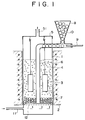
- Fig. 1 is a schematic representation of an apparatus for surface treatment as used in Example 1 which will hereinafter be described.
- the apparatus for surface treatment of this invention may comprise a fluidized bed furnace which is usually employed for dying, incineration, reduction, or other purposes. Therefore, it may, for example, comprise a furnace 1 having an inlet 11 for a fluidizing gas, such as argon, at its bottom, provided with a gas distributor 12 inwardly of the inlet 11, and surrounded by a heater 2 for heating a fluidized bed, as shown in Fig. 1.
- the furnace is provided at its top with a cover 5 having a gas outlet 51, and the cover 5 is removable to enable the material to be treated 3 to be charged into the furnace, or discharged therefrom.
- the furnace contains a layer 7 of coarse particles immediately above the gas distributor 12, and a fluidized bed 4 above the layer 7.
- the furnace is also provided with a device 6 for supplying a halide to the bottom thereof.
- the furnace may further be provided with, for example, a pipe through which a gas containing nitrogen is supplied from an external source of supply into the furnace, if it is employed for forming a nitride layer on the material to be treated.
- the fluidized bed powders consist of a refractory powder (i.e. fluidizing agent), and a powder of a metal, or alloy, or both for forming a surface layer (i.e. surface-layer forming powder).
- the fluidizing agent may be of any material that does not react with any of the elements constituting the material to be treated, and the surface layer-forming powder. It may, for example, be of alumina (Al2O3), silicon dioxide (SiO2), titanium dioxide (TiO2), or zirconia (ZrO2), or a mixture thereof.
- the surface layer-forming powder may be of a metal, or alloy, or both which can form a carbide, nitride, carbonitride, solid solution, intermetallic compound, etc. on the material to be treated. Therefore, it may, for example, be of a metal which easily combines with carbon or nitrogen to form a carbide, or nitride, such as chromium, vanadium or titanium, or an alloy such as Fe-Cr, Fe-V or Fe-Ti. It is also possible to use a plurality of metals or alloys together.
- the surface layer-forming metal or alloy powder preferably has a particle diameter of 0.5 to 1.2 x 10 ⁇ 4 m (80 to 350 mesh). It preferably has a mean particle diameter d of 0.5 to 1.2 x 10 ⁇ 4 m.
- the proportions of the fluidizing agent and the surface layer-forming powder may depend on, for example, the kind of the surface layer to be formed, and its thickness, it is usually appropriate to employ the surface layer-forming powder in the proportion of 2 to 80% by weight of the fluidizing agent.
- the coarse particles forming the layer 7 may be of any material that does not react with the fluidized bed powders, or any gas produced in the fluidized bed. It is, however, preferable to employ particles of a refractory material, such as alumina (Al2O3), silicon dioxide (SiO2), titanium dioxide (TiO2) or zirconia (ZrO2), or a mixture thereof.
- alumina Al2O3
- SiO2 silicon dioxide
- TiO2 titanium dioxide
- ZrO2 zirconia
- the coarse particles are required to have a mean diameter D as defined by formula (1) above.
- the coarse particles are not required to stay immobile, unless they move heavily to and away from the fluidized bed, but their two-dimensional movement is rather desirable for the uniform flow of the fluidizing gas.
- the layer of coarse particles may include still greater particles, particularly adjacent to the gas distributor, so that a still smaller loss of pressure may be achieved.
- the layer of coarse particles has a thickness of 5 to 300 mm. If its thickness is smaller than 5 mm, it cannot uniformly distribute the fluidizing gas leaving the gas distributor. If its thickness is larger than 300 mm, it creates an undesirably greater loss of pressure which calls for the supply of a larger amount of gas to achieve the same level of fluidizatioin, while no such increase in thickness is expected to produce any correspondingly improved result in preventing the agglomeration of the powders in the fluidized bed.
- the heater 2 surrounding the furnace 1 is usually an electric furnace, though it may alternatively be possible to employ any other appopriate device for heating the fluidized bed.
- An inert gas such as an argon
- a reactive gas containing nitrogen such as an ammonia gas
- the flow rate and speed of the fluidizing gas in the fluidized bed are so selected as to active satisfactory fluidization. If they are too low, the insufficiency of fluidization results in the fluidized bed not having a uniform temperature distribution. If they are too high, a larger amount of gas is needed, and the gas causes heavy bubbling and makes it difficult to continue any satisfactory operation.
- the fluidizing gas has a viscosity coefficient of, for example, 6.3 x 10 ⁇ 5 kg/m ⁇ s in case of argon, or 5.1 x 10 ⁇ 5 kg/m ⁇ s in case of helium, at 1000°C.
- the material to be treated depends on the surface layer to be formed thereon. It is usually a metallic material, such as iron, steel or nickel, or a nonmetallic material, such as an ultrahard alloy, or a carbonaceous material.
- the halide may be of any composition if it can produce a halide gas which reacts with the surface layer-forming powder to enable it to form a surface layer on the material to be treated. It is possible to use, for example, an ammonium halide, a metal halide, an alkali or alkaline earth metal halide, or hydrogen halide, or a mixture thereof.
- the halide is used in the form of a powder, pellets, or gas, or a mixture thereof.
- the halide can be added to the powders forming the fluidized bed before the furnace is heated, it is usual practice to employ pellets and supply them into the fluidized bed through the pipe 6, as shown in Fig. 1.
- the amount of the halide to be added depends on, among others, the kind of the surface layer to be formed, and its thickness.
- the surface treatment is usually conducted by heating at a temperature of 400 to 1200°C for 1 to 100 hours.
- the layer of powders above the layer of coarse particles is fluidized by a fluidizing gas to form a fluidized bed, and the material to be treated is placed in the fluidized bed, and the fluidized bed is heated in the presence of a halide, whereby a surface layer is formed on the material to be treated.
- the apparatus as shown in Fig. 1 was used to form a carbide layer on a steel surface.
- the furnace 1 had an inside diameter of 50 mm.
- the layer 7 of coarse particles was of alumina, and had a thickness of about 100 mm.
- the layer of fluidized bed powders had a weight of 1000 g, which were a mixture of alumina powder having a mean diameter of 1.8 x 10 ⁇ 4 m and ferrovanadium powder having a mean diameter of 1.2 x 10 ⁇ 4 m.
- Argon gas was supplied into the furnace 1 through the gas inlet 11 and the gas distributor 12 at a flow rate of 12 liters per minute to fluidize the particles above the layer 7 to form a fluidized bed 4 having a thickness of about 260 mm.
- the alumina particles forming the layer 7 of coarse particles had a diameter so selected by calculation as to satisfy the range of formula (1).
- the calculation of the value given by the lefthand expression in formula (1) was made by employing 0.10 m/s as the velocity V of the fluidizing argon gas, 6.3 x 10 ⁇ 5 kg/m ⁇ s as its viscosity coefficient ⁇ , 4.08 x 10³ kg/m3 as the mean density P of the coarse alumina particles, and 9.8 m/s2 as the acceleration of gravity G. It was 5.1 x 10 ⁇ 4 m, while the righthand expression in formula (1) gave a value of 7.8 x 10 ⁇ 4 m.
- the furnace 1 was closed by the cover 5 having its gas outlet 51 connected to an exhaust gas disposal apparatus not shown, and the fluidized bed 4 was heated by the heater 2.
- the fluidized bed shows a higher degree of fluidization with an elevation in temperature if the fluidizing gas is supplied at a constant rate. Therefore, the flow rate of the fluidizing gas was gradually decreased with an elevation in temperature of the fluidized bed, so that the fluidizing gas might be supplied at a rate of 2.6 liters per minute when the bed had a temperature of 1000°C.
- the bed showed substantially the same degree of fluidization at the temperature of 1000°C as at room temperature.
- pieces of cold rolled tool steel known as SKD 11 were placed in the fluidized bed 4 as the material to be treated 3.
- a hopper 8 was charged with ammonium chloride pellets 10 employed as activator, and having a diameter of 5 x 10 ⁇ 3 m, and the pellets 10 leaving the hopper 8 at its bottom were pushed by a rod 9 so as to drop down the pipe 6 at an average rate of 0.8% by weight per hour relative to fluidized bed powders. After two hours of operation, the cover 5 was removed, and the materials 3 which had been treated were discharged from the furnace 1, and air cooled to room temperature.
- the heater 2 was turned off, while the supply of the fluidizing gas was continued, and after the furnace 1 had been cooled to room temperature, the fluidized bed powder were immediately removed from the furnace 1, and put through a 1.2 mm (14-mesh) sieve. The masses of powders retained on the sieve were weighed as a measure of agglomeration.
- the particles having a mean diameter of 2.1 x 10 ⁇ 4 m were, however, too small to resist fluidization and protect the gas distributor from exposure to the powders and gases from the fluidized bed.
- Table 1 Mean diameter of coarse particles (x 10 ⁇ 4 m) Weight of agglomerated powders (g) 2.1 0 6 0 10 7 20 17
- the treatment for forming a carbide surface layer was made by repeating Example 1, except for employing a furnace having an inside diameter of 200 mm, a layer of coarse particles having a thickness of 100 mm, a fluidized bed having a thickness of 600 mm, and supplying ammonium chloride pellets at an average rate of 0.01% by weight per hour relative to the fluidized bed powders, and the fluidizing gas at a flow rate of 40 liters per minute at 1000°C.
- the lefthand expression in formula (1) gave a value of 4.9 x 10 ⁇ 4 m.
- Example 2 Comparison was made by employing four types of layer 7 consisting of diametrically different coarse particles, as in Example 1. The results are shown in Table 2 below. There was a large amount of agglomeration when the layer 7 was of particles having mean diameters of 10 x 10 ⁇ 4 and 20 x 10 ⁇ 4 m which were larger than the range as defined by formula (1), but there was no agglomeration when the layer 7 was of particles having a mean diameter of 6 x 10 ⁇ 4 m or 2.1 x 10 ⁇ 4 falling within, or smaller than the range, respectively. The particles having a mean diameter of 2.1 x 10 ⁇ 4 m were, however, too small to resist fluidization and protect the gas distributor from the powders and gases from the fluidized bed, as in Example 1.
Landscapes
- Chemical & Material Sciences (AREA)
- Engineering & Computer Science (AREA)
- Chemical Kinetics & Catalysis (AREA)
- Mechanical Engineering (AREA)
- Organic Chemistry (AREA)
- General Engineering & Computer Science (AREA)
- General Chemical & Material Sciences (AREA)
- Dispersion Chemistry (AREA)
- Materials Engineering (AREA)
- Metallurgy (AREA)
- Combustion & Propulsion (AREA)
- Devices And Processes Conducted In The Presence Of Fluids And Solid Particles (AREA)
- Crucibles And Fluidized-Bed Furnaces (AREA)
- Cleaning And De-Greasing Of Metallic Materials By Chemical Methods (AREA)
Applications Claiming Priority (2)
| Application Number | Priority Date | Filing Date | Title |
|---|---|---|---|
| JP197602/92 | 1992-06-30 | ||
| JP19760292 | 1992-06-30 |
Publications (2)
| Publication Number | Publication Date |
|---|---|
| EP0577086A1 true EP0577086A1 (fr) | 1994-01-05 |
| EP0577086B1 EP0577086B1 (fr) | 1999-03-24 |
Family
ID=16377209
Family Applications (1)
| Application Number | Title | Priority Date | Filing Date |
|---|---|---|---|
| EP93110384A Expired - Lifetime EP0577086B1 (fr) | 1992-06-30 | 1993-06-29 | Procédé pour le traitement de surface |
Country Status (6)
| Country | Link |
|---|---|
| US (1) | US5620521A (fr) |
| EP (1) | EP0577086B1 (fr) |
| JP (1) | JP3189507B2 (fr) |
| DE (1) | DE69324072T2 (fr) |
| DK (1) | DK0577086T3 (fr) |
| ES (1) | ES2132153T3 (fr) |
Cited By (1)
| Publication number | Priority date | Publication date | Assignee | Title |
|---|---|---|---|---|
| DE4443914A1 (de) * | 1994-12-09 | 1996-06-13 | Bayerische Motoren Werke Ag | Thermochemische Wärmebehandlung eines Metall-Bauteiles mittels Diffusion eines Elementes in einer Wirbelbett-Vorrichtung |
Families Citing this family (9)
| Publication number | Priority date | Publication date | Assignee | Title |
|---|---|---|---|---|
| US7621887B2 (en) * | 2000-10-10 | 2009-11-24 | Meridian Medical Technologies, Inc. | Wet/dry automatic injector assembly |
| US6506048B1 (en) * | 2001-11-01 | 2003-01-14 | Procedyne Corp. | Apparatus and method for transferring heat treated parts |
| JP2006506525A (ja) * | 2002-11-15 | 2006-02-23 | ユニバーシティ・オブ・ユタ・リサーチ・ファウンデーション | チタン表面上の一体型ホウ化チタンコーティングおよび関連方法 |
| US7459105B2 (en) * | 2005-05-10 | 2008-12-02 | University Of Utah Research Foundation | Nanostructured titanium monoboride monolithic material and associated methods |
| CN101268209B (zh) * | 2005-07-21 | 2012-07-18 | 哈德技术有限公司 | 金属物体的双重表面处理 |
| CN1962886A (zh) * | 2006-11-23 | 2007-05-16 | 中冶华天工程技术有限公司 | 一种合金化微调方法 |
| US7905433B2 (en) * | 2007-06-20 | 2011-03-15 | New Jersey Institute Of Technology | Systems and methods for reducing electrostatic charge in a fluidized bed |
| US20100176339A1 (en) * | 2009-01-12 | 2010-07-15 | Chandran K S Ravi | Jewelry having titanium boride compounds and methods of making the same |
| US9585199B2 (en) * | 2013-10-30 | 2017-02-28 | Atomic Energy Council—Institute of Nuclear Energy Research | Hybrid heating apparatus applicable to the moving granular bed filter |
Citations (4)
| Publication number | Priority date | Publication date | Assignee | Title |
|---|---|---|---|---|
| EP0166216A2 (fr) * | 1984-05-28 | 1986-01-02 | Kabushiki Kaisha Toyota Chuo Kenkyusho | Procédé de formation d'une couche de nitrure |
| EP0252480A2 (fr) * | 1986-07-07 | 1988-01-13 | Kabushiki Kaisha Toyota Chuo Kenkyusho | Procédé et appareil pour le traitement de surfaces |
| EP0303191A2 (fr) * | 1987-08-12 | 1989-02-15 | Kabushiki Kaisha Toyota Chuo Kenkyusho | Procédé et appareil pour le traitement d'une surface |
| EP0471276A1 (fr) * | 1990-08-10 | 1992-02-19 | Kabushiki Kaisha Toyota Chuo Kenkyusho | Procédé de fabrication d'un revêtement en nitrure ou carbonitrure |
Family Cites Families (7)
| Publication number | Priority date | Publication date | Assignee | Title |
|---|---|---|---|---|
| US4217851A (en) * | 1979-08-27 | 1980-08-19 | American Cyanamid Company | Tablet coating apparatus |
| US4314525A (en) * | 1980-03-03 | 1982-02-09 | California Institute Of Technology | Fluidized bed silicon deposition from silane |
| CA1164632A (fr) * | 1981-10-19 | 1984-04-03 | Jorg-Hein Walling | Lit fluidisable |
| DE3431044A1 (de) * | 1984-08-23 | 1986-03-06 | Elektroschmelzwerk Kempten GmbH, 8000 München | Verfahren zum borieren von metall und metall-legierungen mittels fester boriermittel |
| JPS6280258A (ja) * | 1985-10-03 | 1987-04-13 | Toyota Central Res & Dev Lab Inc | 表面処理方法及びその装置 |
| US4806387A (en) * | 1986-08-05 | 1989-02-21 | Toyota Jidosha Kabushiki Kaisha | Method for coating metal part with synthetic resin |
| US5236503A (en) * | 1991-10-28 | 1993-08-17 | Glatt Air Techniques, Inc. | Fluidized bed with spray nozzle shielding |
-
1993
- 1993-06-11 JP JP16633293A patent/JP3189507B2/ja not_active Expired - Lifetime
- 1993-06-29 DE DE69324072T patent/DE69324072T2/de not_active Expired - Fee Related
- 1993-06-29 DK DK93110384T patent/DK0577086T3/da active
- 1993-06-29 EP EP93110384A patent/EP0577086B1/fr not_active Expired - Lifetime
- 1993-06-29 ES ES93110384T patent/ES2132153T3/es not_active Expired - Lifetime
-
1995
- 1995-02-10 US US08/386,230 patent/US5620521A/en not_active Expired - Lifetime
Patent Citations (4)
| Publication number | Priority date | Publication date | Assignee | Title |
|---|---|---|---|---|
| EP0166216A2 (fr) * | 1984-05-28 | 1986-01-02 | Kabushiki Kaisha Toyota Chuo Kenkyusho | Procédé de formation d'une couche de nitrure |
| EP0252480A2 (fr) * | 1986-07-07 | 1988-01-13 | Kabushiki Kaisha Toyota Chuo Kenkyusho | Procédé et appareil pour le traitement de surfaces |
| EP0303191A2 (fr) * | 1987-08-12 | 1989-02-15 | Kabushiki Kaisha Toyota Chuo Kenkyusho | Procédé et appareil pour le traitement d'une surface |
| EP0471276A1 (fr) * | 1990-08-10 | 1992-02-19 | Kabushiki Kaisha Toyota Chuo Kenkyusho | Procédé de fabrication d'un revêtement en nitrure ou carbonitrure |
Cited By (1)
| Publication number | Priority date | Publication date | Assignee | Title |
|---|---|---|---|---|
| DE4443914A1 (de) * | 1994-12-09 | 1996-06-13 | Bayerische Motoren Werke Ag | Thermochemische Wärmebehandlung eines Metall-Bauteiles mittels Diffusion eines Elementes in einer Wirbelbett-Vorrichtung |
Also Published As
| Publication number | Publication date |
|---|---|
| DE69324072D1 (de) | 1999-04-29 |
| JPH0673525A (ja) | 1994-03-15 |
| JP3189507B2 (ja) | 2001-07-16 |
| ES2132153T3 (es) | 1999-08-16 |
| DE69324072T2 (de) | 1999-12-09 |
| EP0577086B1 (fr) | 1999-03-24 |
| DK0577086T3 (da) | 2000-06-05 |
| US5620521A (en) | 1997-04-15 |
Similar Documents
| Publication | Publication Date | Title |
|---|---|---|
| KR930009353B1 (ko) | 표면 처리방법 및 이에 사용되는 장치 | |
| CA1336150C (fr) | Methode et appareil utilises dans le traitement de surface | |
| KR100252406B1 (ko) | 표면처리방법 | |
| EP0577086B1 (fr) | Procédé pour le traitement de surface | |
| US4686117A (en) | Method of forming a carbide layer | |
| WO2012065220A1 (fr) | Traitement de surface d'objets métalliques | |
| AU587848B2 (en) | Surface treating method and apparatus | |
| Yen et al. | Nickel and copper deposition on fine alumina particles by using the chemical vapor deposition-circulation fluidized bed reactor technique | |
| EP1165852A1 (fr) | Procede et appareil de traitement de surface | |
| EP0443659B1 (fr) | Procédé de revêtement de poudres et procédé de préparation d'articles métalliques à partir de cette poudre | |
| JPH076052B2 (ja) | 表面処理方法及びその装置 | |
| JPH10218612A (ja) | 窒化ケイ素粉末の製造方法 | |
| JP3852652B2 (ja) | 鋼の冷却方法 | |
| JPS59107990A (ja) | 炭素を含む材料の炭化物被覆方法 | |
| JPH07268429A (ja) | 流動層予備還元装置の操業方法 | |
| JPS60258470A (ja) | 炭化物被覆方法 | |
| AU2783500A (en) | Surface treatment method and treatment apparatus | |
| Tachikawa et al. | Apparatus for surface treatment |
Legal Events
| Date | Code | Title | Description |
|---|---|---|---|
| PUAI | Public reference made under article 153(3) epc to a published international application that has entered the european phase |
Free format text: ORIGINAL CODE: 0009012 |
|
| AK | Designated contracting states |
Kind code of ref document: A1 Designated state(s): DE DK ES FR GB SE |
|
| 17P | Request for examination filed |
Effective date: 19931130 |
|
| 17Q | First examination report despatched |
Effective date: 19941207 |
|
| GRAG | Despatch of communication of intention to grant |
Free format text: ORIGINAL CODE: EPIDOS AGRA |
|
| GRAG | Despatch of communication of intention to grant |
Free format text: ORIGINAL CODE: EPIDOS AGRA |
|
| GRAH | Despatch of communication of intention to grant a patent |
Free format text: ORIGINAL CODE: EPIDOS IGRA |
|
| GRAH | Despatch of communication of intention to grant a patent |
Free format text: ORIGINAL CODE: EPIDOS IGRA |
|
| GRAA | (expected) grant |
Free format text: ORIGINAL CODE: 0009210 |
|
| AK | Designated contracting states |
Kind code of ref document: B1 Designated state(s): DE DK ES FR GB SE |
|
| PG25 | Lapsed in a contracting state [announced via postgrant information from national office to epo] |
Ref country code: SE Free format text: THE PATENT HAS BEEN ANNULLED BY A DECISION OF A NATIONAL AUTHORITY Effective date: 19990324 |
|
| REF | Corresponds to: |
Ref document number: 69324072 Country of ref document: DE Date of ref document: 19990429 |
|
| ET | Fr: translation filed | ||
| REG | Reference to a national code |
Ref country code: ES Ref legal event code: FG2A Ref document number: 2132153 Country of ref document: ES Kind code of ref document: T3 |
|
| PLBE | No opposition filed within time limit |
Free format text: ORIGINAL CODE: 0009261 |
|
| STAA | Information on the status of an ep patent application or granted ep patent |
Free format text: STATUS: NO OPPOSITION FILED WITHIN TIME LIMIT |
|
| 26N | No opposition filed | ||
| REG | Reference to a national code |
Ref country code: DK Ref legal event code: T3 |
|
| REG | Reference to a national code |
Ref country code: GB Ref legal event code: IF02 |
|
| PGFP | Annual fee paid to national office [announced via postgrant information from national office to epo] |
Ref country code: FR Payment date: 20040608 Year of fee payment: 12 |
|
| PGFP | Annual fee paid to national office [announced via postgrant information from national office to epo] |
Ref country code: DK Payment date: 20040615 Year of fee payment: 12 |
|
| PGFP | Annual fee paid to national office [announced via postgrant information from national office to epo] |
Ref country code: GB Payment date: 20040623 Year of fee payment: 12 |
|
| PGFP | Annual fee paid to national office [announced via postgrant information from national office to epo] |
Ref country code: DE Payment date: 20040708 Year of fee payment: 12 |
|
| PG25 | Lapsed in a contracting state [announced via postgrant information from national office to epo] |
Ref country code: GB Free format text: LAPSE BECAUSE OF NON-PAYMENT OF DUE FEES Effective date: 20050629 |
|
| PG25 | Lapsed in a contracting state [announced via postgrant information from national office to epo] |
Ref country code: DK Free format text: LAPSE BECAUSE OF NON-PAYMENT OF DUE FEES Effective date: 20050630 |
|
| PGFP | Annual fee paid to national office [announced via postgrant information from national office to epo] |
Ref country code: ES Payment date: 20050728 Year of fee payment: 13 |
|
| PG25 | Lapsed in a contracting state [announced via postgrant information from national office to epo] |
Ref country code: DE Free format text: LAPSE BECAUSE OF NON-PAYMENT OF DUE FEES Effective date: 20060103 |
|
| PG25 | Lapsed in a contracting state [announced via postgrant information from national office to epo] |
Ref country code: FR Free format text: LAPSE BECAUSE OF NON-PAYMENT OF DUE FEES Effective date: 20060228 |
|
| GBPC | Gb: european patent ceased through non-payment of renewal fee |
Effective date: 20050629 |
|
| REG | Reference to a national code |
Ref country code: DK Ref legal event code: EBP |
|
| REG | Reference to a national code |
Ref country code: FR Ref legal event code: ST Effective date: 20060228 |
|
| PG25 | Lapsed in a contracting state [announced via postgrant information from national office to epo] |
Ref country code: ES Free format text: LAPSE BECAUSE OF NON-PAYMENT OF DUE FEES Effective date: 20060630 |
|
| REG | Reference to a national code |
Ref country code: ES Ref legal event code: FD2A Effective date: 20060630 |