EP0577358A1 - Appareil et méthode pour positionner un rayon laser - Google Patents
Appareil et méthode pour positionner un rayon laser Download PDFInfo
- Publication number
- EP0577358A1 EP0577358A1 EP93305014A EP93305014A EP0577358A1 EP 0577358 A1 EP0577358 A1 EP 0577358A1 EP 93305014 A EP93305014 A EP 93305014A EP 93305014 A EP93305014 A EP 93305014A EP 0577358 A1 EP0577358 A1 EP 0577358A1
- Authority
- EP
- European Patent Office
- Prior art keywords
- reflector
- mirror
- laser
- laser beam
- tooling
- Prior art date
- Legal status (The legal status is an assumption and is not a legal conclusion. Google has not performed a legal analysis and makes no representation as to the accuracy of the status listed.)
- Granted
Links
Images



Classifications
-
- B—PERFORMING OPERATIONS; TRANSPORTING
- B23—MACHINE TOOLS; METAL-WORKING NOT OTHERWISE PROVIDED FOR
- B23K—SOLDERING OR UNSOLDERING; WELDING; CLADDING OR PLATING BY SOLDERING OR WELDING; CUTTING BY APPLYING HEAT LOCALLY, e.g. FLAME CUTTING; WORKING BY LASER BEAM
- B23K26/00—Working by laser beam, e.g. welding, cutting or boring
- B23K26/08—Devices involving relative movement between laser beam and workpiece
-
- B—PERFORMING OPERATIONS; TRANSPORTING
- B23—MACHINE TOOLS; METAL-WORKING NOT OTHERWISE PROVIDED FOR
- B23K—SOLDERING OR UNSOLDERING; WELDING; CLADDING OR PLATING BY SOLDERING OR WELDING; CUTTING BY APPLYING HEAT LOCALLY, e.g. FLAME CUTTING; WORKING BY LASER BEAM
- B23K26/00—Working by laser beam, e.g. welding, cutting or boring
- B23K26/08—Devices involving relative movement between laser beam and workpiece
- B23K26/082—Scanning systems, i.e. devices involving movement of the laser beam relative to the laser head
-
- B—PERFORMING OPERATIONS; TRANSPORTING
- B33—ADDITIVE MANUFACTURING TECHNOLOGY
- B33Y—ADDITIVE MANUFACTURING, i.e. MANUFACTURING OF THREE-DIMENSIONAL [3D] OBJECTS BY ADDITIVE DEPOSITION, ADDITIVE AGGLOMERATION OR ADDITIVE LAYERING, e.g. BY 3D PRINTING, STEREOLITHOGRAPHY OR SELECTIVE LASER SINTERING
- B33Y30/00—Apparatus for additive manufacturing; Details thereof or accessories therefor
Definitions
- This invention relates to the manipulation of laser beams for the purpose of materials processing.
- the laser materials processing techniques that may be performed with this invention include heating, drilling, cutting, cleaning, marking, engraving, welding, transformation hardening, cladding, curing, paint stripping stereolithography, and the general class of laser surface modifications. Each of these laser processes requires that a focused or otherwise shaped laser beam be positioned and/or translated relative to a work surface.
- Some laser processes require the laser beam to be stationary with respect to the work surface during processing. In other processes the laser beam is required to travel smoothly along a programmed path on a work surface. Laser cutting is the most common example of this traveling interaction of laser beam and work surface.
- the relative motion of laser beam and work surface can be accomplished in a variety of ways depending upon machine floor space, weight, accuracy, ease of work loading, ease of beam alignment, speed of motion, and acceleration along the programmed path.
- the laser beam manipulation offers the fastest travel speed and acceleration.
- the moving mass of such systems is low since the work holding elements are stationary.
- Galvanometer-type mirror systems such as described within U.S. Patent 4,762,994, entitled “Compact Optical Scanner Driven by a Resonant Galvanometer”, for example, are capable of efficient operation at limited laser power. Such systems are typically limited to a laser beam diameter of a few inches, and the beam diameter at the scanning mirror is not large. Galvanometers are not commercially available for manipulating the large diameter laser beams that are required for scanning large surface areas with high power laser beams.
- the invention comprises a three dimensional laser beam focal point manipulation or scanning apparatus, suitable for materials processing, consisting of a high power laser beam traversing a non-linear path with maximum acceleration.
- a large reflecting mirror is arranged on a computer controlled flexible drive system for directing a high density laser beam onto a work surface.
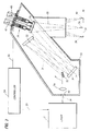
- the high speed, high power laser system 38 is best seen by now referring to Figure 2 wherein a similar but higher power industrial laser 11 is operably connected by means of a flexible connector 29 with a controller 24, which for purposes of example, could comprise a computerized numerical controller (cnc) or a programmable logic controller (plc) for a full range of control functions.
- the controller in turn connects with a scanner assembly 25 and servomotors 42,43 by means of a separate flexible connector 30 to control the orientation of the large reflecting mirror which serves as the scanning mirror 26.
- the laser beam 28 passes through an opening 54 in the support housing 55 and then through a negative (diverging) spherical lens 56.
- the cylindrically corrected, diverging beam 31 is reflected at a 45 degree angle by a first flat mirror 32.
- this mirror may be a phase retarding mirror which imparts circular polarization to a linearly polarized incoming beam.
- the continually diverging beam 31' is reflected by a second flat mirror 33 to a large spherical or parabolic mirror 34.
- the curvature of mirror 34, lens 56, their separation distances and the angle of incidence of the diverging beam 31'', with respect to the optical axis of mirror 34 are designed such that the converging beam 35 will reach a focal point 36 that is corrected for astigmatism.
- the position of the focal point 36 on the work surface 37 is determined by the position of the flat scanning mirror 26. As will be described below in greater detail, this laser focal point 36 may be manipulated rapidly to other positions 39, 40 on the work surface, as indicated in phantom, by programmed motion of the scanning mirror 26.
- the three dimensional operation of the scanning mirror 26 is achieved by the flexible drive system 65 within the scanner assembly 25 shown in an enlarged representation in Figure 3.
- the servomotors are connected by couplers 46 to corresponding lead screws 45 through a separate support plate 58.
- the lead screws 45 are connected to nuts 47, which are rigidly attached to couplings 48.
- the couplings are rigidly attached to one end of an inner spline 49.
- the inner splines are contained within corresponding outer splines 50, which permit linear translation of the inner splines but do not permit rotation or angular motion of the inner splines about their axes.
- the outer splines 50 are captured rigidly in support tubes 41, to which the servomotors 42,43 are attached.
- the opposite ends of the inner splines 49 are attached to hardened tooling balls 51, which rest in mirror locator seats 52, 53.
- a third locator seat 57 is shown in phantom and connects with a similar inner spline (not shown).
- Locator seat 52 is provided with a conical impression
- locator seat 53 is provided with a grooved impression
- locator seat 57 has a flat surface. Together these three seats, as positioned by the three tooling balls 51, fully define the rotational and lateral position of the scanning mirror 26.
- the scanning mirror 26 is held against the tooling balls 51 by the holding force applied by three pneumatic cylinders 15 which are attached via flexible couplings 44 to one side of the scanning mirror and via coupling 59 to the mounting plate 58 of the scanner assembly 25.
- Three such pneumatic cylinders are arranged in a circular pattern, interspaced between the support tubes 41 and act as constant force support springs to the scanning mirror 26.
- the effective spring force provided by the cylinders can be optimally controlled by varying the air pressure to the cylinders to counteract the gravitational and inertial forces acting on the scanning mirror during high speed operation.
- the servomotors 42,43 are individually rotated by means of the controller 24 according to predetermined position information. Each servomotor acts independently on its associated lead screw 45. When the lead screw rotates, it causes nut 47,coupling 48, inner spline 49 and tooling ball 51 to move in a straight line as defined by the fixed outer spline 50. The outer spline also prohibits any rotation or tilting of the associated inner spline.
- the force of the pneumatic cylinder 15 acts on the mirror 26 to keep the mirror locator seats 52, 53, 57 in contact with the tooling balls as they translate.
- the geometries of the mirror locator seats 52,53,57 are configured to provide the minimum non-redundant number of constraints necessary to position the scanning mirror 26.
- mirror locator seat 52 is conical, mirror locator seat 53 is grooved and mirror locator seat 57 is planar. Accordingly, there is a unique position of the three tooling balls 51 and the three associated servomotors for each position of the laser focal spot 36 on the work surface 37.
- a precisely controlled high power industrial laser system utilizing servomotors, a cnc or plc controller, beam delivery optics and a flexible scanner assembly for high speed three dimensional manipulation or a focused laser beam has herein been described.
- the system of the invention finds particular application in the fabric, automotive and stereolithographic fields.
Landscapes
- Physics & Mathematics (AREA)
- Optics & Photonics (AREA)
- Engineering & Computer Science (AREA)
- Plasma & Fusion (AREA)
- Mechanical Engineering (AREA)
- Chemical & Material Sciences (AREA)
- Manufacturing & Machinery (AREA)
- Materials Engineering (AREA)
- Laser Beam Processing (AREA)
- Mechanical Optical Scanning Systems (AREA)
- Lasers (AREA)
Applications Claiming Priority (2)
| Application Number | Priority Date | Filing Date | Title |
|---|---|---|---|
| US906600 | 1992-06-29 | ||
| US07/906,600 US5268554A (en) | 1992-06-29 | 1992-06-29 | Apparatus and system for positioning a laser beam |
Publications (2)
| Publication Number | Publication Date |
|---|---|
| EP0577358A1 true EP0577358A1 (fr) | 1994-01-05 |
| EP0577358B1 EP0577358B1 (fr) | 1996-12-27 |
Family
ID=25422700
Family Applications (1)
| Application Number | Title | Priority Date | Filing Date |
|---|---|---|---|
| EP93305014A Expired - Lifetime EP0577358B1 (fr) | 1992-06-29 | 1993-06-28 | Appareil et méthode pour positionner un rayon laser |
Country Status (6)
| Country | Link |
|---|---|
| US (1) | US5268554A (fr) |
| EP (1) | EP0577358B1 (fr) |
| JP (1) | JPH075385A (fr) |
| CA (1) | CA2096147C (fr) |
| DE (1) | DE69306865T2 (fr) |
| MX (1) | MX9303878A (fr) |
Cited By (3)
| Publication number | Priority date | Publication date | Assignee | Title |
|---|---|---|---|---|
| ES2113828A1 (es) * | 1995-07-04 | 1998-05-01 | Wernicke & Co Gmbh | Procedimiento para el pulimento asi como, dado el caso, para el taladro, el corte y la soldadura de lentes de gafas. |
| WO2001051244A1 (fr) * | 2000-01-13 | 2001-07-19 | Raylase Ag | Appareil et procede de ciblage |
| WO2006122804A1 (fr) * | 2005-05-20 | 2006-11-23 | Keysystech Gmbh | Dispositif de balayage pour un dispositif de soudage par laser de puissance comprenant un miroir de deviation qui peut pivoter autour de deux axes |
Families Citing this family (31)
| Publication number | Priority date | Publication date | Assignee | Title |
|---|---|---|---|---|
| US5381258A (en) * | 1994-03-14 | 1995-01-10 | Virtek Vision Intelligence Robotics Technologies Corporation | Laser projector for projecting an image onto a curvilinear surface |
| US5661667A (en) * | 1994-03-14 | 1997-08-26 | Virtek Vision Corp. | 3D imaging using a laser projector |
| DE19513354A1 (de) * | 1994-04-14 | 1995-12-14 | Zeiss Carl | Materialbearbeitungseinrichtung |
| EP0683007B1 (fr) * | 1994-04-14 | 1998-05-20 | Carl Zeiss | Dispositif d'usinage |
| US5632915A (en) * | 1994-08-29 | 1997-05-27 | Gerber Garment Technology, Inc. | Laser material processing apparatus and a work table therefor |
| US5674414A (en) * | 1994-11-11 | 1997-10-07 | Carl-Zeiss Stiftung | Method and apparatus of irradiating a surface of a workpiece with a plurality of beams |
| DE69600131T2 (de) * | 1995-04-19 | 1998-07-23 | Gerber Garment Technology Inc | Laserschneidgerät und Verfahren zum Schneiden von Flachmaterial |
| DE19519150A1 (de) * | 1995-05-30 | 1996-12-12 | Fraunhofer Ges Forschung | Laserstrahlgerät und Verfahren zur Bearbeitung von Werkstücken |
| US5837962A (en) * | 1996-07-15 | 1998-11-17 | Overbeck; James W. | Faster laser marker employing acousto-optic deflection |
| US6087619A (en) * | 1997-05-13 | 2000-07-11 | Fraunhofer Usa Resource Center | Dual intensity multi-beam welding system |
| DE19910880A1 (de) * | 1999-03-11 | 2000-09-14 | Deckel Maho Gmbh | Werkzeugmaschine für die Werkstückbearbeitung mit spanenden Werkzeugen und Laserstrahl |
| US6479790B1 (en) | 2000-01-31 | 2002-11-12 | General Electric Company | Dual laser shock peening |
| US6605799B2 (en) | 2000-05-25 | 2003-08-12 | Westar Photonics | Modulation of laser energy with a predefined pattern |
| DE10038309A1 (de) * | 2000-08-05 | 2002-02-14 | Abb Research Ltd | Verfahren und Vorrichtung zum Schweißen |
| US7947067B2 (en) * | 2004-02-04 | 2011-05-24 | Erchonia Corporation | Scanning treatment laser with sweep beam spot and universal carriage |
| US7922751B2 (en) * | 2004-02-04 | 2011-04-12 | Erchonia Corporation | Stand-alone scanning laser device |
| CA2453858A1 (fr) * | 2001-07-17 | 2003-01-30 | Sieb & Meyer Ag | Dispositif de reglage de miroir notamment pour des machines d'usinage par laser |
| WO2003046613A2 (fr) * | 2001-11-28 | 2003-06-05 | Overbeck James W | Microscopie a balayage, detection de fluorescence, et positionnement de faisceau laser |
| DE10217200A1 (de) * | 2002-04-18 | 2003-10-30 | Winter Pipeline Gmbh | Verfahren und Vorrichtung zur Materialbearbeitung mit Laserstrahlen |
| JP3708104B2 (ja) * | 2004-01-13 | 2005-10-19 | 浜松ホトニクス株式会社 | レーザ加工方法及びレーザ加工装置 |
| US20080125837A1 (en) * | 2004-02-06 | 2008-05-29 | Therapy Products, Inc. | Noninvasive method for site-specific fat reduction with catalyst |
| US7233424B2 (en) * | 2004-08-30 | 2007-06-19 | Dot Intellectual Properties, Llc | Steering assembly with electromagnetic actuators |
| CN100424540C (zh) * | 2004-09-14 | 2008-10-08 | 中国科学院安徽光学精密机械研究所 | 大口径光学潜望式激光雷达三维扫描装置 |
| US7233643B2 (en) * | 2005-05-20 | 2007-06-19 | Oxford Instruments Analytical Oy | Measurement apparatus and method for determining the material composition of a sample by combined X-ray fluorescence analysis and laser-induced breakdown spectroscopy |
| WO2007041460A2 (fr) * | 2005-10-03 | 2007-04-12 | Aradigm Corporation | Procede et systeme d'usinage laser |
| US20090132012A1 (en) * | 2007-11-16 | 2009-05-21 | Therapy Products, Inc. | Method for pretreating patient before surgery |
| US20100196497A1 (en) * | 2009-02-02 | 2010-08-05 | Therapy Products, Inc. | Method of Treating Tissue Using Platelet-Rich Plasma in Combination with Low-Level Laser Therapy |
| US8138487B2 (en) * | 2009-04-09 | 2012-03-20 | Cymer, Inc. | System, method and apparatus for droplet catcher for prevention of backsplash in a EUV generation chamber |
| US10549382B2 (en) * | 2016-05-04 | 2020-02-04 | Purdue Research Foundation | Laser-assisted micromachining systems and methods |
| US10654596B1 (en) | 2016-09-29 | 2020-05-19 | Northrop Grumman Systems Corporation | On-orbit thermal extractions of raw materials from space debris in support of additive manufacturing of new space elements on-orbit |
| DE102022123730A1 (de) * | 2022-09-16 | 2024-03-21 | TRUMPF Werkzeugmaschinen SE + Co. KG | Laserbearbeitung mit Scanneroptik |
Citations (6)
| Publication number | Priority date | Publication date | Assignee | Title |
|---|---|---|---|---|
| US4659900A (en) * | 1985-07-06 | 1987-04-21 | Prima Industrie S.P.A. | Laser cutting machine |
| US4664487A (en) * | 1985-09-30 | 1987-05-12 | Rockwell International Corporation | Laser mirror positioning apparatus |
| US4762994A (en) * | 1986-11-10 | 1988-08-09 | Ibm Corp. | Compact optical scanner driven by a resonant galvanometer |
| EP0345469A1 (fr) * | 1988-05-23 | 1989-12-13 | Westinghouse Electric Corporation | Système d'alignement et de transport d'un faisceau laser |
| US5011282A (en) * | 1989-11-16 | 1991-04-30 | Amada Company, Limited | Laser beam path alignment apparatus for laser processing machines |
| US5067086A (en) * | 1988-01-08 | 1991-11-19 | Fanuc, Ltd. | Three-dimensional shape machining laser device |
Family Cites Families (1)
| Publication number | Priority date | Publication date | Assignee | Title |
|---|---|---|---|---|
| US3514776A (en) * | 1968-05-27 | 1970-05-26 | United Aircraft Corp | Mirror device |
-
1992
- 1992-06-29 US US07/906,600 patent/US5268554A/en not_active Expired - Fee Related
-
1993
- 1993-05-13 CA CA002096147A patent/CA2096147C/fr not_active Expired - Fee Related
- 1993-06-28 MX MX9303878A patent/MX9303878A/es not_active IP Right Cessation
- 1993-06-28 DE DE69306865T patent/DE69306865T2/de not_active Expired - Fee Related
- 1993-06-28 EP EP93305014A patent/EP0577358B1/fr not_active Expired - Lifetime
- 1993-06-28 JP JP5157417A patent/JPH075385A/ja active Pending
Patent Citations (6)
| Publication number | Priority date | Publication date | Assignee | Title |
|---|---|---|---|---|
| US4659900A (en) * | 1985-07-06 | 1987-04-21 | Prima Industrie S.P.A. | Laser cutting machine |
| US4664487A (en) * | 1985-09-30 | 1987-05-12 | Rockwell International Corporation | Laser mirror positioning apparatus |
| US4762994A (en) * | 1986-11-10 | 1988-08-09 | Ibm Corp. | Compact optical scanner driven by a resonant galvanometer |
| US5067086A (en) * | 1988-01-08 | 1991-11-19 | Fanuc, Ltd. | Three-dimensional shape machining laser device |
| EP0345469A1 (fr) * | 1988-05-23 | 1989-12-13 | Westinghouse Electric Corporation | Système d'alignement et de transport d'un faisceau laser |
| US5011282A (en) * | 1989-11-16 | 1991-04-30 | Amada Company, Limited | Laser beam path alignment apparatus for laser processing machines |
Cited By (4)
| Publication number | Priority date | Publication date | Assignee | Title |
|---|---|---|---|---|
| ES2113828A1 (es) * | 1995-07-04 | 1998-05-01 | Wernicke & Co Gmbh | Procedimiento para el pulimento asi como, dado el caso, para el taladro, el corte y la soldadura de lentes de gafas. |
| WO2001051244A1 (fr) * | 2000-01-13 | 2001-07-19 | Raylase Ag | Appareil et procede de ciblage |
| US6763045B2 (en) | 2000-01-13 | 2004-07-13 | Raylase Ag | Apparatus for and method of targeting |
| WO2006122804A1 (fr) * | 2005-05-20 | 2006-11-23 | Keysystech Gmbh | Dispositif de balayage pour un dispositif de soudage par laser de puissance comprenant un miroir de deviation qui peut pivoter autour de deux axes |
Also Published As
| Publication number | Publication date |
|---|---|
| DE69306865T2 (de) | 1997-06-19 |
| DE69306865D1 (de) | 1997-02-06 |
| EP0577358B1 (fr) | 1996-12-27 |
| MX9303878A (es) | 1994-04-29 |
| US5268554A (en) | 1993-12-07 |
| CA2096147C (fr) | 2002-04-30 |
| JPH075385A (ja) | 1995-01-10 |
| CA2096147A1 (fr) | 1993-12-30 |
Similar Documents
| Publication | Publication Date | Title |
|---|---|---|
| CA2096147C (fr) | Appareil servant a positionner un rayon laser, et systeme connexe | |
| EP1228835B1 (fr) | Système et procédé de soudage laser à distance | |
| US4626999A (en) | Apparatus for controlled manipulation of laser focus point | |
| US4539462A (en) | Robotic laser beam delivery apparatus | |
| US4638143A (en) | Robot-laser system | |
| US20080259425A1 (en) | Scanner Head for a Laser Machining Device | |
| EP4161729B1 (fr) | Machine laser, machine laser et ensemble outil de détection d'alignement de faisceau laser, procédé d'alignement et d'étalonnage | |
| US4967053A (en) | Laser system | |
| JPS6250094A (ja) | レ−ザ光線による切断機械 | |
| JPH05285686A (ja) | レーザ加工装置用手首構造、およびそれを用いたレーザ加工方法 | |
| JPH05506104A (ja) | レーザービーム等の平行ビームを配送するための装置 | |
| US5038015A (en) | End effector for translating in a cartesian coordinate system | |
| KR100964680B1 (ko) | 다면체 레이저 가공 장치 및 방법 | |
| US5061834A (en) | End effector for translating in a cartesian coordinate system | |
| JP2662679B2 (ja) | 多関節形レーザ加工ロボット | |
| RU2283738C1 (ru) | Установка для лазерной обработки | |
| US20220088704A1 (en) | Multi-source laser head for laser engraving | |
| RU2064389C1 (ru) | Станок для обработки лазерным лучом | |
| NL193239C (nl) | Inrichting voor het uitvoeren van bewerkingen met behulp van een laserbundel. | |
| US6721241B1 (en) | Optical information system with motor controlled reflector means in a swivel arm | |
| JPH0247623A (ja) | レーザー光線用回転鏡装置 | |
| CN120985073A (zh) | 一种五轴联动式复杂曲面高效高精度加工装置及方法 | |
| JPS6376784A (ja) | レ−ザ加工機用の回転ヘツド | |
| JPH06677A (ja) | レ−ザ加工ヘッド | |
| JPH03151184A (ja) | レーザ加工装置の加工ヘッド |
Legal Events
| Date | Code | Title | Description |
|---|---|---|---|
| PUAI | Public reference made under article 153(3) epc to a published international application that has entered the european phase |
Free format text: ORIGINAL CODE: 0009012 |
|
| AK | Designated contracting states |
Kind code of ref document: A1 Designated state(s): CH DE FR GB IT LI |
|
| 17P | Request for examination filed |
Effective date: 19940630 |
|
| 17Q | First examination report despatched |
Effective date: 19950703 |
|
| GRAG | Despatch of communication of intention to grant |
Free format text: ORIGINAL CODE: EPIDOS AGRA |
|
| GRAH | Despatch of communication of intention to grant a patent |
Free format text: ORIGINAL CODE: EPIDOS IGRA |
|
| GRAH | Despatch of communication of intention to grant a patent |
Free format text: ORIGINAL CODE: EPIDOS IGRA |
|
| GRAA | (expected) grant |
Free format text: ORIGINAL CODE: 0009210 |
|
| AK | Designated contracting states |
Kind code of ref document: B1 Designated state(s): CH DE FR GB IT LI |
|
| REG | Reference to a national code |
Ref country code: CH Ref legal event code: NV Representative=s name: RITSCHER & SEIFERT PATENTANWAELTE VSP |
|
| ET | Fr: translation filed | ||
| REF | Corresponds to: |
Ref document number: 69306865 Country of ref document: DE Date of ref document: 19970206 |
|
| ITF | It: translation for a ep patent filed | ||
| PLBE | No opposition filed within time limit |
Free format text: ORIGINAL CODE: 0009261 |
|
| STAA | Information on the status of an ep patent application or granted ep patent |
Free format text: STATUS: NO OPPOSITION FILED WITHIN TIME LIMIT |
|
| 26N | No opposition filed | ||
| REG | Reference to a national code |
Ref country code: GB Ref legal event code: IF02 |
|
| PGFP | Annual fee paid to national office [announced via postgrant information from national office to epo] |
Ref country code: FR Payment date: 20040618 Year of fee payment: 12 |
|
| PGFP | Annual fee paid to national office [announced via postgrant information from national office to epo] |
Ref country code: CH Payment date: 20040621 Year of fee payment: 12 |
|
| PGFP | Annual fee paid to national office [announced via postgrant information from national office to epo] |
Ref country code: GB Payment date: 20040623 Year of fee payment: 12 |
|
| PGFP | Annual fee paid to national office [announced via postgrant information from national office to epo] |
Ref country code: DE Payment date: 20040802 Year of fee payment: 12 |
|
| PG25 | Lapsed in a contracting state [announced via postgrant information from national office to epo] |
Ref country code: IT Free format text: LAPSE BECAUSE OF NON-PAYMENT OF DUE FEES;WARNING: LAPSES OF ITALIAN PATENTS WITH EFFECTIVE DATE BEFORE 2007 MAY HAVE OCCURRED AT ANY TIME BEFORE 2007. THE CORRECT EFFECTIVE DATE MAY BE DIFFERENT FROM THE ONE RECORDED. Effective date: 20050628 Ref country code: GB Free format text: LAPSE BECAUSE OF NON-PAYMENT OF DUE FEES Effective date: 20050628 |
|
| PG25 | Lapsed in a contracting state [announced via postgrant information from national office to epo] |
Ref country code: LI Free format text: LAPSE BECAUSE OF NON-PAYMENT OF DUE FEES Effective date: 20050630 Ref country code: CH Free format text: LAPSE BECAUSE OF NON-PAYMENT OF DUE FEES Effective date: 20050630 |
|
| PG25 | Lapsed in a contracting state [announced via postgrant information from national office to epo] |
Ref country code: DE Free format text: LAPSE BECAUSE OF NON-PAYMENT OF DUE FEES Effective date: 20060103 |
|
| REG | Reference to a national code |
Ref country code: CH Ref legal event code: PL |
|
| PG25 | Lapsed in a contracting state [announced via postgrant information from national office to epo] |
Ref country code: FR Free format text: LAPSE BECAUSE OF NON-PAYMENT OF DUE FEES Effective date: 20060228 |
|
| GBPC | Gb: european patent ceased through non-payment of renewal fee |
Effective date: 20050628 |
|
| REG | Reference to a national code |
Ref country code: FR Ref legal event code: ST Effective date: 20060228 |