EP0578166A1 - Métier à tricoter circulaire - Google Patents
Métier à tricoter circulaire Download PDFInfo
- Publication number
- EP0578166A1 EP0578166A1 EP93110714A EP93110714A EP0578166A1 EP 0578166 A1 EP0578166 A1 EP 0578166A1 EP 93110714 A EP93110714 A EP 93110714A EP 93110714 A EP93110714 A EP 93110714A EP 0578166 A1 EP0578166 A1 EP 0578166A1
- Authority
- EP
- European Patent Office
- Prior art keywords
- coils
- coil
- rotor
- disposed
- hollow cylinder
- Prior art date
- Legal status (The legal status is an assumption and is not a legal conclusion. Google has not performed a legal analysis and makes no representation as to the accuracy of the status listed.)
- Withdrawn
Links
- 238000009940 knitting Methods 0.000 title claims abstract description 31
- 230000005284 excitation Effects 0.000 claims description 22
- 230000033001 locomotion Effects 0.000 claims description 19
- 238000010276 construction Methods 0.000 description 5
- 238000010586 diagram Methods 0.000 description 3
- XEEYBQQBJWHFJM-UHFFFAOYSA-N Iron Chemical group [Fe] XEEYBQQBJWHFJM-UHFFFAOYSA-N 0.000 description 2
- 239000004744 fabric Substances 0.000 description 2
- 238000012423 maintenance Methods 0.000 description 2
- 238000004804 winding Methods 0.000 description 2
- 206010046542 Urinary hesitation Diseases 0.000 description 1
- 230000001174 ascending effect Effects 0.000 description 1
- 238000001816 cooling Methods 0.000 description 1
- 238000001514 detection method Methods 0.000 description 1
- 238000004519 manufacturing process Methods 0.000 description 1
- 238000000034 method Methods 0.000 description 1
- 238000013024 troubleshooting Methods 0.000 description 1
Images


Classifications
-
- D—TEXTILES; PAPER
- D04—BRAIDING; LACE-MAKING; KNITTING; TRIMMINGS; NON-WOVEN FABRICS
- D04B—KNITTING
- D04B15/00—Details of, or auxiliary devices incorporated in, weft knitting machines, restricted to machines of this kind
- D04B15/32—Cam systems or assemblies for operating knitting instruments
Definitions
- the present invention relates to a circular knitting machine.
- the present invention provides a circular knitting machine which does not require knitting cams which lie at the base of the above-mentioned problems.
- the circular knitting machine claimed in claim 1 comprises a stationary hollow cylinder, a rotor disposed within said stationary cylinder and adapted to revolve coaxially therewith, a plurality of coils disposed on the internal circumferential surface of said stationary hollow cylinder, a plurality of sliders disposed in vertically slidable relation on the external circumferential surface of said rotor and adapted to slide vertically on excitation of said coils, a plurality of needles disposed on top of said respective sliders, a coil energizing means for exciting said plurality of coils, and a drive means for driving said rotor.
- the circular knitting machine claimed in claim 2 is a machine of claim 1 wherein said plurality of coils are disposed in the form of a grating as viewed by developing the internal circumferential surface of said stationary hollow cylinder, said coil energizing means energizes said coils disposed in the manner of a grating in a sequence from top to bottom along the rotational direction of said rotor to generate magnetic attraction forces to cause said sliders on the revolving rotor to be shifted upwards as they traverse said serially excited coils or said coil energizing means energizes said coils disposed in the manner of a grating in a sequence from top to bottom along the rotational direction of said rotor to generate magnetic attraction forces to thereby cause the sliders on said revolving rotor to be shifted downwards as they traverse the serially excited coils.
- the circular knitting machine claimed in claim 3 is a machine of claim 2 which further comprises a data input means for inputting circumferential direction data representing the circumferential position of said stationary hollow cylinder or rotor for driving the needles vertically and distance data representing the vertical distance of movement of the needles in said circumferential position, a coil excitation setting means for determining the coils to be excited among said plurality of coils according to the circumferential direction data and distance data input from said input means, and a coil excitation control means for controlling said coil energizing means to energize the coils designated by said coil excitation setting means.
- the plurality of coils disposed on the internal circumferential surface of the stationary hollow cylinder are energized by the coil energizing means.
- the rotor revolves in coaxial relation to said stationary hollow cylinder.
- the sliders disposed on the outer circumferential surface of the rotor are rotated together with the rotor as a unit and as any slider traverses the excited coil, it is shifted up or down by the magnetic attraction force of the coil, with the result that the needle mounted on top of the slider is driven up or down.
- the plurality of coils are disposed in the manner of a grating as viewed by developing the internal circumferential surface of said stationary hollow cylinder.
- said coil energizing means is actuated to energize the coils disposed in the manner of a grating in a sequence from bottom to top along the rotational direction of said rotor to generate magnetic attraction forces to thereby cause the slider on the revolving rotor to be raised by the magnetic force of the coil as it traverses the excited coil.
- said coil energizing means energizes said coils disposed in the manner of a grating in a sequence from top to bottom along the rotational direction of said rotor to generate magnetic attraction forces to thereby cause the slider on the revolving rotor to be lowered by the magnetic force of the coil as it traverses the excited coil.
- the input means is supplied with circumferential direction data representing the circumferential position of said stationary hollow cylinder or rotor for driving the needles vertically and distance data representing the vertical distance of movement of the needle in said circumstantial position.
- the coil excitation setting means determines the coils to be excited among said plurality of coils according to the circumferential direction data and distance data input from said input means.
- the coil excitaiton control means controls said coil energizing means to excite the coils designated by said coil excitation setting means.
- the coil setting means determines an excitation pattern, i.e. the pattern of coils to be excited, according to said needle motion data.
- the coil excitation control means controls the coil energizing means so that the coils will be excited in accordance with said excitation pattern.
- the circular knitting machine of the present invention employs the principle of a linear motor using coils and sliders and, therefore, has no mechanical structure.
- the motion of needles is not delimited by the cam configuration and, moreover, the machine is easy to maintain. Furthermore, the needle motion can be easily varied by merely changing the coil excitation pattern.
- the reference numeral 12 indicates a stationary hollow cylinder which is rigidly mounted on a base 13.
- the external circumferential surface of this stationary cylinder 12 is provided with a plurality of cooling fins 14 for dissipation of heat at predetermined intervals, while the internal circumferential surface of said stationary hollow cylinder 12 is provided with a plurality of coils 16.
- the construction of the coils 16 will be described in detail hereinafter.
- the reference numeral 18 indicates a rotor.
- the rotor 18 is disposed within said stationary hollow cylinder 12 in coaxially rotatable relation.
- the rotor 18 is provided with a timing pulley 20 at its lower end and is rotatable through a radial bearing 22 and a thrust bearing 24.
- the rotor 18 comprises a lower drum 18a and an upper drum 18b and the diameter of the upper drum 18b is smaller than that of the lower drum 18a.
- the rotor 18 is centrally formed with a cavity 26. As a yarn S supplied from the top of the rotor 18 is knitted into a circular fabric, it is accumulated in this cavity 26.
- the rotor 18 revolves as a timing pulley 20 is driven by a servo motor 46 (Fig. 2).
- a servo motor 46 Fig. 2
- the rotor 18 is forced, by the servo motor 46, to revolve within the stationary hollow cylinder 12.
- the reference numeral 28 indicates a plurality of sliders disposed at predetermined intervals on the external circumferential surface of the lower drum 18a.
- the sliders 28 are supported by pairs of linear guides 30, 30 in vertically movable relation.
- the reference numeral 34 indicates a plurality of needles disposed at predetermined intervals on the external circumferential surface of the upper drum 18b. Each of the needles 34 is operatively associated with the top end of the corresponding slider 28 by way of a link 32.
- the slider 28 and the needle 34 are each provided in units of, for example, 200 along the entire circumference.
- the number of sliders 28 should correspond to the number of needles 34 and may range, for example, from 80 to 200.
- the link 32 is vertically rotatable about a pivot 36 situated on top of the lower drum 18a so that as the slider 28 moves upwards, the link 32 turns to lower the needle 34.
- the upper surface of the lower drum 18a is provided with a plurality of grooves 100 arranged in radially equi-spaced relation. Disposed in each groove 100 is a link 32 extending in a substantially horizontal direction, and this link 32 is freely rotatable about a pivot 36 (cf. Figs. 15 and 16). Connected to an outward end 32a of the link 32 is the top end of the slider 28 which is disposed in vertical position. Connected to an inner end 32b of said link 32 is the lower end of the needle 34 which is disposed in vertical position. And as shown in Fig. 17, the outer end 32a of the link 32 is raised as the slider 28 rises, so that the inner end 32b of the link 32 is lowered according to the principle of leverage. As the inner end 32b of the link 32 descends, the needle 34 is also lowered. And as the slider 28 descends, the needle 34 is raised.
- each coil 16 comprises an iron core 38 projecting inwards from the internal circumferential surface of the stationary hollow cylinder 18 and a coil winding 40 disposed around said iron core 38. As a current flows to the coil winding 40, the coil 16 is excited.
- a plurality of coils 16 of the above construction are arranged longitudinally, viz. vertically, and transversely, viz. horizontally (in the direction of rotation), both at appropriate intervals (this arrangement of coils 16 is hereinafter referred to as "arranged in the form of a grating").
- this arrangement of coils 16 is hereinafter referred to as "arranged in the form of a grating").
- the coils 16 are arranged equi-spacedly in the direction of rotation.
- the number of coils 16 in the longitudinal direction may be about 24 and the number of coils 16 in the direction of rotation may be about 200. The greater the number of coils 16 in the longitudinal and rotational directions, the smoother is the rotation of the needles 34.
- a plurality of pairs of linear guides 30, 30 are disposed in the longitudinal direction on the external circumferential surface of the rotor 18.
- the slider 28 has a groove 29 on either side, by which the linear guide 30, 30 is engaged so that the slider 28 may move vertically with respect to the external circumferential surface of the rotor 18 (Fig. 5).
- the external surface of the slider 28 is roughened so that it may be more susceptible to the magnetic force of the coil 16.
- a linear motor is formed by the coil 16 and the slider 28.
- the gap L between the coil 16 and the slider 28 may be 0.5 mm to 1.5 mm (Fig. 6).
- the reference numeral 44 indicates a coil energizing unit for exciting said plurality of coils 16.
- the coil energizing unit 44 is adapted to individually excite said plurality of coils 16.
- the reference numeral 46 indicates a servo motor for driving the rotor 18 through said timing pulley 20.
- the reference numeral 48 indicates a driving circuit for driving the servo motor 46.
- the reference numeral 50 indicates a rotation detector, such as an encoder, for detecting the speed and angle of rotation of said servo motor 46.
- the rotation signal from the rotation detector 50 is fed to the driving means 48 for feedback control insuring a constant rotational speed of the servo motor 46.
- the reference numeral 52 indicates a converter for converting a pattern design image from a system such as a pattern design system into needle motions of the circular knitting machine 10.
- the converter 52 is provided with an external memory device such as a floppy disk and the pattern design data, such as that of a stocking, entered by the pattern design system and stored in the floppy disk, are fed from said external memory device to the converter 52.
- the converter 52 converts the data into the motion of needles 34 for circular knitting.
- the reference numeral 54 indicates a setting device for converting needle motion data from the converter 52 into the coil excitation pattern.
- the reference numeral 56 indicates a driver pattern controller for controlling the coil energizing device 44 according to the coil excitation pattern selected by the setting device 54.
- the converter 52 for converting the image of a stocking, for instance, from the pattern design system into motions of needles 34 can be a device well-known in the art.
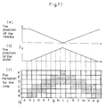
- Fig. 11 (a) shows the position of a needle 34.
- the vertical axis represents the vertical position of the needle 34 and the horizontal axis represents the position of the same needle 34 in the direction of rotation.
- the distance of vertical movement of the needle 34 is “the vertical distance” recited in claim 4.
- the position of the needle 34 in the direction of rotation on the horizontal axis is the "circumferential position" recited in claim 4.
- Fig. 11 (b) shows the position of the slider 28.
- the vertical axis represents the vertical position
- the horizontal axis represents the position of the slider 28 in the direction of rotation.
- Fig. 11 (c) shows the excitation pattern for the coils 16.
- the vertical axis represents the positions of coils 16 arranged in the vertical direction and the horizontal axis represents the positions of coils 16 in the direction of rotation.
- the coils 16 to be excited are specified by selecting A, B .... on the vertical axis and a, b .... on the horizontal axis.
- the coil 16 corresponding to the coordinates (A, a) can be selected by designating A on the vertical axis and a on the horizontal axis.
- the rotor 18 is driven and the excitation pattern for the coils 16 is controlled so that the slider 28 first moves upwards and, then, moves downwards.
- the coils 16 in the shaded blocks of Fig. 11 (c) are excited, for example in the manner of (A, b), (B, b) ... (E, j) ....
- the plurality of coils 16 are arranged in the form of a grating as viewed by developing the internal circumferential surface of the stationary hollow cylinder 18. Therefore, in order to shift the slider 28 upwards, the coils 16 are successively excited in an ascending series in the rotational direction of the rotor 18. In order to shift the slider 28 downwards, the coils 16 are successively excited in a descending series in the rotational direction of the rotor 18.
- the slider 28 is shifted upwards in response to excitation of coils 16 in the above manner. In order to lower the slides 28, the above excitation procedure is performed in a reverse order.
- one reference coil 16A and one reference slider 28A are previously established as shown in Fig. 4. Then, from the timing of the reference slider 28A traversing the reference coil 16A and the detection signal from the rotation detector 50, the setting device 54 keeps a constant tab on the geometric relation of coils 16 with sliders 28. Therefore, the relation between the coil excitation pattern and the action of the sliders 28 is defined on a 1:1 basis so that a fabric conforming to the pattern design can be successfully fabricated.
- the circular knitting machine 10 does not employ knitting cams for driving needles 34 but utilizes the principle of a linear motor, i.e. the combination of a plurality of coils 16 and a plurality of sliders 28, to achieve vertical motions of needles 34. In other words, there is no mechanical structure and, hence, the maintenance of the machine is facilitated.
- the motion of needles 34 can be easily modified by changing the coil excitation pattern only.
Landscapes
- Engineering & Computer Science (AREA)
- Textile Engineering (AREA)
- Knitting Machines (AREA)
Priority Applications (1)
| Application Number | Priority Date | Filing Date | Title |
|---|---|---|---|
| EP93110714A EP0578166A1 (fr) | 1992-07-08 | 1993-07-05 | Métier à tricoter circulaire |
Applications Claiming Priority (5)
| Application Number | Priority Date | Filing Date | Title |
|---|---|---|---|
| JP18076592 | 1992-07-08 | ||
| JP180765/92 | 1992-07-08 | ||
| EP92116672 | 1992-09-29 | ||
| EP92116672 | 1992-09-29 | ||
| EP93110714A EP0578166A1 (fr) | 1992-07-08 | 1993-07-05 | Métier à tricoter circulaire |
Publications (1)
| Publication Number | Publication Date |
|---|---|
| EP0578166A1 true EP0578166A1 (fr) | 1994-01-12 |
Family
ID=27234534
Family Applications (1)
| Application Number | Title | Priority Date | Filing Date |
|---|---|---|---|
| EP93110714A Withdrawn EP0578166A1 (fr) | 1992-07-08 | 1993-07-05 | Métier à tricoter circulaire |
Country Status (1)
| Country | Link |
|---|---|
| EP (1) | EP0578166A1 (fr) |
Cited By (5)
| Publication number | Priority date | Publication date | Assignee | Title |
|---|---|---|---|---|
| EP0717136A1 (fr) * | 1994-12-14 | 1996-06-19 | Tsudakoma Kogyo Kabushiki Kaisha | Appareil d'actionnement d'aiguilles d'un métier à tricoter |
| WO1998030743A1 (fr) * | 1997-01-08 | 1998-07-16 | Universal Maschinenfabrik Dr. Rudolf Schieber Gmbh & Co. Kg | Machine a tricoter |
| WO1998051847A1 (fr) * | 1997-05-15 | 1998-11-19 | Nanomotion Ltd. | Machine a tricoter |
| US6244076B1 (en) | 1997-05-15 | 2001-06-12 | Nanomotion Ltd. | Optical position monitor for knitting machines |
| DE102009033373A1 (de) * | 2009-07-16 | 2011-01-27 | H. Stoll Gmbh & Co. Kg | Strickmaschine |
Citations (3)
| Publication number | Priority date | Publication date | Assignee | Title |
|---|---|---|---|---|
| CH227781A (de) * | 1942-04-18 | 1943-07-15 | Lieberherr Rudolf | Strickmaschine. |
| DE2362631A1 (de) * | 1972-08-08 | 1975-06-19 | George Gati | Schlosslose strickmaschine mit einem nadelbett |
| EP0235987A1 (fr) * | 1986-02-13 | 1987-09-09 | Asahi Kasei Kogyo Kabushiki Kaisha | Procédé pour tricoter un tricot rectiligne, un métier à tricoter rectiligne et un tricot rectiligne tricoté par ce métier à tricoter |
-
1993
- 1993-07-05 EP EP93110714A patent/EP0578166A1/fr not_active Withdrawn
Patent Citations (3)
| Publication number | Priority date | Publication date | Assignee | Title |
|---|---|---|---|---|
| CH227781A (de) * | 1942-04-18 | 1943-07-15 | Lieberherr Rudolf | Strickmaschine. |
| DE2362631A1 (de) * | 1972-08-08 | 1975-06-19 | George Gati | Schlosslose strickmaschine mit einem nadelbett |
| EP0235987A1 (fr) * | 1986-02-13 | 1987-09-09 | Asahi Kasei Kogyo Kabushiki Kaisha | Procédé pour tricoter un tricot rectiligne, un métier à tricoter rectiligne et un tricot rectiligne tricoté par ce métier à tricoter |
Cited By (8)
| Publication number | Priority date | Publication date | Assignee | Title |
|---|---|---|---|---|
| EP0717136A1 (fr) * | 1994-12-14 | 1996-06-19 | Tsudakoma Kogyo Kabushiki Kaisha | Appareil d'actionnement d'aiguilles d'un métier à tricoter |
| US5588312A (en) * | 1994-12-14 | 1996-12-31 | Tsudakoma Kogyo Kabushiki Kaisha | Driving apparatus for needles of knitting machine |
| WO1998030743A1 (fr) * | 1997-01-08 | 1998-07-16 | Universal Maschinenfabrik Dr. Rudolf Schieber Gmbh & Co. Kg | Machine a tricoter |
| WO1998051847A1 (fr) * | 1997-05-15 | 1998-11-19 | Nanomotion Ltd. | Machine a tricoter |
| US6244076B1 (en) | 1997-05-15 | 2001-06-12 | Nanomotion Ltd. | Optical position monitor for knitting machines |
| US6367289B2 (en) | 1997-05-15 | 2002-04-09 | Nanomotion Ltd. | Actuator system for knitting machines |
| DE102009033373A1 (de) * | 2009-07-16 | 2011-01-27 | H. Stoll Gmbh & Co. Kg | Strickmaschine |
| DE102009033373B4 (de) * | 2009-07-16 | 2012-03-22 | H. Stoll Gmbh & Co. Kg | Strickmaschine |
Similar Documents
| Publication | Publication Date | Title |
|---|---|---|
| US3449928A (en) | Selector apparatus for circular knitting machines | |
| US4287808A (en) | Drive mechanism | |
| EP0578166A1 (fr) | Métier à tricoter circulaire | |
| CN1006474B (zh) | 平针织物的编织方法,一种横机 | |
| US20190022933A1 (en) | Intermittent excitation apparatus of 3d printer and method of operating the same | |
| US5282371A (en) | Circular knitting machine with magnetic actuated needle selection | |
| EP0485231A1 (fr) | Système d'actionnement d'une soupape électromagnétique | |
| US3872897A (en) | Process and device for the winding of coils for stators of electric machines | |
| EP0052852A1 (fr) | Appareil pour l'insertion de bobines | |
| EP1081082A2 (fr) | Dispositif et procédé de va-et-vient | |
| KR950002821B1 (ko) | 환편기 | |
| US3324685A (en) | Continuously driven thread transporting means | |
| US4719948A (en) | Method of and apparatus for winding coils | |
| JPH0673647A (ja) | 丸編機 | |
| CN217920798U (zh) | 一种络筒机用可提高纱线密度均匀缠绕的装置 | |
| US5895004A (en) | Coil winding apparatus for large diameter magnetic rings | |
| CN1089826C (zh) | 圆形针织机及其三角系统零件的设定机构 | |
| US4142357A (en) | Yarn guide for spinning or twisting machine | |
| JPH0241498B2 (fr) | ||
| SU929752A1 (ru) | Устройство дл наматывани пр жи на початок кольцевой текстильной машины (его варианты) | |
| JPH06235150A (ja) | 横編機 | |
| US5055753A (en) | Programmable servomotor coil winder | |
| EP0847458A1 (fr) | Machine a tricoter a aiguilles a tricoter radiales | |
| JPS5947539B2 (ja) | 多層多極連続巻線巻線装置 | |
| SU120579A1 (ru) | Полуавтоматический станок дл намотки корей электрических машин |
Legal Events
| Date | Code | Title | Description |
|---|---|---|---|
| PUAI | Public reference made under article 153(3) epc to a published international application that has entered the european phase |
Free format text: ORIGINAL CODE: 0009012 |
|
| AK | Designated contracting states |
Kind code of ref document: A1 Designated state(s): IT |
|
| 17P | Request for examination filed |
Effective date: 19940201 |
|
| STAA | Information on the status of an ep patent application or granted ep patent |
Free format text: STATUS: THE APPLICATION IS DEEMED TO BE WITHDRAWN |
|
| 18D | Application deemed to be withdrawn |
Effective date: 19960201 |