EP0578514B1 - Metallform-Wechselvorrichtung - Google Patents
Metallform-Wechselvorrichtung Download PDFInfo
- Publication number
- EP0578514B1 EP0578514B1 EP19930401189 EP93401189A EP0578514B1 EP 0578514 B1 EP0578514 B1 EP 0578514B1 EP 19930401189 EP19930401189 EP 19930401189 EP 93401189 A EP93401189 A EP 93401189A EP 0578514 B1 EP0578514 B1 EP 0578514B1
- Authority
- EP
- European Patent Office
- Prior art keywords
- metal mould
- hook
- advancing
- stand
- retreating member
- Prior art date
- Legal status (The legal status is an assumption and is not a legal conclusion. Google has not performed a legal analysis and makes no representation as to the accuracy of the status listed.)
- Expired - Lifetime
Links
Images


Classifications
-
- B—PERFORMING OPERATIONS; TRANSPORTING
- B23—MACHINE TOOLS; METAL-WORKING NOT OTHERWISE PROVIDED FOR
- B23Q—DETAILS, COMPONENTS, OR ACCESSORIES FOR MACHINE TOOLS, e.g. ARRANGEMENTS FOR COPYING OR CONTROLLING; MACHINE TOOLS IN GENERAL CHARACTERISED BY THE CONSTRUCTION OF PARTICULAR DETAILS OR COMPONENTS; COMBINATIONS OR ASSOCIATIONS OF METAL-WORKING MACHINES, NOT DIRECTED TO A PARTICULAR RESULT
- B23Q3/00—Devices holding, supporting, or positioning work or tools, of a kind normally removable from the machine
- B23Q3/155—Arrangements for automatic insertion or removal of tools, e.g. combined with manual handling
-
- B—PERFORMING OPERATIONS; TRANSPORTING
- B29—WORKING OF PLASTICS; WORKING OF SUBSTANCES IN A PLASTIC STATE IN GENERAL
- B29C—SHAPING OR JOINING OF PLASTICS; SHAPING OF MATERIAL IN A PLASTIC STATE, NOT OTHERWISE PROVIDED FOR; AFTER-TREATMENT OF THE SHAPED PRODUCTS, e.g. REPAIRING
- B29C45/00—Injection moulding, i.e. forcing the required volume of moulding material through a nozzle into a closed mould; Apparatus therefor
- B29C45/17—Component parts, details or accessories; Auxiliary operations
- B29C45/1756—Handling of moulds or mould parts, e.g. mould exchanging means
-
- B—PERFORMING OPERATIONS; TRANSPORTING
- B30—PRESSES
- B30B—PRESSES IN GENERAL
- B30B15/00—Details of, or accessories for, presses; Auxiliary measures in connection with pressing
- B30B15/02—Dies; Inserts therefor; Mounting thereof; Moulds
- B30B15/028—Loading or unloading of dies, platens or press rams
-
- Y—GENERAL TAGGING OF NEW TECHNOLOGICAL DEVELOPMENTS; GENERAL TAGGING OF CROSS-SECTIONAL TECHNOLOGIES SPANNING OVER SEVERAL SECTIONS OF THE IPC; TECHNICAL SUBJECTS COVERED BY FORMER USPC CROSS-REFERENCE ART COLLECTIONS [XRACs] AND DIGESTS
- Y10—TECHNICAL SUBJECTS COVERED BY FORMER USPC
- Y10S—TECHNICAL SUBJECTS COVERED BY FORMER USPC CROSS-REFERENCE ART COLLECTIONS [XRACs] AND DIGESTS
- Y10S100/00—Presses
- Y10S100/918—Bolster and die
-
- Y—GENERAL TAGGING OF NEW TECHNOLOGICAL DEVELOPMENTS; GENERAL TAGGING OF CROSS-SECTIONAL TECHNOLOGIES SPANNING OVER SEVERAL SECTIONS OF THE IPC; TECHNICAL SUBJECTS COVERED BY FORMER USPC CROSS-REFERENCE ART COLLECTIONS [XRACs] AND DIGESTS
- Y10—TECHNICAL SUBJECTS COVERED BY FORMER USPC
- Y10T—TECHNICAL SUBJECTS COVERED BY FORMER US CLASSIFICATION
- Y10T483/00—Tool changing
- Y10T483/17—Tool changing including machine tool or component
- Y10T483/1729—Reciprocating tool machine tool [e.g., broaching machine, shaping machine, etc.]
-
- Y—GENERAL TAGGING OF NEW TECHNOLOGICAL DEVELOPMENTS; GENERAL TAGGING OF CROSS-SECTIONAL TECHNOLOGIES SPANNING OVER SEVERAL SECTIONS OF THE IPC; TECHNICAL SUBJECTS COVERED BY FORMER USPC CROSS-REFERENCE ART COLLECTIONS [XRACs] AND DIGESTS
- Y10—TECHNICAL SUBJECTS COVERED BY FORMER USPC
- Y10T—TECHNICAL SUBJECTS COVERED BY FORMER US CLASSIFICATION
- Y10T83/00—Cutting
- Y10T83/869—Means to drive or to guide tool
- Y10T83/8748—Tool displaceable to inactive position [e.g., for work loading]
Definitions
- the present invention relates to a metal mould replacing apparatus which serves to replace a metal mould for use in a moulding machine such as an injection moulding machine and a press machine.
- the conventional metal mould replacing apparatus disclosed therein comprises a metal mould replacing stand of the carriage type disposed behind an injection moulding machine, an advancing/retreating member provided movably in the fore and rear direction along a guide rail placed on the carriage type replacing stand and a hook vertically swingably supported by the advancing/retreating member so that an engaging portion formed in the front swingable portion of the hook can engage with an engaged portion of a rear portion of a metal mould from below.
- the above-mentioned conventional replacing apparatus is adapted to swing the hook below the engaged portion of the metal mould, even when the metal mould sways at the time of placement onto the carriage type replacing stand by a crane and the like, the engaged portion can be prevented from colliding against the hook. Therefore, it becomes unnecessary to provide a space behind the replacing stand for retreating the advancing/retreating member and the hook, so that it becomes possible to decrease a width dimension of the replacing stand in the fore and rear direction by that omitted retreat space.
- the conventional replacing apparatus has such an advantage that an area occupied at the time of running of the carriage type replacing stand can be reduced so that a building site of a moulding factory employing such an improved replacing stand can be reduced.
- the above-mentioned object is achieved by a metal mould replacing apparatus as defined in claim 1.
- the present invention is constructed as follows, for example as shown in Figs. 1 through 5.
- a metal mould replacing stand 3 is disposed at the rear R of a moulding machine 1 and has a metal mould moving path 14 provided thereon in the fore and rear direction.
- a push/pull drive device 19 disposed in the rear portion of the metal mould replacing stand 3
- a rear portion of a transmission member 21 is connected as well as a front portion of the transmission member 21 is connected to an advancing/retreating member 22.
- a guide rail 23 which accommodates the transmission member 21 and the advancing/retreating member 22 is placed along said metal mould moving path 14.
- a hook 28 is supported vertically swingably by the advancing/retreating member 22 and has an engaging portion 30 formed in the rear swingable portion thereof so as to engage with an engaged portion 34 of a rear portion of a metal mould 7 from below.
- the present invention functions as follows.
- the advancing/retreating member 22 is made to retreat toward the rear side R by means of the push/pull drive device 19 through the transmission member 21.
- the engaging portion 30 formed in the rear portion of the hook 28 approaches the engaged portion 34 provided in the rear portion of the metal mould 7 and then the engaging portion 30 engages with the engaged portion 34 from below.
- an upper surface 28a of the hook 28 is formed by a rearward ascending inclined surface
- the following advantages can be obtained.
- the hook 28 at the retreat position is advanced toward the metal mould 7 placed within the moulding machine 1
- firstly a midway portion of the hook upper surface 28a in the fore and rear direction is brought into contact with the lower end of the engaged portion 34 of the metal mould 7 and then the hook 28 is made to swing downward automatically by a reaction force exerted from the engaged portion 34.
- the downward swung hook 28 is made to swing upward by means of a spring force and the like, the engaging portion 30 thereof engages with the engaged portion 34 of the mould 7 automatically. Accordingly, the construction for making the hook 28 engage with the metal mould 7 can be simplified.
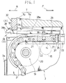
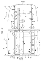
- Figs. 1 through 5 show a first embodiment of a metal mould replacing apparatus.
- the right sides of Figs. 1 through 3 are defined as the foreside F and the left sides thereof are defined as the rear side R.
- a pair of rails 2, 2 are placed at the rear R of an injection moulding machine 1 employed herein as a moulding machine, and a metal mould replacing stand 3 of the carriage type is movable along these rails 2, 2.
- the injection moulding machine 1 is so constructed that a metal mould 7 can be mounted between a fixed plate 5 and a movable plate 6.
- the metal mould 7 comprises a metal mould body portion 7a and a pair of plate portions 7b fixedly secured to the opposite sides thereof.
- the symbol 9 designates a tie rod, the symbol 10 does a hydraulic clamp for fixing the metal mould, the symbol 11 does a roller inside the plates and the symbol 12 does a pre-roller.
- a metal mould moving path 14 is provided in the upper portion of the metal mould replacing stand 3 so as to extend in the fore and rear direction (the direction along the arrows F, R ).
- This moving path 14 comprises many short rollers 15 and many long rollers 16.
- An electric push/pull drive device 19 is disposed in the rear portion of the replacing stand 3.
- a rear portion of a chain transmission member 21 meshes with a sprocket wheel 20 of the drive device 19 while a front portion of the transmission member 21 is connected to an advancing/retreating member 22.
- a first guide rail 23 for guiding the transmission member 21 and the advancing/retreating member 22 in the fore and rear direction is placed between both those rollers 15, 16.
- a second guide rail 24 is placed in the injection moulding machine 1 so as to align with the first guide rail 23.
- This guide rail 24 is disposed at a midway level between the tie rod 9 and the metal mould body portion 7a.
- the respective guide rails 23, 24 comprise a pair of rail members 25, 25 having C-shaped cross-sections and facing to each other.
- the sprocket wheel 20, the transmission member 21 and the guide rollers 27, 27 for the advancing/retreating member 22 are interposed between both the rail members 25, 25.
- a front portion of a hook 28 is supported vertically swingably by the front portion of the advancing/retreating member 22 through a pivot pin 29.
- An upper surface 28a of the hook 28 comprises a rearward ascending inclined surface.
- a concave engaging portion 30 is formed in the rear swingable portion of the hook 28 so as to face upward.
- a thin plate 32 is fixedly secured to the rear surface of the plate portion 7b of the metal mould 7 by means of a plurality of bolts 33.
- a convex engaged portion 34 is provided in the lower portion of the plate 32.
- the hook 28 is adapted to be advanced to an engagement position X ( refer to a figure depicted by the solid line ) on the upper side by means of a spring 36 and to be retreated to an engagement cancelled position Y ( refer to a figure depicted by the alternate long and two short dashes line ) on the lower side when a pin 37 supported at the front portion of the advancing/retreating member 22 is raised by means of an engagement cancelling cylinder ( to be later explained ).
- the metal mould replacing apparatus having the above-mentioned construction is utilized as follows.
- the operation for bringing the metal mould 7 into the injection moulding machine 1 is carried out by the following procedures. Firstly, the piston rod 40 is made to retreat downward. Then, the sprocket wheel 20 is made to rotate clockwise in Fig. 1 so as to advance the advancing/retreating member 22 toward the foreside F along the first guide rail 23 and the second guide rail 24 in order and to move the metal mould 7 toward the foreside F.
- a limit switch (not illustrated ) detects that arrival so that the rotation of the sprocket wheel 20 is stopped. After that, the metal mould 7 is fixed by means of the hydraulic clamp 10.
- the hook 28 is made to change over to the engagement cancelled position Y by means of an engagement cancelling cylinder 42 ( refer to Fig. 3 ) provided in the second guide rail 24, through the pin 37 ( refer to Fig. 1 ).
- an engagement cancelling cylinder 42 refer to Fig. 3
- the advancing/retreating member 22 is made to retreat toward the rear side R and to return to the rear portion of the replacing stand 3.
- the operation for bringing out the metal mould 7 in the injection moulding machine 1 onto the replacing stand 3 is carried out by the following procedures.
- the advancing/retreating member 22 located in the rear portion of the replacing stand 3 is made to advance toward the foreside F along the first guide rail 23 and the second guide rail 24, the upper surface 28a of the hook 28 is brought into contact with the bottom surface of the engaged portion 34 in accompany of the advancement of the advancing/retreating member 22 and then the hook 28 is made to swing downward against the spring 36 by means of a reaction force acting onto the upper surface 28a from the engaged portion 34.
- the hook 28 is made to swing upward by means of the spring 36, so that the engaging portion 30 engages with the engaged portion 34. After that, the advancing/retreating member 22 is made to retreat toward the rear side R so as to bring out the metal mould 7.
- the advancing/retreating member 22 since the advancing/retreating member 22 is disposed in front F of the engaging portion 30, it becomes unnecessary to rearward project the first guide rail 23 which accommodates the advancing/retreating member 22 and accordingly it becomes also unnecessary to project the push/pull drive device 19 rearward. Thereby, it becomes possible to shorten a distance from the engaging portion 30 to the rear surface 3a of the metal mould replacing stand 3 and to decrease the width dimension W of the replacing stand 3 in the fore and rear direction by that shortened portion.
- Fig. 6 and Figs. 7 and 8 show a second embodiment and a third embodiment of the present invention respectively.
- component members having the same constructions as those of the above-mentioned first embodiment are designated by the same symbols in principle.
- the metal mould replacing stand 3 of the carriage type is disposed between two fore and rear injection moulding machines 1a, 1b so as to be movable in the left and the right directions ( in the vertical directions in Fig. 6 ).
- Both a first guide rail 46 and short rollers 47 for the first injection moulding machine 1a and both a first guide rail 48 and short rollers 49 for the second injection moulding machine 1b are arranged respectively at the left and at the right outside common long rollers 45 disposed in the replacing stand 3.
- Pre-roller devices 51, 51 and second guide rails 52, 52 are provided in the respective injection moulding machines 1a, 1b.
- a pair of advancing/retreating members 22, 22 are so disposed as to face each other in the end portions of the first guide rails 46, 48 facing each other.
- the symbol 28 designates the hook, and the symbol 19 does the push/pull drive device.
- the width dimension W of the replacing stand 3 in the fore and rear direction can be further decreased by those shortened portions.
- the metal mould replacing apparatus according to the present invention is applied to a press machine.
- the first guide rail 23 provided in the metal mould replacing stand 3 of the carriage type is disposed at a lower level below the upper surface of the replacing stand 3.
- the advancing/retreating member 22 and the hook 28 are accommodated by the first guide rail 23.
- the symbol 60 designates a transfer roller and the metal mould moving path 14 is defined by the upper surfaces of the rollers 60.
- a concave groove 62 is formed in a bolster 61a of a press machine 61 so as to extend in the fore and rear direction and the second guide rail 24 is inserted into the concave groove 62.
- a lower portion of a plate 64 fixedly secured to a rear surface of a metal mould 63 is made to project into the concave groove 62.
- the symbol 65 designates a pre-roller device and the symbol 66 does a transfer roller device.
- the metal mould replacing stand 3 may be of the stationary type instead of the carriage type.
- the metal mould moving path 14 of the replacing stand 3 may comprise a flat surface instead of the rollers.
- the transmission member 21 may comprise a belt, a wire and the like instead of the chain.
- the engaging portion 30 of the hook 28 may be formed in a convex configuration and the engaged portion 34 of the metal mould 7 may be formed in a concave configuration.
Landscapes
- Engineering & Computer Science (AREA)
- Mechanical Engineering (AREA)
- Manufacturing & Machinery (AREA)
- Moulds For Moulding Plastics Or The Like (AREA)
- Mounting, Exchange, And Manufacturing Of Dies (AREA)
Claims (4)
- Metallformwechselvorrichtung, mit:einer Metallformwechseleinheit (3);einer Metallform (7) mit einem in Eingriff bringbaren Abschnitt 34, wobei die auf der Vorrichtung angeordnete Form eine Fläche dazwischen bildet;einem Metallformbewegungsweg (14) in der Metallformwechselvorrichtung (3), der sich bis zu einer Formmaschine (1) nach vorne und hinten (F, R) erstreckt;einer Zug/Stoßantriebsvorrichtung (19), die von der Metallformwechselvorrichtung (3) gestützt ist;einem vor/rücklaufenden Element (22) mit vorderem und hinterem Ende, die vorne und hinten entsprechen;einem Zug/Stoßübertragungselement (21), das betrieblich mit der Antriebsvorrichtung (19) verbunden ist, wobei das Übertragungselement ein mit dem hinteren Ende des vor/rücklaufenden Teils verbundenes Vorderende besitzt;einer Führungsschiene (23), die von der Metallformwechselvorrichtung (3) entlang des Bewegungsweges (14) zur Führung des Übertragungselements (21) und des vor/rücklaufenden Elementes (22) getragen wird; undeinem Haken (28) mit einem vorderen Abschnitt und einem hinteren Teil, ausgerichtet in Richtung des Formbewegungswegs, wobei der Haken senkrecht schwenkbar durch das vor/rücklaufende Element (22) gelagert und mit einem Greifabschnitt (30) versehen ist, der mit dem in Eingriff bringbaren Abschnitt (34) von unten in Eingriff kommen kann,dadurch gekennzeichnet, daß der vordere Abschnitt des Hakens (28) vertikal drehbar durch das vordere Ende des vor/rücklaufenden Elementes (22) gelagert und das hintere Teil des Hakens mit dem Greifabschnitt 30) versehen ist.
- Metallformwechselvorrichtung nach Anspruch 1, wobei eine Platte (32) fest am hinteren Teil der Metallform (7) befestigt ist und der in Eingriff bringbare Abschnitt (34) im unteren Teil der Platte (32) vorgesehen ist.
- Metallformwechselvorrichtung nach Anspruch 2, wobei eine obere Oberfläche (28a) des Hakens (28) eine nach hinten ansteigende abgeschrägte Oberfläche besitzt.
- Metallformwechselvorrichtung nach Anspruch 2 oder Anspruch 3, wobei eine Nockenoberfläche (28b), die zur Kontaktierung des in Eingriff bringbaren Abschnitts (34) von unten eingerichtet ist, im hinteren Abschnitt des Hakens (28) gebildet ist, um abzufallen.
Applications Claiming Priority (2)
| Application Number | Priority Date | Filing Date | Title |
|---|---|---|---|
| JP174968/92 | 1992-06-08 | ||
| JP17496892A JP2964287B2 (ja) | 1992-06-08 | 1992-06-08 | 金型交換装置 |
Publications (2)
| Publication Number | Publication Date |
|---|---|
| EP0578514A1 EP0578514A1 (de) | 1994-01-12 |
| EP0578514B1 true EP0578514B1 (de) | 1997-11-26 |
Family
ID=15987890
Family Applications (1)
| Application Number | Title | Priority Date | Filing Date |
|---|---|---|---|
| EP19930401189 Expired - Lifetime EP0578514B1 (de) | 1992-06-08 | 1993-05-10 | Metallform-Wechselvorrichtung |
Country Status (5)
| Country | Link |
|---|---|
| US (1) | US5364328A (de) |
| EP (1) | EP0578514B1 (de) |
| JP (1) | JP2964287B2 (de) |
| KR (1) | KR100250401B1 (de) |
| DE (1) | DE69315387T2 (de) |
Families Citing this family (8)
| Publication number | Priority date | Publication date | Assignee | Title |
|---|---|---|---|---|
| KR200465371Y1 (ko) | 2010-11-24 | 2013-02-14 | 조규형 | 금형 교환장치 |
| CN102166830A (zh) * | 2011-01-17 | 2011-08-31 | 合肥合锻机床股份有限公司 | 一种改进的换模小车 |
| CN107074328A (zh) * | 2014-10-07 | 2017-08-18 | 菱重维斯塔斯海上风力有限公司 | 从风轮机发电机平台取出设备部分的装置和方法及填充所述平台上的燃料储罐的方法 |
| PL3347131T3 (pl) * | 2015-09-07 | 2020-09-21 | Mbe Coal & Minerals Technology Gmbh | Sposób i urządzenie do demontażu rolek prasy rolkowej |
| AT518520B1 (de) * | 2016-05-25 | 2017-11-15 | Trumpf Maschinen Austria Gmbh & Co Kg | Werkzeug-Speichersystem, Fertigungsanlage sowie Verfahren zum Manipulieren mit einem derartigen Werkzeug-Speichersystem |
| CN106181081A (zh) * | 2016-08-26 | 2016-12-07 | 江苏亚威机床股份有限公司 | 一种激光切割机升降工作台交换装置 |
| US12076895B2 (en) | 2019-05-17 | 2024-09-03 | Canon Virginia, Inc. | Mold and molding system |
| CN114378618B (zh) * | 2022-01-21 | 2024-03-29 | 广东智目科技有限公司 | 一种数控机床刀库 |
Family Cites Families (6)
| Publication number | Priority date | Publication date | Assignee | Title |
|---|---|---|---|---|
| FR1591599A (de) * | 1968-07-23 | 1970-05-04 | ||
| JPS58119926U (ja) * | 1982-02-04 | 1983-08-16 | 相生精機株式会社 | 金型を用いる加工機械の金型交換装置 |
| US4597709A (en) * | 1983-08-01 | 1986-07-01 | Aioi Seiki K.K. | Transferring device for dies and the like |
| FR2583025B1 (fr) * | 1985-06-05 | 1990-11-23 | Telemecanique Electrique | Dispositif de transfert de palettes entre une ligne principale et une unite de derivation accolee a cette ligne principale. |
| US5063648A (en) * | 1988-11-29 | 1991-11-12 | Kabushiki Kaisha Kosmek | Apparatus and method for replacing working-object of processing machine |
| US5217727A (en) * | 1991-03-29 | 1993-06-08 | Kabushiki Kaisha Kosmek | Apparatus for placing a mold |
-
1992
- 1992-06-08 JP JP17496892A patent/JP2964287B2/ja not_active Expired - Fee Related
-
1993
- 1993-03-27 KR KR1019930004899A patent/KR100250401B1/ko not_active Expired - Fee Related
- 1993-05-10 DE DE69315387T patent/DE69315387T2/de not_active Expired - Fee Related
- 1993-05-10 EP EP19930401189 patent/EP0578514B1/de not_active Expired - Lifetime
- 1993-05-18 US US08/062,756 patent/US5364328A/en not_active Expired - Fee Related
Also Published As
| Publication number | Publication date |
|---|---|
| EP0578514A1 (de) | 1994-01-12 |
| DE69315387D1 (de) | 1998-01-08 |
| KR940000173A (ko) | 1994-01-03 |
| JPH05337948A (ja) | 1993-12-21 |
| JP2964287B2 (ja) | 1999-10-18 |
| DE69315387T2 (de) | 1998-03-19 |
| US5364328A (en) | 1994-11-15 |
| KR100250401B1 (ko) | 2000-04-01 |
Similar Documents
| Publication | Publication Date | Title |
|---|---|---|
| US4597709A (en) | Transferring device for dies and the like | |
| US5364328A (en) | Metal mould replacing apparatus | |
| EP0371710B1 (de) | Einrichtung und Verfahren zum Auswechseln der Werkstücke an Bearbeitungsmaschinen | |
| US4073237A (en) | Power and free conveyor with pusher disengaging means operable on curved sections of conveyor track | |
| JPH0318562B2 (de) | ||
| JPH0645030Y2 (ja) | ウインドレギユレータ装置 | |
| EP0506558B1 (de) | Gerät zum Positionieren einer Gussform | |
| JP3648782B2 (ja) | フロントフェンダー成形型のワーク押え装置 | |
| JPH0839374A (ja) | 搬送装置 | |
| KR920001419Y1 (ko) | 차량 정비용 승강기의 차륜고정장치 | |
| US4725212A (en) | Tire curing press and loader | |
| US5526753A (en) | Storage apparatus for a storage conveyor | |
| US5507233A (en) | Power and free conveyor utilizing a pair of swinging hooks | |
| JPH09271860A (ja) | プレス機械の金型交換台車装置 | |
| GB2102368A (en) | Reciprocating conveyer having gripper engaging plates to be conveyed | |
| JPH0546408U (ja) | 治工具、金型等の押し引き装置 | |
| CN214360058U (zh) | 装配式构件转移装置 | |
| JP2594868B2 (ja) | ブラシロールのロールチョック前後方向自動拘束装置 | |
| JPH0335487Y2 (de) | ||
| CN218839428U (zh) | 一种平移式过跨车防撞装置 | |
| JPS6347449Y2 (de) | ||
| JP2578730Y2 (ja) | 金型置き装置 | |
| JPH0613785Y2 (ja) | 等速継手のボールの欠品検出装置 | |
| JPS603008Y2 (ja) | 吊下げ搬送装置 | |
| US5293818A (en) | Transfer device, such as a printer device |
Legal Events
| Date | Code | Title | Description |
|---|---|---|---|
| PUAI | Public reference made under article 153(3) epc to a published international application that has entered the european phase |
Free format text: ORIGINAL CODE: 0009012 |
|
| AK | Designated contracting states |
Kind code of ref document: A1 Designated state(s): DE FR GB IT |
|
| 17P | Request for examination filed |
Effective date: 19940208 |
|
| 17Q | First examination report despatched |
Effective date: 19951128 |
|
| GRAG | Despatch of communication of intention to grant |
Free format text: ORIGINAL CODE: EPIDOS AGRA |
|
| GRAH | Despatch of communication of intention to grant a patent |
Free format text: ORIGINAL CODE: EPIDOS IGRA |
|
| GRAH | Despatch of communication of intention to grant a patent |
Free format text: ORIGINAL CODE: EPIDOS IGRA |
|
| GRAA | (expected) grant |
Free format text: ORIGINAL CODE: 0009210 |
|
| AK | Designated contracting states |
Kind code of ref document: B1 Designated state(s): DE FR GB IT |
|
| PG25 | Lapsed in a contracting state [announced via postgrant information from national office to epo] |
Ref country code: IT Free format text: LAPSE BECAUSE OF FAILURE TO SUBMIT A TRANSLATION OF THE DESCRIPTION OR TO PAY THE FEE WITHIN THE PRESCRIBED TIME-LIMIT;WARNING: LAPSES OF ITALIAN PATENTS WITH EFFECTIVE DATE BEFORE 2007 MAY HAVE OCCURRED AT ANY TIME BEFORE 2007. THE CORRECT EFFECTIVE DATE MAY BE DIFFERENT FROM THE ONE RECORDED. Effective date: 19971126 Ref country code: FR Free format text: LAPSE BECAUSE OF FAILURE TO SUBMIT A TRANSLATION OF THE DESCRIPTION OR TO PAY THE FEE WITHIN THE PRESCRIBED TIME-LIMIT Effective date: 19971126 |
|
| REF | Corresponds to: |
Ref document number: 69315387 Country of ref document: DE Date of ref document: 19980108 |
|
| EN | Fr: translation not filed | ||
| PG25 | Lapsed in a contracting state [announced via postgrant information from national office to epo] |
Ref country code: GB Free format text: LAPSE BECAUSE OF NON-PAYMENT OF DUE FEES Effective date: 19980510 |
|
| PGFP | Annual fee paid to national office [announced via postgrant information from national office to epo] |
Ref country code: DE Payment date: 19980522 Year of fee payment: 6 |
|
| PLBE | No opposition filed within time limit |
Free format text: ORIGINAL CODE: 0009261 |
|
| STAA | Information on the status of an ep patent application or granted ep patent |
Free format text: STATUS: NO OPPOSITION FILED WITHIN TIME LIMIT |
|
| 26N | No opposition filed | ||
| GBPC | Gb: european patent ceased through non-payment of renewal fee |
Effective date: 19980510 |
|
| PG25 | Lapsed in a contracting state [announced via postgrant information from national office to epo] |
Ref country code: DE Free format text: LAPSE BECAUSE OF NON-PAYMENT OF DUE FEES Effective date: 20000301 |