EP0578517A1 - Verfahren zum Behandeln von schmelzflüsssigem Metall während eines Giessvorganges unter Verwendung eines Filters sowie dazu verwendete Filter - Google Patents
Verfahren zum Behandeln von schmelzflüsssigem Metall während eines Giessvorganges unter Verwendung eines Filters sowie dazu verwendete Filter Download PDFInfo
- Publication number
- EP0578517A1 EP0578517A1 EP93401373A EP93401373A EP0578517A1 EP 0578517 A1 EP0578517 A1 EP 0578517A1 EP 93401373 A EP93401373 A EP 93401373A EP 93401373 A EP93401373 A EP 93401373A EP 0578517 A1 EP0578517 A1 EP 0578517A1
- Authority
- EP
- European Patent Office
- Prior art keywords
- filter
- plates
- filter according
- metal
- cavity
- Prior art date
- Legal status (The legal status is an assumption and is not a legal conclusion. Google has not performed a legal analysis and makes no representation as to the accuracy of the status listed.)
- Granted
Links
Images


Classifications
-
- C—CHEMISTRY; METALLURGY
- C21—METALLURGY OF IRON
- C21C—PROCESSING OF PIG-IRON, e.g. REFINING, MANUFACTURE OF WROUGHT-IRON OR STEEL; TREATMENT IN MOLTEN STATE OF FERROUS ALLOYS
- C21C7/00—Treating molten ferrous alloys, e.g. steel, not covered by groups C21C1/00 - C21C5/00
-
- B—PERFORMING OPERATIONS; TRANSPORTING
- B01—PHYSICAL OR CHEMICAL PROCESSES OR APPARATUS IN GENERAL
- B01D—SEPARATION
- B01D29/00—Filters with filtering elements stationary during filtration, e.g. pressure or suction filters, not covered by groups B01D24/00 - B01D27/00; Filtering elements therefor
- B01D29/01—Filters with filtering elements stationary during filtration, e.g. pressure or suction filters, not covered by groups B01D24/00 - B01D27/00; Filtering elements therefor with flat filtering elements
- B01D29/03—Filters with filtering elements stationary during filtration, e.g. pressure or suction filters, not covered by groups B01D24/00 - B01D27/00; Filtering elements therefor with flat filtering elements self-supporting
-
- B—PERFORMING OPERATIONS; TRANSPORTING
- B01—PHYSICAL OR CHEMICAL PROCESSES OR APPARATUS IN GENERAL
- B01D—SEPARATION
- B01D29/00—Filters with filtering elements stationary during filtration, e.g. pressure or suction filters, not covered by groups B01D24/00 - B01D27/00; Filtering elements therefor
- B01D29/50—Filters with filtering elements stationary during filtration, e.g. pressure or suction filters, not covered by groups B01D24/00 - B01D27/00; Filtering elements therefor with multiple filtering elements, characterised by their mutual disposition
- B01D29/56—Filters with filtering elements stationary during filtration, e.g. pressure or suction filters, not covered by groups B01D24/00 - B01D27/00; Filtering elements therefor with multiple filtering elements, characterised by their mutual disposition in series connection
-
- B—PERFORMING OPERATIONS; TRANSPORTING
- B22—CASTING; POWDER METALLURGY
- B22C—FOUNDRY MOULDING
- B22C9/00—Moulds or cores; Moulding processes
- B22C9/08—Features with respect to supply of molten metal, e.g. ingates, circular gates, skim gates
- B22C9/086—Filters
-
- B—PERFORMING OPERATIONS; TRANSPORTING
- B22—CASTING; POWDER METALLURGY
- B22D—CASTING OF METALS; CASTING OF OTHER SUBSTANCES BY THE SAME PROCESSES OR DEVICES
- B22D1/00—Treatment of fused masses in the ladle or the supply runners before casting
- B22D1/007—Treatment of the fused masses in the supply runners
-
- B—PERFORMING OPERATIONS; TRANSPORTING
- B01—PHYSICAL OR CHEMICAL PROCESSES OR APPARATUS IN GENERAL
- B01D—SEPARATION
- B01D2201/00—Details relating to filtering apparatus
- B01D2201/18—Filters characterised by the openings or pores
-
- C—CHEMISTRY; METALLURGY
- C21—METALLURGY OF IRON
- C21C—PROCESSING OF PIG-IRON, e.g. REFINING, MANUFACTURE OF WROUGHT-IRON OR STEEL; TREATMENT IN MOLTEN STATE OF FERROUS ALLOYS
- C21C1/00—Refining of pig-iron; Cast iron
- C21C1/10—Making spheroidal graphite cast-iron
Definitions
- the present invention relates to a method for treating molten metal during a mold casting operation with the interposition of a filter, this method comprising the step of placing a material for treating said molten metal before the casting of molten metal. a point on the channel adapted to guide said metal to the filter.
- the invention also relates to a filter for implementing the method according to the invention.
- the treatment agents are simply placed in the channels for the passage of molten metal, which is tedious.
- the destructible sachets are expelled from the place where they have been deposited and are pushed upstream into the funnel into which the metal is poured. in fusion. There is then a loss of unused processing material and scrap castings whose metal is insufficiently treated. Furthermore, the molten metal does not come fully into contact with the treatment material, and the metal poured into the mold risks being heterogeneous.
- the object of the present invention is to remedy the drawbacks of known methods, and to propose a method of the aforementioned type making it possible to ensure that all of the cast molten metal is treated as regularly and as homogeneously as possible, and that the material is fully used to treat said metal.
- the object of the present invention is also to propose a filter for the implementation of said method.
- the method of the aforementioned type is characterized in that a filter for molten metal is used comprising a series of at least two plates of refractory mineral material in contact with each other by their periphery and defining between one or more cavities, these plates each comprising a series of holes allowing the passage and filtration of the liquid metal, and in that the treatment material is introduced into at least one of the cavities before putting the filter in place in the mold.
- the metal cast according to the method of the invention has a distribution of the treatment product and a treatment homogeneity greater than that obtained with the known methods.
- the filter targeted by the latter for the implementation of the aforementioned method according to the first aspect of the invention comprises a series of at least two plates of refractory mineral matter in contact with each other. the others by their periphery and defining between them one or more cavities, these plates each comprising a series of holes allowing the passage and filtration of the liquid metal.
- this filter is characterized in that at least one of the cavities contains a material for the treatment of said metal.
- the filter comprises at least two plates assembled along their periphery by a seal, the cavity formed between the two plates is filled with powdery treatment material, and the holes in the plates are closed by a film made of a material capable of melting, carbonizing or calcining on contact with the liquid metal to be treated, disposed on the inside or on the outside of each plate.
- the treatment material can thus be easily maintained by such a film insulated in a sealed manner from atmospheric humidity and remain perfectly dry, which allows storage without disadvantage of prefabricated filters.
- Filters are used to remove from the liquid metal any solid inclusion, for example of metal oxide, capable of affecting the quality of the metal which is poured into a container such as an ingot mold or a mold.
- the filter is characterized in that the treatment material is a material inoculating with respect to the liquid metal in the form of plate which may include one or more holes for the passage of liquid metal.
- This inoculating material improves the characteristics of the metal.
- This inoculating material thus makes it possible to significantly increase the efficiency of the filter by barrier effect. Furthermore, the cavities of the filter plates form receptacles which are particularly suitable for receiving the inoculating material, so that the use of this material does not imply any modification of the filter.
- At least the face of said plate adjacent to the bottom of the cavity comprises a series of recesses.
- said inoculating material is in the form of spaced bars extending over substantially the entire length and width of a cavity.
- At least one of the cavities of said plates is filled with a filtering material.
- This filter material consisting for example of refractory fibers further improves the efficiency of filtration.
- the inoculating material is preferably chosen among the following compounds: iron alloys, magnesium and magnesium compounds, calcium and its compounds, lithium compounds, strontium compounds and barium, silicon, zirconium, aluminum, rare earths, graphite and carbon compounds.
- the process targeted by the invention for treating molten metal during a mold casting operation with the interposition of a filter 1, 1a, 1b, 1c, 1d, 1e comprises the step which consists in: place before the casting of the molten metal a material 12, 22, 23, 24 for treating said metal at a point in the channel suitable for guiding said metal up to said filter.
- this method is characterized in that a filter 1, 1a, 1b, 1c, 1d, 1e, for liquid metal is used, comprising a series of at least two plates 2, 2a, 2b, made of mineral material refractory in contact with each other by their periphery and defining between them one or more cavities 4, 5, 6, these plates 2, 2a, 2b, each comprising a series of holes 3, 3a, 3b, allowing passage and filtration of the liquid metal, and in that the treatment material 12, 22, 23, 24 is introduced into at least one of the cavities 4, 5, 6, before installing the filter 1, 1a, 1b, 1c, 1d, 1e, in a mold (not shown), such as a cylindrical sleeve.
- a filter 1, 1a, 1b, 1c, 1d, 1e for liquid metal is used, comprising a series of at least two plates 2, 2a, 2b, made of mineral material refractory in contact with each other by their periphery and defining between them one or more cavities 4, 5, 6, these plates 2, 2
- the treatment material 12, 22, 23, 24 is chosen from desulfurizing, thermogenic, inoculating, spheroidizing, recarburizing, refining, modifying products and addition alloys.
- the weight of the treatment material 12, 22, 23, 24 can vary between 0.001% and about 1% of the weight of the liquid metal, depending on the nature of the treatment that it is desired to apply.
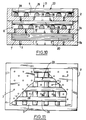
- the filter 1a shown in Figure 1 has three plates 2, 2a, 2b. Plates 2 and 2a have each a peripheral edge 11 projecting adapted to come into contact with the adjacent plate, 2a, 2b, corresponding which is thus kept at a distance to provide a cavity, respectively 4, 5.
- the plate 2b does not have such a rim, which would increase unnecessarily the height of the filter 1.
- the upper plate which is normally placed on the upstream side, is pierced with holes 3, 3a, 3b, of different diameters increasing in this order.
- the plates 2a, 2b also have holes of equal or different diameters.
- the holes in the intermediate plate 2a are staggered relative to the holes in the end plates 2 and 2b.
- the holes 3, 3a, 3b may have sections other than circular.
- the plates 2, 2a, 2b are in known manner made of a refractory ceramic mineral material, for example silica, and are capable of withstanding the temperature of the cast metal without deformation.
- the filter 1 shown in Figure 2 has a plate 2 having holes 3 of substantially the same diameter.
- the filter 1b shown in FIG. 3 consists of two plates 2a, the peripheral edges 11 of which are adjacent and joined to one another by a bonding 10.
- the heights of the flanges 11 are shown to be identical but could be different.
- the two plates define a cavity 6.
- the filter for liquid metal comprises three plates 2, 2a, 2b made of refractory material, in contact with each other, by their periphery and defining between them several cavities 5, 6, 7.
- These plates 2, 2a, 2b, include each a series of holes 3, allowing the passage and filtration of the liquid metal which passes through the filter in the direction of arrow D.
- At least one of the cavities 4, 5, 6 of the filter 1, 1a, 1b, 1c, 1d contains a material for the treatment of molten metal to treat.
- the treatment material 12 is in powder form and is retained by a film 13 of a material capable of melting, carbonizing or calcining on contact with the liquid metal to be treated.
- the particle size of the pulverulent material is chosen according to the treatment conditions that are desired.
- the film 13 of a material capable of melting, carbonizing or calcining on contact with the metal to be treated is for example an aluminum sheet or paper or a plastic film, or a composite sheet.
- the treatment material 12 is contained in sachets 8, 8a, 8b, produced with said film 13 and placed in said cavity 4, 5, 6.
- the cavities 4 and 5 of FIG. 1 each contain a sachet, respectively 8, 8a, which partially or almost completely fills the corresponding cavity 4, 5.
- These sachets 8, 8a can be identical or have different capacities.
- the cavity 6 in FIG. 3 contains a bag 8b arranged, by way of example, eccentrically in said cavity 6.
- the cavity 6 formed between the two plates 2a is filled with material 12 for powder treatment, and the holes 3 in the plates 2a are closed by a film 13 of the aforementioned type disposed on the inner face or on the outer face of each plate 2a.
- a film 13 is fixed, for example glued, on the inner face of the upper plate.
- Another film 13 is fixed to the outer face of the lower plate, the holes 3 being filled with treatment material 12.
- the films 13 are fixed on the interior faces of the plates in the left half-view and on the exterior faces of these plates in the right half-view.
- the latter case corresponds to the maximum volume of treatment material 12 contained in the filter 1c.
- the powder treatment material 12 is in compressed or sintered form, and is in the form of plates 14a, 14b or bars.
- the dimensions of the plates 14a, 14b or bars are less than or equal to the internal dimensions of the cavity 6, so that these plates or bars can be movable inside the cavity 6 from the start of the casting under the action of turbulence generated by the arrival of molten metal in the cavity 6.
- a plate 14a of hexagonal outline has been shown in the left half-views and in the right half-views a plate 14b of annular shape.
- Such plates 14a, 14b are for example compressed with a binder such as stearate or the like; it is also possible to agglomerate under high pressure the treatment material 12 prepared for example in crystallized form.
- the plate 14a has a central hole 15 for the passage of the metal. It could include other holes of various shapes and dimensions.
- the treatment materials can be desulfurization agents, for example magnesium and / or calcium carbide, and / or be thermogenic agents, for example calcium carbide, and / or be inoculating and / or post-inoculating agents, and / or spheroidizing agents, for example magnesium and / or rare earths and / or ferrosilicomagnesium, and / or agents of addition alloys, for example alloys of molybdenum, boron, silicon, ferrosilicon, manganese, chromium, titanium, ferroaluminium, with silicomischmetal, recarburising agents, for example based on carbon or graphite, fluxes to modify the structure of the metal, such as sodium, phosphorus, boron, titanium, strontium salts, etc.
- desulfurization agents for example magnesium and / or calcium carbide
- thermogenic agents for example calcium carbide
- inoculating and / or post-inoculating agents and / or spheroid
- FIGS. 8 to 13 illustrate other embodiments of the invention in which the treatment material is a material 22, 23, 24 having inoculating properties with respect to the liquid metal.
- the cavities 5, 6 each contain an inoculating material 22.
- the inoculating material 22 is in the form of a plate comprising holes 25 for the passage of liquid metal, said plate extending over substantially the entire length and width of a cavity 5 or 6.
- each plate 22 adjacent to the bottom of the cavity 5 or 6 comprises a series of recesses 26 formed by a series of parallel dihedrons.
- the other face of the plate 22 also has recesses 27. It can also be seen in FIGS. 8 and 9 that the holes 25 in the plate 22 of inoculating material have a larger section than that holes 3 of the refractory plates 2, 2a, 2b.
- liquid metal steel or liquid iron
- the filter shown in Figure 8 When the liquid metal (steel or liquid iron) passes through the filter shown in Figure 8, it enters first in contact with the upper surface of the plate 22 of inoculating material, passes through the latter through the holes 25, then fills the recesses 26 present on the underside of the plate 22 and then flows through the filtration holes 3 of plate 2.
- the metal fills the recesses 26, which makes it possible to obtain a large contact surface between the liquid metal and the inoculating material which promotes the metal processing reaction.
- the presence of the inoculating material 22 in the filter makes it possible, in combination with the filtration holes 3, to improve the characteristics of the metal more effectively than by a simple filtration operation.
- the inoculating material 23 is in the form of spaced bars 28, 29 extending over substantially the entire length and width of the cavities 5 and 6 of the refractory plates 2, 2a.
- the bars 28, 29 are arranged in two superimposed and crossed layers, as shown in particular in FIG. 11.
- the liquid metal licks the surface of the bars 28, 29 then accumulates at the bottom of the cavities 5, 6 before flowing down through the holes 3.
- This embodiment also makes it possible to produce a large contact surface between the liquid metal and the inoculating material, thereby improving the yield of the inoculant.
- the face of the plate made of inoculating material 24 adjacent to the bottom of the cavity 5 of the refractory plate 2 has a recess 30 delimited by a peripheral rim 31 which rests on the bottom of the cavity 5.
- This plate 24 has holes 32 for the passage of liquid metal.
- the holes 32 of the plate 24 of inoculating material have a larger section than that of the holes 3 of the plate 2. Therefore, the liquid metal which is poured on the plate 24 passes through the holes 32 and then fills the recess 30 before flowing through the openings 3 in the plate 2.
- the liquid metal is in contact with a large part of the surface of the inoculating material 24, which allows a more effective inoculation action.
- the inoculating material is in the form of a plate 2c with holes 3c of identical shape to that of the plates of refractory material 2, 2b and occupying the place of one of these.
- At least one of the cavities of the plates 2, 2a, 2b made of refractory material is filled with a filtering material 20, for example made of refractory fibers.
- this filter material 20 is arranged in a cavity 7 located (see FIGS. 8 and 10), downstream of a cavity 5 or 6, containing an inoculating material 22 or 23 relative to the direction D of the passage of the liquid metal.
- This filter material 20 adds its own efficiency to further increase the performance of the filter according to the invention.
- the inoculating material is chosen from the following compounds: iron alloy (for example Fe-Si alloy), magnesium and magnesium compounds, calcium and its compounds, lithium compounds, strontium compounds and compounds of barium, silicon, zirconium, aluminum, rare earths, graphite and carbon.
- the compressed or sintered plates 14a, 14b can be replaced by solid molded plates.
Landscapes
- Chemical & Material Sciences (AREA)
- Engineering & Computer Science (AREA)
- Chemical Kinetics & Catalysis (AREA)
- Mechanical Engineering (AREA)
- Materials Engineering (AREA)
- Metallurgy (AREA)
- Organic Chemistry (AREA)
- Manufacture And Refinement Of Metals (AREA)
- Casting Support Devices, Ladles, And Melt Control Thereby (AREA)
- Filtering Materials (AREA)
Applications Claiming Priority (6)
| Application Number | Priority Date | Filing Date | Title |
|---|---|---|---|
| LU88124A LU88124A1 (fr) | 1992-05-29 | 1992-05-29 | Filtre pour metal liquide |
| LU88124 | 1992-05-29 | ||
| FR9213039 | 1992-10-30 | ||
| FR9213039A FR2697444B1 (fr) | 1992-10-30 | 1992-10-30 | Filtre pour métal liquide à inoculant. |
| FR9300062A FR2691654B1 (fr) | 1992-05-29 | 1993-01-06 | Procédé pour traiter du métal en fusion dans une opération de coulée avec interposition d'un filtre, et filtre pour la mise en Óoeuvre de ce procédé. |
| FR9300062 | 1993-01-06 |
Publications (2)
| Publication Number | Publication Date |
|---|---|
| EP0578517A1 true EP0578517A1 (de) | 1994-01-12 |
| EP0578517B1 EP0578517B1 (de) | 1998-11-11 |
Family
ID=27252674
Family Applications (1)
| Application Number | Title | Priority Date | Filing Date |
|---|---|---|---|
| EP93401373A Expired - Lifetime EP0578517B1 (de) | 1992-05-29 | 1993-05-28 | Verfahren zum Behandeln von schmelzflüsssigem Metall während eines Giessvorganges unter Verwendung eines Filters sowie dazu verwendete Filter |
Country Status (5)
| Country | Link |
|---|---|
| EP (1) | EP0578517B1 (de) |
| JP (1) | JPH06108170A (de) |
| CA (1) | CA2097261C (de) |
| DE (1) | DE69322006T2 (de) |
| ES (1) | ES2126637T3 (de) |
Cited By (3)
| Publication number | Priority date | Publication date | Assignee | Title |
|---|---|---|---|---|
| FR2774611A1 (fr) * | 1998-02-11 | 1999-08-13 | Daussan & Co | Dispositif pour filtrer et traiter du metal en fusion |
| WO1999067045A1 (fr) * | 1998-06-25 | 1999-12-29 | Daussan & Compagnie | Procede pour preparer un moule de coulee |
| WO2008001034A1 (en) * | 2006-06-30 | 2008-01-03 | Kassim Juma | Filter device for molten metal filtration |
Families Citing this family (2)
| Publication number | Priority date | Publication date | Assignee | Title |
|---|---|---|---|---|
| EP1369190A1 (de) | 2002-06-03 | 2003-12-10 | Carbon Application Technology Ltd. | Filteranordnung für die Filtration von Metallschmelzen |
| DE102018201577B4 (de) * | 2017-02-03 | 2020-02-06 | Technische Universität Bergakademie Freiberg | Verfahren zur Herstellung eines Metallschmelze-Hybrid-Filters und keramischer Metallschmelze-Hybrid-Filter |
Citations (7)
| Publication number | Priority date | Publication date | Assignee | Title |
|---|---|---|---|---|
| US3658115A (en) * | 1970-11-30 | 1972-04-25 | Gen Motors Corp | Method of inoculating nodular cast iron |
| DE2608282A1 (de) * | 1976-02-28 | 1977-09-08 | Baur Eduard Dr Ing | Vorrichtung zum impfen und/oder legieren von metallischen schmelzen zum herstellen von gusstuecken |
| EP0195211A2 (de) * | 1985-03-14 | 1986-09-24 | E. Hofmann & Söhne oHG | Vorrichtung zum Filtern von metallischen Schmelzen |
| JPS62185859A (ja) * | 1986-02-10 | 1987-08-14 | Kubota Ltd | 型内接種用反応容器 |
| EP0234825A1 (de) * | 1986-02-25 | 1987-09-02 | Foseco International Limited | Giessen von flüssigen Eisenmetallen und deren Giessformen |
| EP0234979A1 (de) * | 1986-01-23 | 1987-09-02 | Daussan Et Compagnie | Feuerfester Filter |
| EP0249897A1 (de) * | 1986-06-11 | 1987-12-23 | O.E.T.-METALCONSULT S.r.l. | Verfahren zum Entgasen, Feinen oder Filtern von flüssigen Metallen und Legierungen, sowie die entsprechende Vorrichtung |
-
1993
- 1993-05-28 DE DE69322006T patent/DE69322006T2/de not_active Expired - Fee Related
- 1993-05-28 ES ES93401373T patent/ES2126637T3/es not_active Expired - Lifetime
- 1993-05-28 CA CA002097261A patent/CA2097261C/en not_active Expired - Fee Related
- 1993-05-28 EP EP93401373A patent/EP0578517B1/de not_active Expired - Lifetime
- 1993-05-31 JP JP5149797A patent/JPH06108170A/ja active Pending
Patent Citations (7)
| Publication number | Priority date | Publication date | Assignee | Title |
|---|---|---|---|---|
| US3658115A (en) * | 1970-11-30 | 1972-04-25 | Gen Motors Corp | Method of inoculating nodular cast iron |
| DE2608282A1 (de) * | 1976-02-28 | 1977-09-08 | Baur Eduard Dr Ing | Vorrichtung zum impfen und/oder legieren von metallischen schmelzen zum herstellen von gusstuecken |
| EP0195211A2 (de) * | 1985-03-14 | 1986-09-24 | E. Hofmann & Söhne oHG | Vorrichtung zum Filtern von metallischen Schmelzen |
| EP0234979A1 (de) * | 1986-01-23 | 1987-09-02 | Daussan Et Compagnie | Feuerfester Filter |
| JPS62185859A (ja) * | 1986-02-10 | 1987-08-14 | Kubota Ltd | 型内接種用反応容器 |
| EP0234825A1 (de) * | 1986-02-25 | 1987-09-02 | Foseco International Limited | Giessen von flüssigen Eisenmetallen und deren Giessformen |
| EP0249897A1 (de) * | 1986-06-11 | 1987-12-23 | O.E.T.-METALCONSULT S.r.l. | Verfahren zum Entgasen, Feinen oder Filtern von flüssigen Metallen und Legierungen, sowie die entsprechende Vorrichtung |
Non-Patent Citations (1)
| Title |
|---|
| PATENT ABSTRACTS OF JAPAN vol. 12, no. 37 (C - 473) 4 February 1988 (1988-02-04) * |
Cited By (7)
| Publication number | Priority date | Publication date | Assignee | Title |
|---|---|---|---|---|
| FR2774611A1 (fr) * | 1998-02-11 | 1999-08-13 | Daussan & Co | Dispositif pour filtrer et traiter du metal en fusion |
| EP0936007A1 (de) * | 1998-02-11 | 1999-08-18 | Daussan Et Compagnie | Vorrichtung zum Filtern und Behandeln von flüssigen Metallen |
| US6216768B1 (en) | 1998-02-11 | 2001-04-17 | Daussan Et Compagnie | Device for filtering and treating molten metal |
| CN1067441C (zh) * | 1998-02-11 | 2001-06-20 | 多森公司 | 过滤和处理熔融金属用的装置 |
| WO1999067045A1 (fr) * | 1998-06-25 | 1999-12-29 | Daussan & Compagnie | Procede pour preparer un moule de coulee |
| US6540005B1 (en) | 1998-06-25 | 2003-04-01 | Daussan & Compagnie | Method for preparing a casting mould |
| WO2008001034A1 (en) * | 2006-06-30 | 2008-01-03 | Kassim Juma | Filter device for molten metal filtration |
Also Published As
| Publication number | Publication date |
|---|---|
| CA2097261C (en) | 2001-07-24 |
| JPH06108170A (ja) | 1994-04-19 |
| CA2097261A1 (en) | 1993-11-30 |
| ES2126637T3 (es) | 1999-04-01 |
| DE69322006D1 (de) | 1998-12-17 |
| EP0578517B1 (de) | 1998-11-11 |
| DE69322006T2 (de) | 1999-06-10 |
Similar Documents
| Publication | Publication Date | Title |
|---|---|---|
| EP0057651B1 (de) | Verfahren zum schnellen Erstarren und Abkühlen durch Stranggiessen von geschmolzenen Materialien auf der Basis von Metalloxiden | |
| FR2626508A1 (fr) | Moule de coulee de metaux, equipe d'un manchon contenant un filtre | |
| CA2052899C (fr) | Procede pour la realisation de pieces a surface antiabrasion | |
| BE1000818A3 (fr) | Ajutage pour verser du metal fondu. | |
| EP2627824B1 (de) | Verfahren und vorrichtung zum aluminothermischen schweissen von schienen | |
| EP0578517A1 (de) | Verfahren zum Behandeln von schmelzflüsssigem Metall während eines Giessvorganges unter Verwendung eines Filters sowie dazu verwendete Filter | |
| US5690161A (en) | Process for treating molten metal during a casting operation using a filter and filter for implementing the process | |
| EP1091818B1 (de) | Verfahren zum präparieren einer giessform | |
| JP4801077B2 (ja) | チェーンソー用のリムスプロケット | |
| EP2397245B1 (de) | Schichteinheit, Modell, Herstellungsverfahren dieses Modells sowie Herstellungsverfahren eines Werkstücks aus diesem Modell | |
| FR2552351A1 (fr) | Procedes et moules a revetement interieur pour la coulee centrifuge | |
| FR2691654A1 (fr) | Procédé pour traiter du métal en fusion dans une opération de coulée avec interposition d'un filtre, et filtre pour la mise en Óoeuvre de ce procédé. | |
| FR2774611A1 (fr) | Dispositif pour filtrer et traiter du metal en fusion | |
| EP1305116B1 (de) | Schlagleiste für eine vertikale schleudermühle und herstellungsverfahren | |
| EP0242347A2 (de) | Vorrichtung zum Giessen einer flüssig-festen Mischung | |
| EP0112790B1 (de) | Verfahren zum GieBen eines Bremsrotors | |
| EP0907463B1 (de) | Schleifwerkzeug und verfahren zur herstellung desselben | |
| FR2697444A1 (fr) | Filtre pour métal liquide à inoculant. | |
| WO2002060618A1 (fr) | Procede de traitement et de coulee d"alliages oxydables | |
| FR2459834A1 (fr) | Procede et moule pour la fabrication de pieces de fonderie en fontes de fer-carbone a graphite spheroidal ou compact | |
| EP1099499B1 (de) | Verfahren zur Beschickung mit Giessmaterial bei Gussstücken mit Einsatz | |
| FR2658745A1 (fr) | Procede et dispositif de moulage d'un alliage metallique. | |
| FR2648373A1 (fr) | Pot de fonderie | |
| FR2736283A1 (fr) | Broyeur a axe vertical | |
| BE711632A (de) |
Legal Events
| Date | Code | Title | Description |
|---|---|---|---|
| PUAI | Public reference made under article 153(3) epc to a published international application that has entered the european phase |
Free format text: ORIGINAL CODE: 0009012 |
|
| 17P | Request for examination filed |
Effective date: 19930609 |
|
| AK | Designated contracting states |
Kind code of ref document: A1 Designated state(s): BE DE ES GB IT LU |
|
| 17Q | First examination report despatched |
Effective date: 19961001 |
|
| GRAG | Despatch of communication of intention to grant |
Free format text: ORIGINAL CODE: EPIDOS AGRA |
|
| GRAG | Despatch of communication of intention to grant |
Free format text: ORIGINAL CODE: EPIDOS AGRA |
|
| GRAG | Despatch of communication of intention to grant |
Free format text: ORIGINAL CODE: EPIDOS AGRA |
|
| GRAH | Despatch of communication of intention to grant a patent |
Free format text: ORIGINAL CODE: EPIDOS IGRA |
|
| GRAH | Despatch of communication of intention to grant a patent |
Free format text: ORIGINAL CODE: EPIDOS IGRA |
|
| GRAA | (expected) grant |
Free format text: ORIGINAL CODE: 0009210 |
|
| AK | Designated contracting states |
Kind code of ref document: B1 Designated state(s): BE DE ES GB IT LU |
|
| REF | Corresponds to: |
Ref document number: 69322006 Country of ref document: DE Date of ref document: 19981217 |
|
| GBT | Gb: translation of ep patent filed (gb section 77(6)(a)/1977) |
Effective date: 19981217 |
|
| REG | Reference to a national code |
Ref country code: ES Ref legal event code: FG2A Ref document number: 2126637 Country of ref document: ES Kind code of ref document: T3 |
|
| PG25 | Lapsed in a contracting state [announced via postgrant information from national office to epo] |
Ref country code: LU Free format text: LAPSE BECAUSE OF NON-PAYMENT OF DUE FEES Effective date: 19990528 |
|
| PLBE | No opposition filed within time limit |
Free format text: ORIGINAL CODE: 0009261 |
|
| STAA | Information on the status of an ep patent application or granted ep patent |
Free format text: STATUS: NO OPPOSITION FILED WITHIN TIME LIMIT |
|
| 26N | No opposition filed | ||
| PGFP | Annual fee paid to national office [announced via postgrant information from national office to epo] |
Ref country code: BE Payment date: 20010507 Year of fee payment: 9 |
|
| REG | Reference to a national code |
Ref country code: GB Ref legal event code: IF02 |
|
| GBPC | Gb: european patent ceased through non-payment of renewal fee |
Effective date: 20020528 |
|
| REG | Reference to a national code |
Ref country code: GB Ref legal event code: 728V |
|
| REG | Reference to a national code |
Ref country code: GB Ref legal event code: 728Y |
|
| BERR | Be: reestablished |
Owner name: *ELKEM ASA Effective date: 20030520 |
|
| REG | Reference to a national code |
Ref country code: GB Ref legal event code: 732E |
|
| REG | Reference to a national code |
Ref country code: ES Ref legal event code: PC2A |
|
| PGFP | Annual fee paid to national office [announced via postgrant information from national office to epo] |
Ref country code: ES Payment date: 20080619 Year of fee payment: 16 Ref country code: DE Payment date: 20080605 Year of fee payment: 16 |
|
| PGFP | Annual fee paid to national office [announced via postgrant information from national office to epo] |
Ref country code: IT Payment date: 20080528 Year of fee payment: 16 |
|
| PGFP | Annual fee paid to national office [announced via postgrant information from national office to epo] |
Ref country code: GB Payment date: 20080528 Year of fee payment: 16 |
|
| GBPC | Gb: european patent ceased through non-payment of renewal fee |
Effective date: 20090528 |
|
| PG25 | Lapsed in a contracting state [announced via postgrant information from national office to epo] |
Ref country code: GB Free format text: LAPSE BECAUSE OF NON-PAYMENT OF DUE FEES Effective date: 20090528 |
|
| PG25 | Lapsed in a contracting state [announced via postgrant information from national office to epo] |
Ref country code: DE Free format text: LAPSE BECAUSE OF NON-PAYMENT OF DUE FEES Effective date: 20091201 |
|
| REG | Reference to a national code |
Ref country code: ES Ref legal event code: FD2A Effective date: 20090529 |
|
| PG25 | Lapsed in a contracting state [announced via postgrant information from national office to epo] |
Ref country code: ES Free format text: LAPSE BECAUSE OF NON-PAYMENT OF DUE FEES Effective date: 20090529 |
|
| PG25 | Lapsed in a contracting state [announced via postgrant information from national office to epo] |
Ref country code: IT Free format text: LAPSE BECAUSE OF NON-PAYMENT OF DUE FEES Effective date: 20090528 |