EP0578517B1 - Verfahren zum Behandeln von schmelzflüsssigem Metall während eines Giessvorganges unter Verwendung eines Filters sowie dazu verwendete Filter - Google Patents
Verfahren zum Behandeln von schmelzflüsssigem Metall während eines Giessvorganges unter Verwendung eines Filters sowie dazu verwendete Filter Download PDFInfo
- Publication number
- EP0578517B1 EP0578517B1 EP93401373A EP93401373A EP0578517B1 EP 0578517 B1 EP0578517 B1 EP 0578517B1 EP 93401373 A EP93401373 A EP 93401373A EP 93401373 A EP93401373 A EP 93401373A EP 0578517 B1 EP0578517 B1 EP 0578517B1
- Authority
- EP
- European Patent Office
- Prior art keywords
- plates
- filter
- metal
- plate
- holes
- Prior art date
- Legal status (The legal status is an assumption and is not a legal conclusion. Google has not performed a legal analysis and makes no representation as to the accuracy of the status listed.)
- Expired - Lifetime
Links
- 229910052751 metal Inorganic materials 0.000 title claims description 67
- 239000002184 metal Substances 0.000 title claims description 67
- 238000005266 casting Methods 0.000 title claims description 15
- 238000000034 method Methods 0.000 title claims description 9
- 230000008569 process Effects 0.000 title claims description 6
- 239000000463 material Substances 0.000 claims description 71
- 229910001338 liquidmetal Inorganic materials 0.000 claims description 31
- 238000001914 filtration Methods 0.000 claims description 24
- 239000003795 chemical substances by application Substances 0.000 claims description 15
- 150000001875 compounds Chemical class 0.000 claims description 11
- OKTJSMMVPCPJKN-UHFFFAOYSA-N Carbon Chemical compound [C] OKTJSMMVPCPJKN-UHFFFAOYSA-N 0.000 claims description 8
- FYYHWMGAXLPEAU-UHFFFAOYSA-N Magnesium Chemical compound [Mg] FYYHWMGAXLPEAU-UHFFFAOYSA-N 0.000 claims description 7
- 239000011777 magnesium Substances 0.000 claims description 7
- 229910045601 alloy Inorganic materials 0.000 claims description 6
- 239000000956 alloy Substances 0.000 claims description 6
- 229910052749 magnesium Inorganic materials 0.000 claims description 6
- 239000002054 inoculum Substances 0.000 claims description 5
- XUIMIQQOPSSXEZ-UHFFFAOYSA-N Silicon Chemical compound [Si] XUIMIQQOPSSXEZ-UHFFFAOYSA-N 0.000 claims description 4
- 229910052782 aluminium Inorganic materials 0.000 claims description 4
- XAGFODPZIPBFFR-UHFFFAOYSA-N aluminium Chemical compound [Al] XAGFODPZIPBFFR-UHFFFAOYSA-N 0.000 claims description 4
- 229910052799 carbon Inorganic materials 0.000 claims description 4
- 229910002804 graphite Inorganic materials 0.000 claims description 4
- 239000010439 graphite Substances 0.000 claims description 4
- 239000011819 refractory material Substances 0.000 claims description 4
- 229910052710 silicon Inorganic materials 0.000 claims description 4
- 239000010703 silicon Substances 0.000 claims description 4
- OYPRJOBELJOOCE-UHFFFAOYSA-N Calcium Chemical compound [Ca] OYPRJOBELJOOCE-UHFFFAOYSA-N 0.000 claims description 3
- 229910000640 Fe alloy Inorganic materials 0.000 claims description 3
- QCWXUUIWCKQGHC-UHFFFAOYSA-N Zirconium Chemical compound [Zr] QCWXUUIWCKQGHC-UHFFFAOYSA-N 0.000 claims description 3
- 229910052791 calcium Inorganic materials 0.000 claims description 3
- 239000011575 calcium Substances 0.000 claims description 3
- -1 rare earths Chemical compound 0.000 claims description 3
- 230000000476 thermogenic effect Effects 0.000 claims description 3
- 229910052726 zirconium Inorganic materials 0.000 claims description 3
- 150000001553 barium compounds Chemical class 0.000 claims description 2
- 150000002642 lithium compounds Chemical class 0.000 claims description 2
- 239000003607 modifier Substances 0.000 claims description 2
- 238000007670 refining Methods 0.000 claims description 2
- 150000003438 strontium compounds Chemical class 0.000 claims description 2
- 239000000126 substance Substances 0.000 claims 2
- 239000004411 aluminium Substances 0.000 claims 1
- 229910010272 inorganic material Inorganic materials 0.000 claims 1
- 239000011147 inorganic material Substances 0.000 claims 1
- 150000002681 magnesium compounds Chemical class 0.000 claims 1
- 239000007788 liquid Substances 0.000 description 6
- 230000002093 peripheral effect Effects 0.000 description 4
- 239000000843 powder Substances 0.000 description 4
- 239000007787 solid Substances 0.000 description 4
- 230000009471 action Effects 0.000 description 3
- 229910052500 inorganic mineral Inorganic materials 0.000 description 3
- 239000011707 mineral Substances 0.000 description 3
- 238000002156 mixing Methods 0.000 description 3
- 238000011144 upstream manufacturing Methods 0.000 description 3
- ZOXJGFHDIHLPTG-UHFFFAOYSA-N Boron Chemical compound [B] ZOXJGFHDIHLPTG-UHFFFAOYSA-N 0.000 description 2
- 239000005997 Calcium carbide Substances 0.000 description 2
- XEEYBQQBJWHFJM-UHFFFAOYSA-N Iron Chemical compound [Fe] XEEYBQQBJWHFJM-UHFFFAOYSA-N 0.000 description 2
- VYPSYNLAJGMNEJ-UHFFFAOYSA-N Silicium dioxide Chemical compound O=[Si]=O VYPSYNLAJGMNEJ-UHFFFAOYSA-N 0.000 description 2
- RTAQQCXQSZGOHL-UHFFFAOYSA-N Titanium Chemical compound [Ti] RTAQQCXQSZGOHL-UHFFFAOYSA-N 0.000 description 2
- 239000011230 binding agent Substances 0.000 description 2
- 229910052796 boron Inorganic materials 0.000 description 2
- 239000008187 granular material Substances 0.000 description 2
- 238000011081 inoculation Methods 0.000 description 2
- 238000005058 metal casting Methods 0.000 description 2
- 230000000717 retained effect Effects 0.000 description 2
- 229910052712 strontium Inorganic materials 0.000 description 2
- CIOAGBVUUVVLOB-UHFFFAOYSA-N strontium atom Chemical compound [Sr] CIOAGBVUUVVLOB-UHFFFAOYSA-N 0.000 description 2
- CLZWAWBPWVRRGI-UHFFFAOYSA-N tert-butyl 2-[2-[2-[2-[bis[2-[(2-methylpropan-2-yl)oxy]-2-oxoethyl]amino]-5-bromophenoxy]ethoxy]-4-methyl-n-[2-[(2-methylpropan-2-yl)oxy]-2-oxoethyl]anilino]acetate Chemical compound CC1=CC=C(N(CC(=O)OC(C)(C)C)CC(=O)OC(C)(C)C)C(OCCOC=2C(=CC=C(Br)C=2)N(CC(=O)OC(C)(C)C)CC(=O)OC(C)(C)C)=C1 CLZWAWBPWVRRGI-UHFFFAOYSA-N 0.000 description 2
- 239000010936 titanium Substances 0.000 description 2
- 229910052719 titanium Inorganic materials 0.000 description 2
- VYZAMTAEIAYCRO-UHFFFAOYSA-N Chromium Chemical compound [Cr] VYZAMTAEIAYCRO-UHFFFAOYSA-N 0.000 description 1
- 229910017082 Fe-Si Inorganic materials 0.000 description 1
- 229910000519 Ferrosilicon Inorganic materials 0.000 description 1
- 229910017133 Fe—Si Inorganic materials 0.000 description 1
- WHXSMMKQMYFTQS-UHFFFAOYSA-N Lithium Chemical compound [Li] WHXSMMKQMYFTQS-UHFFFAOYSA-N 0.000 description 1
- 229910000861 Mg alloy Inorganic materials 0.000 description 1
- ZOKXTWBITQBERF-UHFFFAOYSA-N Molybdenum Chemical compound [Mo] ZOKXTWBITQBERF-UHFFFAOYSA-N 0.000 description 1
- OAICVXFJPJFONN-UHFFFAOYSA-N Phosphorus Chemical compound [P] OAICVXFJPJFONN-UHFFFAOYSA-N 0.000 description 1
- 229910000831 Steel Inorganic materials 0.000 description 1
- 230000001174 ascending effect Effects 0.000 description 1
- 229910052788 barium Inorganic materials 0.000 description 1
- DSAJWYNOEDNPEQ-UHFFFAOYSA-N barium atom Chemical compound [Ba] DSAJWYNOEDNPEQ-UHFFFAOYSA-N 0.000 description 1
- 230000004888 barrier function Effects 0.000 description 1
- 238000006243 chemical reaction Methods 0.000 description 1
- 229910052804 chromium Inorganic materials 0.000 description 1
- 239000011651 chromium Substances 0.000 description 1
- 239000002131 composite material Substances 0.000 description 1
- 238000007872 degassing Methods 0.000 description 1
- 238000006477 desulfuration reaction Methods 0.000 description 1
- 230000023556 desulfurization Effects 0.000 description 1
- 230000003009 desulfurizing effect Effects 0.000 description 1
- 210000003717 douglas' pouch Anatomy 0.000 description 1
- 230000000694 effects Effects 0.000 description 1
- 239000000835 fiber Substances 0.000 description 1
- 230000004907 flux Effects 0.000 description 1
- 239000011888 foil Substances 0.000 description 1
- 230000004927 fusion Effects 0.000 description 1
- 229910052742 iron Inorganic materials 0.000 description 1
- 229910052744 lithium Inorganic materials 0.000 description 1
- WPBNNNQJVZRUHP-UHFFFAOYSA-L manganese(2+);methyl n-[[2-(methoxycarbonylcarbamothioylamino)phenyl]carbamothioyl]carbamate;n-[2-(sulfidocarbothioylamino)ethyl]carbamodithioate Chemical compound [Mn+2].[S-]C(=S)NCCNC([S-])=S.COC(=O)NC(=S)NC1=CC=CC=C1NC(=S)NC(=O)OC WPBNNNQJVZRUHP-UHFFFAOYSA-L 0.000 description 1
- 150000002739 metals Chemical class 0.000 description 1
- 229910052750 molybdenum Inorganic materials 0.000 description 1
- 239000011733 molybdenum Substances 0.000 description 1
- 238000000465 moulding Methods 0.000 description 1
- QIQXTHQIDYTFRH-UHFFFAOYSA-N octadecanoic acid Chemical compound CCCCCCCCCCCCCCCCCC(O)=O QIQXTHQIDYTFRH-UHFFFAOYSA-N 0.000 description 1
- 239000000123 paper Substances 0.000 description 1
- 239000002245 particle Substances 0.000 description 1
- 239000011574 phosphorus Substances 0.000 description 1
- 229910052698 phosphorus Inorganic materials 0.000 description 1
- 239000002985 plastic film Substances 0.000 description 1
- 229920006255 plastic film Polymers 0.000 description 1
- 238000012809 post-inoculation Methods 0.000 description 1
- 239000011214 refractory ceramic Substances 0.000 description 1
- 239000003923 scrap metal Substances 0.000 description 1
- 239000000377 silicon dioxide Substances 0.000 description 1
- 238000005245 sintering Methods 0.000 description 1
- 159000000000 sodium salts Chemical class 0.000 description 1
- 239000010959 steel Substances 0.000 description 1
Images


Classifications
-
- C—CHEMISTRY; METALLURGY
- C21—METALLURGY OF IRON
- C21C—PROCESSING OF PIG-IRON, e.g. REFINING, MANUFACTURE OF WROUGHT-IRON OR STEEL; TREATMENT IN MOLTEN STATE OF FERROUS ALLOYS
- C21C7/00—Treating molten ferrous alloys, e.g. steel, not covered by groups C21C1/00 - C21C5/00
-
- B—PERFORMING OPERATIONS; TRANSPORTING
- B01—PHYSICAL OR CHEMICAL PROCESSES OR APPARATUS IN GENERAL
- B01D—SEPARATION
- B01D29/00—Filters with filtering elements stationary during filtration, e.g. pressure or suction filters, not covered by groups B01D24/00 - B01D27/00; Filtering elements therefor
- B01D29/01—Filters with filtering elements stationary during filtration, e.g. pressure or suction filters, not covered by groups B01D24/00 - B01D27/00; Filtering elements therefor with flat filtering elements
- B01D29/03—Filters with filtering elements stationary during filtration, e.g. pressure or suction filters, not covered by groups B01D24/00 - B01D27/00; Filtering elements therefor with flat filtering elements self-supporting
-
- B—PERFORMING OPERATIONS; TRANSPORTING
- B01—PHYSICAL OR CHEMICAL PROCESSES OR APPARATUS IN GENERAL
- B01D—SEPARATION
- B01D29/00—Filters with filtering elements stationary during filtration, e.g. pressure or suction filters, not covered by groups B01D24/00 - B01D27/00; Filtering elements therefor
- B01D29/50—Filters with filtering elements stationary during filtration, e.g. pressure or suction filters, not covered by groups B01D24/00 - B01D27/00; Filtering elements therefor with multiple filtering elements, characterised by their mutual disposition
- B01D29/56—Filters with filtering elements stationary during filtration, e.g. pressure or suction filters, not covered by groups B01D24/00 - B01D27/00; Filtering elements therefor with multiple filtering elements, characterised by their mutual disposition in series connection
-
- B—PERFORMING OPERATIONS; TRANSPORTING
- B22—CASTING; POWDER METALLURGY
- B22C—FOUNDRY MOULDING
- B22C9/00—Moulds or cores; Moulding processes
- B22C9/08—Features with respect to supply of molten metal, e.g. ingates, circular gates, skim gates
- B22C9/086—Filters
-
- B—PERFORMING OPERATIONS; TRANSPORTING
- B22—CASTING; POWDER METALLURGY
- B22D—CASTING OF METALS; CASTING OF OTHER SUBSTANCES BY THE SAME PROCESSES OR DEVICES
- B22D1/00—Treatment of fused masses in the ladle or the supply runners before casting
- B22D1/007—Treatment of the fused masses in the supply runners
-
- B—PERFORMING OPERATIONS; TRANSPORTING
- B01—PHYSICAL OR CHEMICAL PROCESSES OR APPARATUS IN GENERAL
- B01D—SEPARATION
- B01D2201/00—Details relating to filtering apparatus
- B01D2201/18—Filters characterised by the openings or pores
-
- C—CHEMISTRY; METALLURGY
- C21—METALLURGY OF IRON
- C21C—PROCESSING OF PIG-IRON, e.g. REFINING, MANUFACTURE OF WROUGHT-IRON OR STEEL; TREATMENT IN MOLTEN STATE OF FERROUS ALLOYS
- C21C1/00—Refining of pig-iron; Cast iron
- C21C1/10—Making spheroidal graphite cast-iron
Definitions
- the present invention relates to a device to filter and treat molten metal according to the preamble to the claim 1.
- the invention also relates to a use of such a device in a mold casting process of known molten metal set forth in claim 15.
- molten metal does not enter totally in contact with the treatment material, and the metal cast in the mold may be heterogeneous.
- This liquid metal processing device has substantially no action in terms of filtration of said liquid metal.
- the diaphragms having holes with a diameter of 8 mm and 3.5 mm respectively, no filtration function.
- the grains decrease in diameter as soon as the processing material begins to be absorbed by the liquid metal, and it quickly comes a time when these grains have a diameter smaller than the diameter of the diaphragm holes located downstream and pass very quickly through these holes, the last quantities of metal poured being not processed.
- the grains are entrained so random inside the device due to turbulence created by the passage of liquid metal, so that there is a risk of uneven distribution of the processing material on the diaphragm surface inferior.
- the object of the present invention is to remedy to the disadvantages of known devices, and to propose a device for effectively filtering and processing molten metal, this device for making so that all of the molten molten metal is treated with as evenly and consistently as possible, and that the processing material is fully used for treating said metal.
- the object of the present invention is also to suggest using such a device in a molten metal mold casting process.
- the device covered by the present invention is a device for filtering and treating metal in fusion, comprising a series of at least two plates in refractory mineral matter defining between them a or several cavities, these plates each comprising a series of holes allowing the passage of molten metal, at least one of the cavities containing a material for the treatment of said metal.
- this device is characterized in that the plates are plates filters each comprising a series of filtration allowing the passage and filtration of the molten metal, in that two filter plates adjacent are assembled in contact with each other along their periphery, in that the material of treatment is in the form of a plate (or bars) and in that the plate has (the bars have) a shape such that, seen in the direction of the passage of the liquid metal, it (s) leave (s) on the filter plates at least an uncovered region with holes in it filtration to allow liquid metal to have penetrated in the cavity to come into contact with the material of processing the plate (bars) and flowing around said plate (said bars) then by the second filter plate filtration holes.
- the plates are plates filters each comprising a series of filtration allowing the passage and filtration of the molten metal, in that two filter plates adjacent are assembled in contact with each other along their periphery, in that the material of treatment is in the form of a plate (or bars) and in that the plate has (the bars have) a shape
- the Applicant has found that the cast metal with the device of the invention presents a distribution of the treatment product and homogeneity higher than those obtained with known methods.
- Filters are used to remove metal liquid any solid inclusion for example of oxide metallic likely to affect the quality of the metal which is poured into a container such as an ingot mold or a mold.
- Processing material in plate form or bars present in the filter cavity improves the characteristics of cast metal.
- This treatment material thus allows to increase in a very significant way the effectiveness of the barrier effect filter.
- the cavities formed between the plates filters of the filter form receptacles particularly well suited to receive the material of treatment.
- this metal licks the surface of the plate or the bars of the processing material, which processes the metal in the aim to improve it.
- the treatment material presents itself in the form of plates or bars having a contact surface with liquid metal which varies widely little during the pouring of the liquid metal.
- these plates or bars have a limited freedom of movement in the cavity of the device, so the contact conditions between the treatment material and the liquid metal evolve very little during casting.
- the metal passes through the filters at a substantially constant flow from the start until the end of the casting, while coming into contact treatment material which, due to its substantially constant contact, passes through metal to a also substantially constant flow producing a substantially constant concentration of the material of treatment in the liquid metal thus treated and filter.
- a device according to the first aspect of the invention in a method of molten metal mold casting comprising the steps interposition of a filter and treatment of the metal during said casting.
- the processing material is an inoculating material which is preferably chosen among the following compounds: alloys of iron, magnesium and compounds of magnesium, calcium and its compounds, compounds of lithium, strontium compounds and barium compounds, silicon, zirconium, aluminum, rare earths, graphite and carbon.
- the process targeted by the invention for treating molten metal during a mold casting operation with interposition of a filter 1, 1a, 1b, 1c, 1d, 1e includes the step of place before the casting of the molten metal a material 12, 22, 23, 24 for processing said metal at a point in the channel adapted to guide said metal to said filter.
- this process is characterized in that we use a filter 1, 1a, 1b, 1c, 1d, 1e, to liquid metal comprising a series of at least two plates 2, 2a, 2b, in refractory mineral matter in contact with with each other by their periphery and defining between them one or more cavities 4, 5, 6, these plates 2, 2a, 2b, each comprising a series of holes 3, 3a, 3b, allowing the passage and filtration of the liquid metal, and in that the material 12, 22, 23, 24 of treatment in at least one of the cavities 4, 5, 6, before place the filter 1, 1a, 1b, 1c, 1d, 1e, in a mold (not shown), such as a cylindrical sleeve.
- a filter 1, 1a, 1b, 1c, 1d, 1e to liquid metal comprising a series of at least two plates 2, 2a, 2b, in refractory mineral matter in contact with with each other by their periphery and defining between them one or more cavities 4, 5, 6, these plates 2, 2a, 2b
- the weight of the treatment material 12, 22, 23, 24 can vary between 0.001% and about 1% of the weight of the metal liquid, depending on the nature of the treatment you want apply.
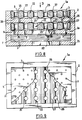
- the filter 1a represented in FIG. 1 comprises three plates 2, 2a, 2b. Plates 2 and 2a have each a peripheral edge 11 projecting adapted to come in contact with the adjacent plate, 2a, 2b, corresponding which is thus kept at a distance to provide a cavity, respectively 4, 5.
- the plate 2b has no such rim, which would unnecessarily increase the height of the filter 1.
- the top plate which is normally placed upstream side, is drilled with holes 3, 3a, 3b, of diameters different ascending in that order.
- the plates 2a, 2b have also holes of equal or different diameters.
- the holes in the intermediate plate 2a are arranged in staggered in relation to the holes in the end plates 2 and 2b. Holes 3, 3a, 3b may have other sections than circular.
- the plates 2, 2a, 2b are in known manner made of a refractory ceramic mineral material, by example in silica, and are able to withstand without deformation of the temperature of the cast metal.
- the filter 1 shown in Figure 2 has a plate 2 having holes 3 substantially similar diameter.
- the filter 1b shown in Figure 3 is consisting of two plates 2a whose peripheral edges 11 are adjacent and joined together by a collage 10.
- the heights of the flanges 11 are shown to be identical. but could be different.
- the two plates delimit a cavity 6.
- the filter 1e for liquid metal comprises three plates 2, 2a, 2b in refractory material, in contact with each other the others, by their periphery and defining between them several cavities 5, 6, 7.
- These plates 2, 2a, 2b have each a series of holes 3, allowing the passage and the filtration of the liquid metal which passes through the filter 1e in the direction of arrow D.
- At least one of the cavities 4, 5, 6 of the filter 1, 1a, 1b, 1c, 1d, 1e contains material for processing of the molten metal to be treated.
- the processing material 12 is in powder form and is retained by a film 13 of a material capable of melt, carbonize or calcine on contact with metal liquid to be treated.
- the particle size of the powder material is chosen according to the processing conditions wish.
- Film 13 made of a material capable of melt, carbonize or calcine on contact with metal to be treated is for example an aluminum foil or paper or plastic film, or composite sheet.
- the treatment material 12 is contained in sachets 8, 8a, 8b, made with said film 13 and placed in said cavity 4, 5, 6.
- the cavities 4 and 5 in Figure 1 contain each a bag, respectively 8, 8a, which fills partially or almost completely the cavity 4, 5, corresponding.
- These sachets 8, 8a can be identical or have different abilities.
- the cavity 6 in Figure 3 contains a bag 8b arranged, for example, eccentrically in said cavity 6.
- the cavity 6 formed between the two plates 2a is filled with material 12 of powder treatment, and the holes 3 of the plates 2a are closed by a film 13 of the aforementioned type arranged on the inside or on the outside of each plate 2a.
- a film 13 is fixed, for example glued, on the inside of the top plate.
- Another film 13 is fixed on the outer face of the bottom plate, the holes 3 being filled with processing material 12.
- the films 13 are fixed on the inside of the plates in the half view from the left and on the outside of these plates in the right half view. This last case corresponds to the maximum volume of treatment material 12 contained in filter 1c.
- the 12 powder treatment material is in the form compressed or sintered, and comes in the form of plates 14a, 14b or bars.
- the dimensions of the plates 14a, 14b or bars are less than or equal to the interior dimensions of cavity 6, so that these plates or bars can be movable inside the cavity 6 from the start of the flow under the action of turbulence caused by the arrival of molten metal in the cavity 6.
- a plate 14a of hexagonal outline and in the right half views a plate 14b of shape annular are for example compressed with a binder such as stearate or the like; we can also agglomerate under high pressure the material 12 of treatment prepared for example in the form crystallized.
- the plate 14a has a central hole 15 for the passage of metal. It could have other holes of various shapes and sizes.
- the processing materials can be desulfurization agents, for example magnesium and / or calcium carbide, and / or be thermogenic agents, by example of calcium carbide, and / or be agents inoculation and / or post-inoculation, and / or agents spheroidization, for example magnesium and / or earths rare and / or ferrosilicomagnesium, and / or agents addition alloys, for example alloys with molybdenum, boron, silicon, ferrosilicon, manganese, chromium, titanium, ferroaluminium, silicomischmetal, recarburizing agents, for example at carbon or graphite base, fluxes to modify the structure of the metal, such as sodium salts, phosphorus, boron, titanium, strontium, etc.
- desulfurization agents for example magnesium and / or calcium carbide
- thermogenic agents by example of calcium carbide, and / or be agents inoculation and / or post-inoculation, and / or agents s
- Figures 8 to 13 illustrate other modes of embodiment of the invention in which the material of treatment is a material 22, 23, 24 having properties inoculating against liquid metal.
- the cavities 5, 6 contain each an inoculating material 22.
- the material inoculant 22 is in the form of a plate with holes 25 for the passage of liquid metal, said plate extending over substantially the entire length and width of a cavity 5 or 6.
- each plate 22 adjacent to the bottom of the cavity 5 or 6 has a series of recesses 26 formed by a series of dihedrons parallel.
- the other side of the plate 22 also has recesses 27.
- the holes 25 in the plate 22 of inoculating material have a larger section as that of the holes 3 of the refractory material plates 2, 2a, 2b.
- the metal fills the recesses 26, which allows to obtain a large contact surface between the metal liquid and the inoculating material that promotes the reaction of the metal processing.
- the presence of the inoculating material 22 in the filter allows in combination with the filtration holes 3, improve the characteristics of the metal more efficiently only by a simple filtration operation.
- the inoculating material 23 is in the form of bars 28, 29 spaced apart extending over substantially the entire length and the width of the cavities 5 and 6 of the refractory plates 2, 2a.
- the bars 28, 29 are arranged in two overlapping and crossed layers, as shown in particular in Figure 11.
- the liquid metal licks the surface of the bars 28, 29 then accumulates at the bottom of the cavities 5, 6 before flowing down through holes 3.
- This realization also allows to realize a large contact surface between the liquid metal and the inoculating material making it possible to improve the yield of inoculating him.
- the face of the inoculating material plate 24 adjacent to the bottom of the cavity 5 of the refractory plate 2 has a recess 30 delimited by a peripheral rim 31 which rests on the bottom of the cavity 5.
- This plate 24 has holes 32 passage of liquid metal.
- the holes 32 of the plate 24 of inoculating material have a section larger than that of the holes 3 in the plate 2. From this fact, the liquid metal which is poured on the plate 24 cross the holes 32 then fill the recess 30 before flow through the openings 3 in the plate 2.
- the liquid metal is in contact with a large part of the surface of the inoculating material 24, which allows an action more effective inoculation.
- the material inoculant is in the form of a plate 2c with holes 3c of identical shape to that of refractory plates 2, 2b and occupying the place of one of them.
- At least one of the cavities of the plates 2, 2a, 2b in refractory material is filled with a filter material 20, for example in refractory fibers.
- this filter material 20 is disposed in a cavity 7 located (see Figures 8 and 10), in downstream of a cavity 5 or 6, containing an inoculating material 22 or 23 relative to the direction D of the passage of the liquid metal.
- This filter material 20 adds its effectiveness clean to further increase the performance of the filter according to the invention.
- the material inoculant is chosen from the following compounds: alloy of iron (e.g. Fe-Si alloy), magnesium and compounds of magnesium, calcium and its compounds, lithium compounds, compounds of strontium and compounds of barium, silicon, zirconium, aluminum, rare earths, graphite and carbon.
- the plates 14a, 14b compressed or sintered can be replaced by solid molded plates.
Landscapes
- Chemical & Material Sciences (AREA)
- Engineering & Computer Science (AREA)
- Chemical Kinetics & Catalysis (AREA)
- Mechanical Engineering (AREA)
- Materials Engineering (AREA)
- Metallurgy (AREA)
- Organic Chemistry (AREA)
- Manufacture And Refinement Of Metals (AREA)
- Casting Support Devices, Ladles, And Melt Control Thereby (AREA)
- Filtering Materials (AREA)
Claims (17)
- Vorrichtung (1d, 1e) zum Filtern und Behandeln von schmelzflüssigem Metall, die aufweist eine Reihe von mindestens zwei Platten (2, 2a, 2b) aus mineralischem, hitzebeständigem Material, die zwischen sich einen oder mehrere Hohlräume (4, 5, 6) bilden, wobei die Platten jeweils eine Reihe von Löchern (3, 3a, 3b) aufweisen, die den Durchgang des schmelzflüssigen Metalls erlauben, wobei mindestens einer der Hohlräume (4, 5, 6) ein Material (12, 22, 23, 24) für die Behandlung dieses Metalls enthält, dadurch gekennzeichnet, daß die Platten (2, 2a, 2b) Filterplatten sind, die jeweils eine Reihe von Filterlöchern (3, 3a, 3b) aufweisen, die den Durchgang und die Filtration des schmelzflüssigen Metalls erlauben, daß zwei benachbarte Filterplatten (2, 2a; 2a, 2b) in Kontakt miteinander entlang ihres Umfangs zusammengesetzt sind, daß das Behandlungsmaterial sich in Form von Platten (14a, 14b, 22) oder Barren (28, 29) findet und daß die Platte (14a, 14b, 22) oder die Barren (28, 29) eine solche Form haben, daß sie, gesehen in Richtung des Durchgangs des flüssigen Metalls, über den Filterplatten (2, 2a, 2b) mindestens einen Bereich unbedeckt lassen, der Filterlöcher (3, 3a, 3b) aufweist, um zu erlauben, daß das flüssige Metall, das in den Hohlraum (4, 5, 6) eingedrungen ist, mit dem Behandlungsmaterial der Platte (14a, 14b, 22) oder der Barren (28, 29) in Kontakt kommt und um diese Platte (14a, 14b, 22) oder diese Barren (28, 29) herum weiter durch die Filterlöcher (3, 3a, 3b) der zweiten Filterplatte (2, 2a, 2b) abläuft.
- Vorrichtung nach Anspruch 1, dadurch gekennzeichnet, daß das Behandlungsmaterial in Form von Platten (14a, 14b, 22) oder Barren (28, 29) ist, die gepreßt oder gesintert oder geformt sind.
- Vorrichtung nach einem der Ansprüche 1 oder 2, dadurch gekennzeichnet, daß die Abmessungen dieser Platten (14a, 14b, 22) oder Barren (28, 29) kleiner als die oder gleich den inneren Abmessungen des Hohlraums (5, 6) ist, der verwendet wird, um sie aufzunehmen.
- Vorrichtung nach einem der Ansprüche 1, 2 oder 3, dadurch gekennzeichnet, daß das Behandlungsmaterial in Form einer Platte (14a, 14b, 22) ist, die ein oder mehrere Löcher (15, 25) zum Durchgang des flüssigen Metalls aufweisen können.
- Vorrichtung nach Anspruch 4, dadurch gekennzeichnet, daß mindestens eine Seite der Platte (22), die dem Boden des Hohlraumes (5, 6) benachbart ist, eine Reihe von Vertiefungen (26) aufweist.
- Vorrichtung nach Anspruch 5, dadurch gekennzeichnet, daß diese Vertiefungen (26) gebildet sind durch eine Reihe von parallelen V-Winkeln.
- Vorrichtung nach einem der Ansprüche 5 oder 6, dadurch gekennzeichnet, daß die andere Seite dieser Platte (22) gleichermaßen Vertiefungen (27) aufweist.
- Vorrichtung nach einem der Ansprüche 5 bis 7, dadurch gekennzeichnet, daß die Löcher (25) der Platte (22) aus Behandlungsmaterial einen Querschnitt haben, der größer ist als derjenige der Löcher (3, 3a, 3b) der Platten (2, 2a, 2b) aus hitzeheständigem Material.
- Vorrichtung nach einem der Ansprüche 1 bis 3, dadurch gekennzeichnet, daß das Behandlungsmaterial in Form von gesperrt gesetzten Barren (28, 29) ist, die sich im wesentlichen über die gesamte Länge und die Breite eines Hohlraumes (5, 6) erstrecken.
- Vorrichtung nach Anspruch 9, dadurch gekennzeichnet, daß die Barren (28, 29) in mindestens zwei übereinander liegenden und kreuzenden Lagen angeordnet sind.
- Vorrichtung nach einem der Ansprüche 1 bis 10, dadurch gekennzeichnet, daß mindestens einer der Hohlräume (7) der Platten (2b) mit einem Filtermaterial (20) gefüllt ist.
- Vorrichtung nach Anspruch 11, dadurch gekennzeichnet, daß das Filtermaterial (20) in einem Hohlraum (7) angeordnet ist, der stromabwärts eines Hohlraumes (5, 6) angeordnet ist, der ein Behandlungsmaterial einschließt, bezogen auf die Richtung (D) des Durchgangs des flüssigen Metalls.
- Vorrichtung nach einem der Ansprüche 1 bis 12, dadurch gekennzeichnet, daß das Behandlungsmaterial ausgewählt ist aus den entschwefelnden, wärmeerzeugenden, impfenden, weichglühenden, rückkohlenden, reduzierenden Produkten und Modifikator-Produkten und den Zusatzlegierungen.
- Vorrichtung nach Anspruch 13, dadurch gekennzeichnet, daß das Gewicht des Behandlungsmaterials enthalten ist zwischen ungefähr 0,001 % und 1 % des Gewichts des schmelzflüssigen Metalls.
- Vorrichtung nach Anspruch 13 oder 14, dadurch gekennzeichnet, daß das Behandlungsmaterial ein Impfmaterial ist.
- Vorrichtung nach Anspruch 15, dadurch gekennzeichnet, daß das Impfmaterial ausgewählt ist aus folgenden Zusammensetzungen: Legierung aus Eisen, Magnesium, und Magnesium-Verbindungen, Kalzium und seinen Verbindungen, Lithium-Verbindungen, Strontium-Verbindungen und Barium-Verbindungen, Silizium, Zirkonium, Aluminium, seltene Erden, Graphit, Kohlenstoff.
- Verwendung einer Vorrichtung nach einem der vorhergehenden Ansprüche in einem Formgießverfahren für schmelzflüssiges Metall, das die Schritte des Einsetzens eines Filters und der Behandlung des Metalls im Verlauf des Gießens aufweist.
Applications Claiming Priority (6)
| Application Number | Priority Date | Filing Date | Title |
|---|---|---|---|
| LU88124A LU88124A1 (fr) | 1992-05-29 | 1992-05-29 | Filtre pour metal liquide |
| LU88124 | 1992-05-29 | ||
| FR9213039 | 1992-10-30 | ||
| FR9213039A FR2697444B1 (fr) | 1992-10-30 | 1992-10-30 | Filtre pour métal liquide à inoculant. |
| FR9300062A FR2691654B1 (fr) | 1992-05-29 | 1993-01-06 | Procédé pour traiter du métal en fusion dans une opération de coulée avec interposition d'un filtre, et filtre pour la mise en Óoeuvre de ce procédé. |
| FR9300062 | 1993-01-06 |
Publications (2)
| Publication Number | Publication Date |
|---|---|
| EP0578517A1 EP0578517A1 (de) | 1994-01-12 |
| EP0578517B1 true EP0578517B1 (de) | 1998-11-11 |
Family
ID=27252674
Family Applications (1)
| Application Number | Title | Priority Date | Filing Date |
|---|---|---|---|
| EP93401373A Expired - Lifetime EP0578517B1 (de) | 1992-05-29 | 1993-05-28 | Verfahren zum Behandeln von schmelzflüsssigem Metall während eines Giessvorganges unter Verwendung eines Filters sowie dazu verwendete Filter |
Country Status (5)
| Country | Link |
|---|---|
| EP (1) | EP0578517B1 (de) |
| JP (1) | JPH06108170A (de) |
| CA (1) | CA2097261C (de) |
| DE (1) | DE69322006T2 (de) |
| ES (1) | ES2126637T3 (de) |
Cited By (1)
| Publication number | Priority date | Publication date | Assignee | Title |
|---|---|---|---|---|
| KR100904671B1 (ko) | 2002-06-03 | 2009-06-25 | 비수비우스 크루서블 컴패니 | 용강 여과용 필터 장치 |
Families Citing this family (4)
| Publication number | Priority date | Publication date | Assignee | Title |
|---|---|---|---|---|
| FR2774611B1 (fr) * | 1998-02-11 | 2000-04-28 | Daussan & Co | Dispositif pour filtrer et traiter du metal en fusion |
| FR2780322B3 (fr) * | 1998-06-25 | 2000-05-12 | Daussan & Co | Procede pour preparer un moule de coulee |
| GB0613001D0 (en) * | 2006-06-30 | 2006-08-09 | Juma Kassim A | A filter |
| DE102018201577B4 (de) * | 2017-02-03 | 2020-02-06 | Technische Universität Bergakademie Freiberg | Verfahren zur Herstellung eines Metallschmelze-Hybrid-Filters und keramischer Metallschmelze-Hybrid-Filter |
Family Cites Families (7)
| Publication number | Priority date | Publication date | Assignee | Title |
|---|---|---|---|---|
| US3658115A (en) * | 1970-11-30 | 1972-04-25 | Gen Motors Corp | Method of inoculating nodular cast iron |
| DE2608282A1 (de) * | 1976-02-28 | 1977-09-08 | Baur Eduard Dr Ing | Vorrichtung zum impfen und/oder legieren von metallischen schmelzen zum herstellen von gusstuecken |
| DE3509113A1 (de) * | 1985-03-14 | 1986-09-18 | Stettner & Co, 8560 Lauf | Vorrichtung zum filtern von metallischen schmelzen |
| FR2593077B1 (fr) * | 1986-01-23 | 1990-10-19 | Desobeau Jacques | Filtre en matiere refractaire. |
| JPS62185859A (ja) * | 1986-02-10 | 1987-08-14 | Kubota Ltd | 型内接種用反応容器 |
| GB8604569D0 (en) * | 1986-02-25 | 1986-04-03 | Foseco Int | Casting of molten ferrous metal |
| IT1189162B (it) * | 1986-06-11 | 1988-01-28 | Oet Metalconsult Srl | Procedimento di trattamento di degasaggio,affinaggio o filtrazione di metalli o leghe allo stato liquido e relativo dispositivo |
-
1993
- 1993-05-28 DE DE69322006T patent/DE69322006T2/de not_active Expired - Fee Related
- 1993-05-28 ES ES93401373T patent/ES2126637T3/es not_active Expired - Lifetime
- 1993-05-28 CA CA002097261A patent/CA2097261C/en not_active Expired - Fee Related
- 1993-05-28 EP EP93401373A patent/EP0578517B1/de not_active Expired - Lifetime
- 1993-05-31 JP JP5149797A patent/JPH06108170A/ja active Pending
Cited By (1)
| Publication number | Priority date | Publication date | Assignee | Title |
|---|---|---|---|---|
| KR100904671B1 (ko) | 2002-06-03 | 2009-06-25 | 비수비우스 크루서블 컴패니 | 용강 여과용 필터 장치 |
Also Published As
| Publication number | Publication date |
|---|---|
| EP0578517A1 (de) | 1994-01-12 |
| CA2097261C (en) | 2001-07-24 |
| JPH06108170A (ja) | 1994-04-19 |
| CA2097261A1 (en) | 1993-11-30 |
| ES2126637T3 (es) | 1999-04-01 |
| DE69322006D1 (de) | 1998-12-17 |
| DE69322006T2 (de) | 1999-06-10 |
Similar Documents
| Publication | Publication Date | Title |
|---|---|---|
| FR2626508A1 (fr) | Moule de coulee de metaux, equipe d'un manchon contenant un filtre | |
| EP0578517B1 (de) | Verfahren zum Behandeln von schmelzflüsssigem Metall während eines Giessvorganges unter Verwendung eines Filters sowie dazu verwendete Filter | |
| EP0127521B1 (de) | Verfahren und Vorrichtung zum Behandeln eines unter Niederdruck gegossenen Metalls, insbesondere zum Impfen der Schmelze | |
| EP1091818B1 (de) | Verfahren zum präparieren einer giessform | |
| FR2774611A1 (fr) | Dispositif pour filtrer et traiter du metal en fusion | |
| FR2556996A1 (fr) | Procede d'alimentation de moules de fonderie en alliages metalliques sous pression differentielle controlee | |
| EP0386384B1 (de) | Verfahren zum Vollformgiessen von metallischen Gegenständen unter Druck | |
| FR2552351A1 (fr) | Procedes et moules a revetement interieur pour la coulee centrifuge | |
| FR2691654A1 (fr) | Procédé pour traiter du métal en fusion dans une opération de coulée avec interposition d'un filtre, et filtre pour la mise en Óoeuvre de ce procédé. | |
| EP0242347A2 (de) | Vorrichtung zum Giessen einer flüssig-festen Mischung | |
| EP2490842A1 (de) | Verfahren zur herstellung eines metallblocks mit einer bohrung sowie entsprechender metallblock und pressform | |
| EP0519798B1 (de) | Verfahren zur Herstellung einer Hochleistung-Sprengladung und Vorrichtung zur Durchführung dieses Verfahren | |
| WO2002060618A1 (fr) | Procede de traitement et de coulee d"alliages oxydables | |
| EP0112790B1 (de) | Verfahren zum GieBen eines Bremsrotors | |
| FR2459834A1 (fr) | Procede et moule pour la fabrication de pieces de fonderie en fontes de fer-carbone a graphite spheroidal ou compact | |
| FR2697444A1 (fr) | Filtre pour métal liquide à inoculant. | |
| FR2648373A1 (fr) | Pot de fonderie | |
| FR2669041A1 (fr) | Procede pour le traitement d'un metal en fusion et son transfert dans un espace recepteur et systeme pour la mise en óoeuvre de ce procede. | |
| EP0223722A1 (de) | Verfahren und Vorrichtung zum Einblasen von pulverigen Zusätzen in den Strahl einer Metallschmelze unter vermindertem Druck | |
| FR2526689A1 (fr) | Procede et appareil pour la coulee continue ou semi-continue de lingots de metal | |
| FR2597770A1 (fr) | Dispositif de moulage de pieces minces et de grandes dimensions en alliages d'aluminium | |
| BE723523A (de) | ||
| BE508973A (de) | ||
| FR2644087A2 (fr) | Perfectionnement au procede de moulage a mousse perdue de pieces metalliques | |
| LU85378A1 (fr) | Procede et dispositif de traitement d'un metal liquide moule a basse pression,notamment pour l'inoculation de la fonte |
Legal Events
| Date | Code | Title | Description |
|---|---|---|---|
| PUAI | Public reference made under article 153(3) epc to a published international application that has entered the european phase |
Free format text: ORIGINAL CODE: 0009012 |
|
| 17P | Request for examination filed |
Effective date: 19930609 |
|
| AK | Designated contracting states |
Kind code of ref document: A1 Designated state(s): BE DE ES GB IT LU |
|
| 17Q | First examination report despatched |
Effective date: 19961001 |
|
| GRAG | Despatch of communication of intention to grant |
Free format text: ORIGINAL CODE: EPIDOS AGRA |
|
| GRAG | Despatch of communication of intention to grant |
Free format text: ORIGINAL CODE: EPIDOS AGRA |
|
| GRAG | Despatch of communication of intention to grant |
Free format text: ORIGINAL CODE: EPIDOS AGRA |
|
| GRAH | Despatch of communication of intention to grant a patent |
Free format text: ORIGINAL CODE: EPIDOS IGRA |
|
| GRAH | Despatch of communication of intention to grant a patent |
Free format text: ORIGINAL CODE: EPIDOS IGRA |
|
| GRAA | (expected) grant |
Free format text: ORIGINAL CODE: 0009210 |
|
| AK | Designated contracting states |
Kind code of ref document: B1 Designated state(s): BE DE ES GB IT LU |
|
| REF | Corresponds to: |
Ref document number: 69322006 Country of ref document: DE Date of ref document: 19981217 |
|
| GBT | Gb: translation of ep patent filed (gb section 77(6)(a)/1977) |
Effective date: 19981217 |
|
| REG | Reference to a national code |
Ref country code: ES Ref legal event code: FG2A Ref document number: 2126637 Country of ref document: ES Kind code of ref document: T3 |
|
| PG25 | Lapsed in a contracting state [announced via postgrant information from national office to epo] |
Ref country code: LU Free format text: LAPSE BECAUSE OF NON-PAYMENT OF DUE FEES Effective date: 19990528 |
|
| PLBE | No opposition filed within time limit |
Free format text: ORIGINAL CODE: 0009261 |
|
| STAA | Information on the status of an ep patent application or granted ep patent |
Free format text: STATUS: NO OPPOSITION FILED WITHIN TIME LIMIT |
|
| 26N | No opposition filed | ||
| PGFP | Annual fee paid to national office [announced via postgrant information from national office to epo] |
Ref country code: BE Payment date: 20010507 Year of fee payment: 9 |
|
| REG | Reference to a national code |
Ref country code: GB Ref legal event code: IF02 |
|
| GBPC | Gb: european patent ceased through non-payment of renewal fee |
Effective date: 20020528 |
|
| REG | Reference to a national code |
Ref country code: GB Ref legal event code: 728V |
|
| REG | Reference to a national code |
Ref country code: GB Ref legal event code: 728Y |
|
| BERR | Be: reestablished |
Owner name: *ELKEM ASA Effective date: 20030520 |
|
| REG | Reference to a national code |
Ref country code: GB Ref legal event code: 732E |
|
| REG | Reference to a national code |
Ref country code: ES Ref legal event code: PC2A |
|
| PGFP | Annual fee paid to national office [announced via postgrant information from national office to epo] |
Ref country code: ES Payment date: 20080619 Year of fee payment: 16 Ref country code: DE Payment date: 20080605 Year of fee payment: 16 |
|
| PGFP | Annual fee paid to national office [announced via postgrant information from national office to epo] |
Ref country code: IT Payment date: 20080528 Year of fee payment: 16 |
|
| PGFP | Annual fee paid to national office [announced via postgrant information from national office to epo] |
Ref country code: GB Payment date: 20080528 Year of fee payment: 16 |
|
| GBPC | Gb: european patent ceased through non-payment of renewal fee |
Effective date: 20090528 |
|
| PG25 | Lapsed in a contracting state [announced via postgrant information from national office to epo] |
Ref country code: GB Free format text: LAPSE BECAUSE OF NON-PAYMENT OF DUE FEES Effective date: 20090528 |
|
| PG25 | Lapsed in a contracting state [announced via postgrant information from national office to epo] |
Ref country code: DE Free format text: LAPSE BECAUSE OF NON-PAYMENT OF DUE FEES Effective date: 20091201 |
|
| REG | Reference to a national code |
Ref country code: ES Ref legal event code: FD2A Effective date: 20090529 |
|
| PG25 | Lapsed in a contracting state [announced via postgrant information from national office to epo] |
Ref country code: ES Free format text: LAPSE BECAUSE OF NON-PAYMENT OF DUE FEES Effective date: 20090529 |
|
| PG25 | Lapsed in a contracting state [announced via postgrant information from national office to epo] |
Ref country code: IT Free format text: LAPSE BECAUSE OF NON-PAYMENT OF DUE FEES Effective date: 20090528 |