EP0579018B1 - Verfahren zur Herstellung einer Metalloxidschicht, Vakuumbehandlungsanlage hierfür sowie mit mindestens einer Metalloxidschicht beschichteter Teil - Google Patents
Verfahren zur Herstellung einer Metalloxidschicht, Vakuumbehandlungsanlage hierfür sowie mit mindestens einer Metalloxidschicht beschichteter Teil Download PDFInfo
- Publication number
- EP0579018B1 EP0579018B1 EP93110252A EP93110252A EP0579018B1 EP 0579018 B1 EP0579018 B1 EP 0579018B1 EP 93110252 A EP93110252 A EP 93110252A EP 93110252 A EP93110252 A EP 93110252A EP 0579018 B1 EP0579018 B1 EP 0579018B1
- Authority
- EP
- European Patent Office
- Prior art keywords
- metal
- oxygen
- rate
- process according
- released
- Prior art date
- Legal status (The legal status is an assumption and is not a legal conclusion. Google has not performed a legal analysis and makes no representation as to the accuracy of the status listed.)
- Expired - Lifetime
Links
- 229910044991 metal oxide Inorganic materials 0.000 title claims abstract description 24
- 150000004706 metal oxides Chemical class 0.000 title claims abstract description 24
- 238000000034 method Methods 0.000 title claims description 61
- 230000008569 process Effects 0.000 title claims description 46
- 238000004519 manufacturing process Methods 0.000 title claims description 10
- 238000009489 vacuum treatment Methods 0.000 title claims description 8
- 239000002184 metal Substances 0.000 claims abstract description 90
- 229910052751 metal Inorganic materials 0.000 claims abstract description 90
- 229910052760 oxygen Inorganic materials 0.000 claims abstract description 88
- 239000001301 oxygen Substances 0.000 claims abstract description 86
- QVGXLLKOCUKJST-UHFFFAOYSA-N atomic oxygen Chemical compound [O] QVGXLLKOCUKJST-UHFFFAOYSA-N 0.000 claims abstract description 85
- 238000007254 oxidation reaction Methods 0.000 claims abstract description 50
- 230000003647 oxidation Effects 0.000 claims abstract description 49
- 239000000758 substrate Substances 0.000 claims abstract description 27
- 239000002923 metal particle Substances 0.000 claims abstract description 26
- 150000002500 ions Chemical class 0.000 claims abstract description 8
- 238000001704 evaporation Methods 0.000 claims description 21
- 230000008020 evaporation Effects 0.000 claims description 20
- 238000010894 electron beam technology Methods 0.000 claims description 18
- 239000007789 gas Substances 0.000 claims description 18
- 238000000576 coating method Methods 0.000 claims description 12
- 239000011248 coating agent Substances 0.000 claims description 9
- 238000005259 measurement Methods 0.000 claims description 9
- 230000004044 response Effects 0.000 claims description 6
- 239000007787 solid Substances 0.000 claims description 6
- 238000001514 detection method Methods 0.000 claims description 5
- 230000035945 sensitivity Effects 0.000 claims description 5
- 238000011065 in-situ storage Methods 0.000 claims description 4
- 239000000463 material Substances 0.000 claims description 4
- 239000002245 particle Substances 0.000 claims description 4
- 238000005566 electron beam evaporation Methods 0.000 claims description 3
- CBENFWSGALASAD-UHFFFAOYSA-N Ozone Chemical compound [O-][O+]=O CBENFWSGALASAD-UHFFFAOYSA-N 0.000 claims description 2
- 238000006243 chemical reaction Methods 0.000 claims description 2
- 238000009826 distribution Methods 0.000 claims description 2
- 239000000178 monomer Substances 0.000 claims description 2
- 238000009434 installation Methods 0.000 claims 14
- 150000002926 oxygen Chemical class 0.000 claims 2
- 230000005855 radiation Effects 0.000 claims 2
- 230000003247 decreasing effect Effects 0.000 claims 1
- 230000008021 deposition Effects 0.000 claims 1
- 238000009616 inductively coupled plasma Methods 0.000 claims 1
- 230000036962 time dependent Effects 0.000 claims 1
- 239000010410 layer Substances 0.000 description 69
- 230000001105 regulatory effect Effects 0.000 description 6
- 229910052594 sapphire Inorganic materials 0.000 description 4
- 239000010980 sapphire Substances 0.000 description 4
- 238000001883 metal evaporation Methods 0.000 description 3
- 239000002356 single layer Substances 0.000 description 3
- 230000005668 Josephson effect Effects 0.000 description 2
- 239000012298 atmosphere Substances 0.000 description 2
- 230000006835 compression Effects 0.000 description 2
- 238000007906 compression Methods 0.000 description 2
- 238000010276 construction Methods 0.000 description 2
- 238000011109 contamination Methods 0.000 description 2
- 239000003989 dielectric material Substances 0.000 description 2
- 230000000694 effects Effects 0.000 description 2
- 239000010408 film Substances 0.000 description 2
- 229910052741 iridium Inorganic materials 0.000 description 2
- GKOZUEZYRPOHIO-UHFFFAOYSA-N iridium atom Chemical compound [Ir] GKOZUEZYRPOHIO-UHFFFAOYSA-N 0.000 description 2
- 229920006395 saturated elastomer Polymers 0.000 description 2
- 239000004065 semiconductor Substances 0.000 description 2
- 238000003860 storage Methods 0.000 description 2
- 238000012935 Averaging Methods 0.000 description 1
- MYMOFIZGZYHOMD-UHFFFAOYSA-N Dioxygen Chemical compound O=O MYMOFIZGZYHOMD-UHFFFAOYSA-N 0.000 description 1
- -1 Oxygen ion Chemical class 0.000 description 1
- 229910004298 SiO 2 Inorganic materials 0.000 description 1
- 229910009203 Y-Ba-Cu-O Inorganic materials 0.000 description 1
- 238000010521 absorption reaction Methods 0.000 description 1
- 230000009471 action Effects 0.000 description 1
- 239000000853 adhesive Substances 0.000 description 1
- 230000001070 adhesive effect Effects 0.000 description 1
- 239000002390 adhesive tape Substances 0.000 description 1
- 230000015572 biosynthetic process Effects 0.000 description 1
- 230000000903 blocking effect Effects 0.000 description 1
- 239000003990 capacitor Substances 0.000 description 1
- 229910000420 cerium oxide Inorganic materials 0.000 description 1
- 230000008859 change Effects 0.000 description 1
- 239000003795 chemical substances by application Substances 0.000 description 1
- 238000004140 cleaning Methods 0.000 description 1
- 230000001276 controlling effect Effects 0.000 description 1
- 238000005336 cracking Methods 0.000 description 1
- 230000007547 defect Effects 0.000 description 1
- 230000001419 dependent effect Effects 0.000 description 1
- 229910001882 dioxygen Inorganic materials 0.000 description 1
- 238000006056 electrooxidation reaction Methods 0.000 description 1
- 238000005538 encapsulation Methods 0.000 description 1
- 230000005669 field effect Effects 0.000 description 1
- 238000010438 heat treatment Methods 0.000 description 1
- 230000006872 improvement Effects 0.000 description 1
- 239000012535 impurity Substances 0.000 description 1
- 238000009776 industrial production Methods 0.000 description 1
- 238000009413 insulation Methods 0.000 description 1
- 239000012212 insulator Substances 0.000 description 1
- 238000002955 isolation Methods 0.000 description 1
- 238000003698 laser cutting Methods 0.000 description 1
- 230000007774 longterm Effects 0.000 description 1
- 230000007246 mechanism Effects 0.000 description 1
- 150000002739 metals Chemical class 0.000 description 1
- 238000010327 methods by industry Methods 0.000 description 1
- 239000002052 molecular layer Substances 0.000 description 1
- 238000012544 monitoring process Methods 0.000 description 1
- 230000003287 optical effect Effects 0.000 description 1
- BMMGVYCKOGBVEV-UHFFFAOYSA-N oxo(oxoceriooxy)cerium Chemical compound [Ce]=O.O=[Ce]=O BMMGVYCKOGBVEV-UHFFFAOYSA-N 0.000 description 1
- 238000001139 pH measurement Methods 0.000 description 1
- 238000002161 passivation Methods 0.000 description 1
- 238000004886 process control Methods 0.000 description 1
- 239000011241 protective layer Substances 0.000 description 1
- 238000005086 pumping Methods 0.000 description 1
- 230000009257 reactivity Effects 0.000 description 1
- 238000004904 shortening Methods 0.000 description 1
- 239000007784 solid electrolyte Substances 0.000 description 1
- 230000035882 stress Effects 0.000 description 1
- 239000002887 superconductor Substances 0.000 description 1
- 238000012360 testing method Methods 0.000 description 1
- 230000008646 thermal stress Effects 0.000 description 1
- 239000010409 thin film Substances 0.000 description 1
- 230000007704 transition Effects 0.000 description 1
- 239000011364 vaporized material Substances 0.000 description 1
- 239000006200 vaporizer Substances 0.000 description 1
Images


Classifications
-
- C—CHEMISTRY; METALLURGY
- C23—COATING METALLIC MATERIAL; COATING MATERIAL WITH METALLIC MATERIAL; CHEMICAL SURFACE TREATMENT; DIFFUSION TREATMENT OF METALLIC MATERIAL; COATING BY VACUUM EVAPORATION, BY SPUTTERING, BY ION IMPLANTATION OR BY CHEMICAL VAPOUR DEPOSITION, IN GENERAL; INHIBITING CORROSION OF METALLIC MATERIAL OR INCRUSTATION IN GENERAL
- C23C—COATING METALLIC MATERIAL; COATING MATERIAL WITH METALLIC MATERIAL; SURFACE TREATMENT OF METALLIC MATERIAL BY DIFFUSION INTO THE SURFACE, BY CHEMICAL CONVERSION OR SUBSTITUTION; COATING BY VACUUM EVAPORATION, BY SPUTTERING, BY ION IMPLANTATION OR BY CHEMICAL VAPOUR DEPOSITION, IN GENERAL
- C23C14/00—Coating by vacuum evaporation, by sputtering or by ion implantation of the coating forming material
- C23C14/22—Coating by vacuum evaporation, by sputtering or by ion implantation of the coating forming material characterised by the process of coating
- C23C14/54—Controlling or regulating the coating process
-
- C—CHEMISTRY; METALLURGY
- C23—COATING METALLIC MATERIAL; COATING MATERIAL WITH METALLIC MATERIAL; CHEMICAL SURFACE TREATMENT; DIFFUSION TREATMENT OF METALLIC MATERIAL; COATING BY VACUUM EVAPORATION, BY SPUTTERING, BY ION IMPLANTATION OR BY CHEMICAL VAPOUR DEPOSITION, IN GENERAL; INHIBITING CORROSION OF METALLIC MATERIAL OR INCRUSTATION IN GENERAL
- C23C—COATING METALLIC MATERIAL; COATING MATERIAL WITH METALLIC MATERIAL; SURFACE TREATMENT OF METALLIC MATERIAL BY DIFFUSION INTO THE SURFACE, BY CHEMICAL CONVERSION OR SUBSTITUTION; COATING BY VACUUM EVAPORATION, BY SPUTTERING, BY ION IMPLANTATION OR BY CHEMICAL VAPOUR DEPOSITION, IN GENERAL
- C23C14/00—Coating by vacuum evaporation, by sputtering or by ion implantation of the coating forming material
- C23C14/0021—Reactive sputtering or evaporation
-
- H—ELECTRICITY
- H01—ELECTRIC ELEMENTS
- H01J—ELECTRIC DISCHARGE TUBES OR DISCHARGE LAMPS
- H01J2237/00—Discharge tubes exposing object to beam, e.g. for analysis treatment, etching, imaging
- H01J2237/18—Vacuum control means
- H01J2237/182—Obtaining or maintaining desired pressure
-
- H—ELECTRICITY
- H01—ELECTRIC ELEMENTS
- H01J—ELECTRIC DISCHARGE TUBES OR DISCHARGE LAMPS
- H01J2237/00—Discharge tubes exposing object to beam, e.g. for analysis treatment, etching, imaging
- H01J2237/20—Positioning, supporting, modifying or maintaining the physical state of objects being observed or treated
- H01J2237/2001—Maintaining constant desired temperature
-
- H—ELECTRICITY
- H01—ELECTRIC ELEMENTS
- H01J—ELECTRIC DISCHARGE TUBES OR DISCHARGE LAMPS
- H01J2237/00—Discharge tubes exposing object to beam, e.g. for analysis treatment, etching, imaging
- H01J2237/30—Electron or ion beam tubes for processing objects
- H01J2237/31—Processing objects on a macro-scale
- H01J2237/3132—Evaporating
Definitions
- the present invention relates to a method according to the The preamble of claim 1, a vacuum treatment plant for Execution of said method according to that of claim 29 and one with at least one metal oxide layer coated part according to claim 43.
- the term "metal oxide” the oxides of the semiconductors should also be understood.
- microcracks can in all cases cancel the function of the oxide layer. For example when used as a pH sensor layer due to such microcracks the layer shorted.
- EP-A-0 302 506 it is known in the manufacture electrically superconducting layers the evaporation release rate to regulate and the energy on the to be coated Oxygen ion striking substrate as deep as possible to keep.
- the substrate temperature is kept at 800 ° C.
- the aim of the present invention is to initiate a method to propose the type mentioned, by means of which the mentioned Metal oxide layers can be manufactured industrially and the mentioned requirements regarding micro cracks, Impurity and adhesive strength are sufficient, as well as a Vacuum treatment plant, by means of which the named Layers can be produced, as well as, further, parts, which are manufactured industrially to meet the requirements mentioned.
- the metal continues according to the wording released from claim 2 in the vacuum chamber.
- Claim 3 proceeded, which allowed the release rate to guide exactly, and enables the mentioned Degree of oxidation profile, according to the simultaneously supplied amount of oxygen per unit of time, according to a given target profile to realize.
- the whole should be understood as the release area Area of a metal particle source from within metal particles released during the coating time will.
- the metal is preferably according to the wording of claim 6 released by evaporation, thereby preferably by electron beam evaporation Process, particularly in the one to be described Way is exactly manageable.
- the amount of metal is preferably after Wording of claim 7 during the coating process measured.
- the measurement in the solid angle range under which the underlay with its area to be coated Source of the released metal sees. So that exists essentially proportionality between the Quantity of metal per unit of time determined at the measuring location and the amount of metal deposited on the pad per unit of time and area.
- the measurement is preferably carried out after the Wording of claim 8 made and further following the wording of claim 9. With that, at constant amount of oxygen supplied per unit of time, the degree of oxidation at the building up Shift regulated or regulated or at Providing the amount of oxygen supplied per unit of time posed with.
- the preferred response time corresponds to this ⁇ msec especially the flight time of electron-beam vaporized particles in the mentioned maximum kinetic energy of approx. 10 eV above a distance of 50cm between the source and one mounted in this regard at a distance of 50cm coating base.
- the one for measuring the Rate released metal rate sensor used arranged according to the wording of claim 15 this preferably realized by providing a pressure stage between metal source and rate sensor on the one hand and oxygen intake and pad on the other.
- Two of the three sizes are preferably Document temperature per unit of time and per unit of time amount of oxygen admitted or rate of release, kept constant.
- the metal oxide layer mentioned should it be one or two sided on a metal surface be made to fit, whereby then preferably selected the same metal as metal from which the oxide of the layer is also formed becomes. Also responsible for the formation of micro cracks is, as has been mentioned, the liability of the invention prepared metal oxide layer the document, in the present case on the minimum a called metal surface.
- the degree of oxidation the building layer in particular by keeping the surface temperature constant and by setting the amount of oxygen admitted per unit of time carried out at longer intervals, whereby, in a smaller positioning time grid, the rate of metal released is set.
- adjustment steps and adjustment times of the released Metal rate especially in the proposed evaporation rate control to be described later, are much finer or shorter than Positioning times of gas inflow regulations, taking into account their inertia caused by supply lines etc.
- excited oxygen can be used in Form of ozone and / or oxygen monomer and / or electronically excited oxygen or ions.
- the kinetic energy not even of the excited oxygen be more than 10 eV, so that only the oxidation yield to increase and thereby no undefined Influencing first the document, then the To give layer surface properties.
- a vacuum treatment plant to carry out the explained Procedure is according to the wording of claim 29 trained, preferred variants this plant claims 30 to 42.
- parts coated according to the invention can be produced with an unexpectedly low reject rate.
- parts coated with at least one metal oxide layer can be produced at the same time, whereby, given a given surface area of the individual parts of at least 15 mm 2, at least 30%, preferably at least 40% of the parts are selectively conductive for a maximum of specified ions and are therefore usable as sensors. There is even a yield higher than 90%; At the same time, the life of the parts, for example as sensors, is significantly increased.
- the yield percentages mentioned relate to surface areas of the coating of at least 15 mm 2 .
- a yield of 90% means that 1350mm 2 of 1500mm 2 of coated surface are free of microcracks.
- the parts can already be coated as such or only as a "large substrate", which afterwards, such as. through a laser cutting process, into the individual parts to be used is divided.
- an electron beam evaporator is used as a metal source and this for obtaining highest precision regarding guidance, preferably made by means of an electron beam source will, as in the published publications the applicant DE-OS-39 21 040 and 39 29 475 is described or after those described there Control procedures, these two documents are hereby as an integral part of the present description explained.
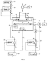
- FIG. 1 A preferred embodiment variant is shown schematically in FIG a vacuum treatment plant according to the invention shown, based on which also the inventive Procedure to be explained.
- a movable or, as shown, stationary workpiece carrier 3 is provided in a known manner.
- the workpiece carrier 3 is, as shown schematically with the heating element 5, heated.
- a gas shower 7 is provided, preferably designed as an annular gas shower, as shown, which is connected via a mass flow actuator 9 to an oxygen storage tank 11.
- the actuator 9 can be controlled at an input E 9 .
- the workpiece carrier 3 opposite is an electron beam evaporator source with electron beam generator 13 intended.
- the electron beam evaporator unit 13 has a control input E 13 , by means of which the evaporation rate r, defined as per unit time and averaged over the release or evaporation surface of the evaporated amount of evaporated metal, can be set sufficiently quickly and with sufficient precision that as will be described later, this rate can be changed from deposited molecular layer to the next as desired.
- an evaporation rate averaged over time of less than 0.3nms -1 , preferably 0.1nms -1 , preferably 0.01nms -1 , even 0.005nms -1 can be set on the electron beam evaporator unit 13, wherein this rate must of course not disappear.
- the electron beam evaporator unit 13 an average evaporation rate with a Accuracy of ⁇ 10%, preferably at most ⁇ 3%, preferably not more than ⁇ 1% will.
- the long-term drift on the electron beam evaporator unit 13 adjustable middle Evaporation rate should be minimal because the processes mentioned here due to the slow Layer construction are relatively lengthy processes.
- This drift of the averaged rate is preferably less than 5% of the TARGET value in 20 minutes even more preferably less than or equal to 0.5% in one Hour.
- r is the current rate and T is the averaging time of preferably 10 seconds.
- a pump connection 15 for evacuation of the vacuum recipient 1 and, if necessary, with the Control of the oxygen partial pressure in the process room P provided.
- the pump connection 15 is with a Vacuum pump 17 connected, the pumping power at one Unit 19 is adjustable.
- a temperature sensor 21 is provided, the output signal of which either serves to monitor the workpiece carrier temperature or, preferably, and as shown, as an actual temperature value signal X ⁇ on a control circuit, shown schematically at 23, is led.
- the temperature control circuit 23 is guided by a temperature control unit 25 and acts with an actuating signal corresponding to the increased control difference S ⁇ on the control input E 3 for the workpiece holder temperature ⁇ .
- the workpiece temperature is set to a maximum of 900 ° C, preferably to a maximum of 600 ° C.
- gas inlet arrangement 7 there is also a sensor unit 27 connected by means of which the mass flow of oxygen m is measured. Instead of it can also be the partial pressure of oxygen in the chamber be measured.
- Gas mass flow m gives the oxygen partial pressure in the recipient according to the requirements of the vacuum pump 17 set suction power and according to the oxygen consumed by oxidation reaction.
- the output signal of the sensor unit 27 is therefore either used for control purposes or, and this is preferably and as shown, fed as a measured manipulated variable signal X m to a control circuit 29, which acts on the input E 9 of the actuator unit 9 with an actuating signal S m .
- a flow quantity guide unit 31 By means of a flow quantity guide unit 31, the gas quantity supplied to the recipient 1 per unit time, the gas mass flow m, is guided in a regulating sense.
- a metal-selective rate sensor 33 is provided, preferably in an angular range at which a workpiece O on the workpiece carrier 3 sees the metal source, and consequently the evaporated surface - release surface - on the evaporation unit 13.
- the rate sensor preferably has a detection sensitivity 0.01 0.01 nms -1 (0.1 ⁇ s -1 ), preferably even ⁇ 0.001 nms -1 (0.01 ⁇ s -1 ).
- the rate sensor 33 used furthermore preferably has a response time (step response) 100 100 ms, preferably Facebookzug 10 ms or preferably even 1 1 ms. The latter corresponds to the flight time of evaporated metal particles with a kinetic energy ⁇ 10 eV in a system configuration as shown, if a distance of approx. 50 cm is maintained between the evaporated metal surface and the workpiece surface to be coated.
- quadrupole mass spectrometer as a sensor 33 used as a mass spectrometer QMA400, such as it is distributed by the applicant.
- the sensitive rate sensor 33 by oxygen gas being affected.
- the gas shower 7a arranged within a compression chamber 8, with aperture 8a.
- the pressure inside the compression chamber 8 is done by injecting oxygen compared to the pressure in the rest of the process chamber P increased, this pressure difference, at least to Part, is taken up by the action of the aperture 8a. This prevents significant amounts of oxygen get into the area of the sensor 33.
- the quantity measured by the sensor 33 and dependent on the instantaneous evaporation rate prevailing over the evaporation surface is either used for control purposes for the evaporation rate or, and preferably as shown, is fed as a measured control quantity X r to a control circuit 35, the latter with the control signal S r at the input E 13 of the electron beam evaporator unit 13 represents the instantaneous evaporation rate.
- the control loop is guided by a rate management unit 37.
- the metal particle source such as preferably an electron beam evaporator according to DE-OS-39 21 040, preferably has positioning times for the rate of at most 100ms, preferably of at most 10ms or even from at most lms.
- a process is carried out as follows on the system, as is shown schematically in FIG. 1:
- the vacuum recipient 1 is evacuated to high vacuum, preferably ultra-high vacuum, by means of the vacuum pump 17, ie to a starting pressure 10 10 -6 mbar preferably ⁇ 10 -9 mbar. This minimizes the contamination of the process gas, the oxygen, which is subsequently fed in, with residual gas.
- Metal evaporates and, via the gas inlet arrangement 7 or 7a, oxygen admitted into the vacuum recipient 1.
- the ratio of the per unit time amount of oxygen admitted, i.e. the mass flow of oxygen m, to the mean evaporated per unit of time Amount of metal whose rate r is chosen such that the evaporated metal preferably primarily on the pad, i.e. the workpiece surface to be coated O homogeneously distributed with a given Degree of oxidation, oxidized.
- the substrate temperature ⁇ minimal, preferably below 900 °, preferably kept below or equal to 600 °.
- the partial pressure was used in the production of the layer of oxygen and therefore m during the coating process kept constant, as well Rate r.
- an Ir 2 O 3 layer was evaporated onto an Ir pad, on the one hand, and on the other hand onto a sapphire pad.
- the evaporation rate r was constantly controlled and the temperature of the layer base, as in the example mentioned above, was set to 600 ° C.
- a shortening of the ramp duration can result from process engineering Reasons, namely time and throughput, are shortened until about 5 minutes.
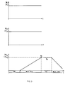
- the minimum size is at any metal / metal oxide layer system according to the invention is established to determine experimentally. Due to the realized degree of oxidation profile was the lifespan of the electrochemical sensor parts compared to those without an oxidation degree profile increased dramatically. As can also be seen from FIG. 3, subsequent to the one produced according to the invention Metal oxide layer in turn a metal layer are stored, so the degree of oxidation again steadily reduced by preferably ramp-shaped Decrease in the mass flow of oxygen m, with which the Layer structure in turn becomes more and more metallic.
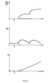
- a further variant of the process control is shown schematically in FIG. 4.
- metal is deposited, for example, onto a metal base in a first time phase T 1 .
- an appropriate evaporation rate r is set and no oxygen is admitted.
- the oxygen mass flow (according to its reference variable W O2 ) is then increased in one step.
- the inertia with which the mass flow of oxygen and in particular the partial pressure in the recipient reacts to a control step is shown, qualitatively exaggerated.
- the rate of vaporized material is guided according to its reference variable W r in such a way that, depending on the prevailing instantaneous mass flow of oxygen, a desired instantaneous oxygen to metal ratio prevails on the surface to be coated in order to achieve the desired degree of oxidation at the moment.
- W r is performed as a function of m.
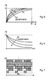
- Layer represented in its structure, as in the procedure 3 or 4 or by controlling the Proportion of excited oxygen is realized. It mean, purely qualitatively, the dark areas the oxidic proportions. From this it can be seen that a constant degree of oxidation transition between metal layer and metal oxide layer with desirable Degree of oxidation takes place, as has been shown, the Adhesion of the layer to the base is essential elevated. It is shown as in the preferred embodiment of the invention Control of the degree of oxidation between metallic and oxidic domain itself Monolayer to monolayer the degree of oxidation changes.
- FIG. 10 which shows a preferred addition to the system according to FIG. 1, the oxygen tank or supply 11 is via a first valve 40, a manometer 41, a second valve, namely a throttle valve 43, to the recipient 1, such as shown in Fig. 1 performed.
- a pump connection with a pump 47 branches off between the first and second valves 40, 43 via a third valve 45.
- This arrangement serves to connect the oxygen supply 11.
- the space between the valves 43, 45 and 40 is ventilated before the tank 11 is connected.
- the tank 11 is then installed, the valves 40, 43, 45 are closed. Thereafter, valve 45 is opened and it is evacuated by means of pump 47 to a final pressure ⁇ 10 -2 mbar, preferably ⁇ 10 -7 mbar.
- the line system between the valves 40, 43, 45 is preferably heated, preferably to at least 200 ° C.
- the valve 45 is closed and gas from the tank 11, after opening the valve 40, is expanded into the line space between the valves 43 and 45.
- the valve 40 is then closed, the valve 45 is opened and this cycle is preferably repeated several times, preferably at least five times, before the oxygen supply 11, after the valve 45 has been closed, is connected in a controlled manner to the vacuum recipient 1 via the valves 40 and 43.
- SiO 2 layers were subsequently grown on Si.
- the evaporation rate measured corresponded to a layer growth on the substrate of less than 0.05 nms -1 (0.5 ⁇ s -1 ), which corresponds to less than 0.1 monolayers per second. This achieved a coating time of 10s per monolayer.
- the time averaged rate fluctuated less than ⁇ 1%. With the oxygen mass flow kept constant, monolayers with an oxidation degree precision of ⁇ 1% could be produced in a controlled manner.
Landscapes
- Chemical & Material Sciences (AREA)
- Chemical Kinetics & Catalysis (AREA)
- Engineering & Computer Science (AREA)
- Materials Engineering (AREA)
- Mechanical Engineering (AREA)
- Metallurgy (AREA)
- Organic Chemistry (AREA)
- Physical Vapour Deposition (AREA)
- Formation Of Insulating Films (AREA)
- Oxygen, Ozone, And Oxides In General (AREA)
- Catalysts (AREA)
Description
- als Dielektrika zur elektronischen Isolation zwischen leitenden Schichten,
- als Dielektrika in Dünnschichtkondensatoren,
- als Schutzschicht zur Kapselung z.B. von integrierten Schaltkreisen,
- als Isolatoren zwischen Supraleitern zur Herstellung schneller Schalter nach dem Josephson-Effekt (Rosenberg, "The Solid State", Oxford University Press, 1988),
- im Schichtaufbau bei Solarzellen,
- im Schichtaufbau bei optischen Bauelementen,
- wegen ihrer Eigenschaft als Festkörper-Elektrolyt, als Gassensoren,
- an elektrochemischen Halbzellen zur EMK-Messung, insbesondere auch für die pH-Messung, dabei auch für ionensensitive Halbleiter-Bauteile, wie als GATE-Schicht für Feldeffekt-Transistoren, sog. ISFET.
- der Hochvakuumbereich zwischen 10-3 und 10-6 mbar,
- der Ultrahoch-Vakuumbereich: Drücke unter 10-6 mbar.
- bei k'/k = 1: die Oxidation ist gesättigt;
- bei k'/k > 1: die Oxidation ist übersättigt, und
- bei k'/k < 1: die Oxidation ist unvollständig.
- Fig. 1
- schematisch, und auch zur Erläuterung des erfindungsgemässen Verfahrens, eine Ausführungsvariante einer erfindungsgemässen Vakuumbehandlungsanlage;
- Fig. 2
- eine weitere Ausführungsvariante des an der Anlage gemäss Fig. 1 eingesetzten Vakuumrezipienten;
- Fig. 3
- schematisch, jeweils über der Zeitachse, beispielsweise den geregelten oder gesteuerten Verlauf der Rate des freigesetzten, insbesondere durch Elektronenstrahlverdampfenfreigesetzten Metalles, der Unterlagentemperatur sowie des Masseflusses eingelassenen Sauerstoffes, letzteres wiederum beispielsweise für das Aufbringen einer erfindungsgemässen Metalloxidschicht auf eine Metallunterlage bzw. das Abdecken der erzeugten Metalloxidschicht, nachfolgend, durch eine Metallabdeckung;
- Fig. 4
- schematisch und ebenfalls qualitativ, analog zu Fig. 3, beispielsweise den geregelten oder gegebenenfalls gesteuerten Verlauf des Masseflusses eingelassenen Sauerstoffes und des Verlaufes der pro Zeiteinheit freigesetzten Metallmenge bzw. elektronenstrahlverdampften Metallmenge sowie einen beispielsweisen resultierenden Verlauf des Verhältnisses (V) von Sauerstoff-Massefluss und Metallrate, wobei der Sauerstoff-Massefluss in grösseren Zeitintervallen verstellt wird und zum Erhalt des erwünschten Verhältnisses die Metallrate nachgeführt wird;
- Fig. 5
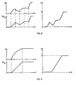
- schematisch und qualitativ, die Abhängigkeit des Oxidationsgrades vom Massefluss des eingelassenen Sauerstoffes, jeweils bei verschiedenen, konstant gehaltenen Raten freigesetzten Metalles, bei einer gegebenen Anlagekonfiguration;
- Fig. 6
- eine Darstellung analog zu Fig. 5 des Oxidationsgrades in Funktion der Rate freigesetzten Metalles bei jeweils konstant gehaltenem Massefluss eingelassenen Sauerstoffes;
- Fig. 7
- schematisch den erfindungsgemässen Aufbau einer erfindungsgemässen Schicht, insbesondere auf einer Metallunterlage, zur Sicherstellung optimaler Schichthaftung;
- Fig. 8 und 9
- je qualitativ, beispielsweise Verläufe von Sauerstoff-Massefluss, daraus resultierend des Oxidationsgrades bei konstant gehaltener Metallfreisetzungsrate und daraus resultierend das Oxidationsgradprofil über der Dicke der sich aufbauenden erfindungsgemässen Schicht;
- Fig. 10
- die Verbindung eines Sauerstoffvorrates mit der Vakuumkammer zur Erläuterung von Reinigungszyklen für das Verbindungsleitungssystem zwischen Vorrat und Vakuumkammer.

Claims (44)
- Verfahren zur Herstellung einer Metalloxidschicht auf einer Unterlage, bei welchem eine Vakuumkammer mindestens auf Hochvakuum-Druckbereich evakuiert wird und Metall in die Vakuumkammer freigesetzt wird, in welche Sauerstoff eingelassen wird, und bei dem die Unterlagstemperatur unter 900°C gehalten wird, dadurch gekennzeichnet, dass zur Herstellung höchstens für Ionen vorgegebener Gattung selektiv durchleitender Schichten die kinetische Energie gegen die Unterlage auftreffender, freigesetzter Metallpartikel höchstens 10eV beträgt und der Oxidationsgrad der Schicht, ausgehend von der Unterlage mit einem zeitlichen Steuerstellraster entsprechend höchstens der Ablagezeit jeweils einer monoatomaren bzw. monomolekularen Schicht erhöht wird.
- Verfahren nach Anspruch 1, dadurch gekennzeichnet, dass das Metall so in die Kammer freigesetzt wird, dass die in der Zeit und über die Freisetzungsfläche gemittelte Freisetzungsrate von einer Metallpartikelquelle nicht mehr als 0,3nms-1, vorzugsweise als 0,1nms-1, vorzugsweise als 0,01nms-1, gar als 0,005nms-1, beträgt.
- Verfahren nach einem der Ansprüche 1 oder 2, dadurch gekennzeichnet, dass die Genauigkeit der über die Zeit und eine Freisetzungsfläche gemittelten Freisetzungsrate des Metalles von einer Metallquelle, bezogen auf einen SOLL-Wert, ≤ 10%, vorzugsweise ≤ 1% ist.
- Verfahren nach einem der Ansprüche 1 bis 3, dadurch gekennzeichnet, dass die Drift der zeitlich und über die Freisetzungsfläche gemittelten Freisetzungsrate des Metalles von einer Metallquelle ≤ 5% in 20 Minuten ist, vorzugsweise ≤ 0,5% in einer Stunde.
- Verfahren nach einem der Ansprüche 1 bis 4, dadurch gekennzeichnet, dass die Unterlage bzw. die sich daran aufbauende Schicht mit dem Sauerstoff und den Metallpartikeln im wesentlichen unreagiert beaufschlagt wird und die Metalloxidschicht in situ gewachsen wird.
- Verfahren nach einem der Ansprüche 1 bis 5, dadurch gekennzeichnet, dass das Metall verdampft, vorzugsweise elektronenstrahlverdampft wird.
- Verfahren nach einem der Ansprüche 1 bis 6, dadurch gekennzeichnet, dass die Rate von einer Metallquelle freigesetzten Metalles gemessen wird.
- Verfahren nach Anspruch 7, dadurch gekennzeichnet, dass die Messung mittels eines Quadrupol-Massenspektrometers erfolgt, z.B. mittels eines QMA400-Massenspektrometers, wie er von der Anmelderin vertrieben wird.
- Verfahren nach einem der Ansprüche 7 oder 8, dadurch gekennzeichnet, dass die Messung der Rate freigesetzten Metalles als IST-Wert-Messung in einem Regelkreis für die Rate freigesetzten Metalles eingesetzt wird und mit der Führungsgrösse des Regelkreises die erwähnte Rate und damit der Oxidationsgrad an der sich aufbauenden Schicht mindestens mit gestellt wird.
- Verfahren nach einem der Ansprüche 7 bis 9, dadurch gekennzeichnet, dass zur Messung der Rate ein materialselektiver Ratesensor mit einer Detektionsempfindlichkeit ≤ 0.01 nms-1 (0,1Ås-1) eingesetzt wird, bevorzugterweise mit einer Detektionsempfindlichkeit ≤ 0.001 nms-1 (0,01Ås-1), bezogen auf die Freisetzung der Metallpartikel an der Metallquelle.
- Verfahren nach einem der Ansprüche 7 bis 10, dadurch gekennzeichnet, dass zur Messung der Rate ein Ratesensor mit einer Ansprechzeit ≤ 100ms, bevorzugterweise ≤ 10ms, bevorzugterweise ≤ 1ms eingesetzt wird.
- Verfahren nach Anspruch 7, dadurch gekennzeichnet, dass die Messung im Raumwinkelbereich erfolgt, unter welchem die Unterlage mit ihrem zu beschichtenden Bereich die Quelle des freigesetzten Metalles sieht.
- Verfahren nach einem der Ansprüche 1 bis 12, dadurch gekennzeichnet, dass die Vakuumkammer auf UHV(Ultra-Hochvakuum)-Restgas-Druckbereich evakuiert wird.
- Verfahren nach einem der Ansprüche 1 bis 13, dadurch gekennzeichnet, dass als Prozessanfangsdruck die Vakuumkammer auf mindestens 10-6 mbar, bevorzugterweise auf mindestens 10-9 mbar evakuiert wird.
- Verfahren nach einem der Ansprüche 7 bis 14, dadurch gekennzeichnet, dass ein zur Messung der freigesetzten Metallrate verwendeter Ratesensor so positioniert ist, dass er von der gleichzeitigen Anwesenheit von Sauerstoff in der Vakuumkammer im wesentlichen nicht beeinflusst wird, dass vorzugsweise Unterlagen und Sauerstoffeinlass über eine Druckstufe vom übrigen Teil der Vakuumkammer abgetrennt werden und im genannten übrigen Teil Metallquelle mit Ratesensor angeordnet werden.
- Verfahren nach einem der Ansprüche 1 bis 15, dadurch gekennzeichnet, dass mindestens eine der folgenden Grössen geregelt wird:Temperatur der Unterlage,freigesetzte Metallmenge pro Zeiteinheit,eingelassene Sauerstoffmenge pro Zeiteinheit bzw. Verhältnis freigesetzter Metallmenge zu eingelassener Sauerstoffmenge je pro Zeiteinheit.
- Verfahren nach einem der Ansprüche 1 bis 16, dadurch gekennzeichnet, dass zwei der drei Grössen Unterlagentemperatur, Menge des pro Zeiteinheit eingelassenen Sauerstoffes, Rate der freigesetzten Metallmenge, mindestens jeweils während vorgegebener Beschichtungszeitabschnitte konstant gehalten werden, vorzugsweise die Unterlagentemperatur und entweder die Menge pro Zeiteinheit eingelassenen Sauerstoffes oder die Metallmenge pro Zeiteinheit, und dass die dritte Grösse jeweils geführt wird.
- Verfahren nach einem der Ansprüche 1 bis 17, dadurch gekennzeichnet, dass die Schicht ein- oder zweiseitig an einer Metalloberfläche anliegend hergestellt wird und hierzu, ausgehend vom Metallbeschichten, ein von der Metallunterlage zunehmender, vorzugsweise stetig zunehmender Oxidationsgrad gestellt wird bzw. gegen eine noch vorzunehmende Metallbeschichtung hin ein abnehmender, vorzugsweise stetig abnehmender Oxidationsgrad.
- Verfahren nach einem der Ansprüche 1 bis 18, dadurch gekennzeichnet, dass entlang der Schichtdicke die Oxidationsgradverteilung durch zeitabhängige Führung mindestens einer der drei Grössen, Temperatur der Unterlage, Rate der freigesetzten Metallmenge, eingelassene Sauerstoffmenge pro Zeiteinheit, gesteuert wird, vorzugsweise die Unterlagentemperatur konstant gehalten wird und eingelassene Sauerstoffmenge pro Zeiteinheit sowie Rate freigesetzten Metalles geführt werden, dabei vorzugsweise die Menge eingelassenen Sauerstoffes in Stellschritten mit grösseren Zeitintervallen, hingegen die Rate freigesetzten Metalles mit einem kleineren Stellzeitraster.
- Verfahren nach einem der Ansprüche 1 bis 19, dadurch gekennzeichnet, dass die Unterlagentemperatur auf maximal 600°C gehalten wird.
- Verfahren nach einem der Ansprüche 1 bis 20, dadurch gekennzeichnet, dass, ausgehend von der Unterlage, die Metalloxidschicht mit einem erwünschten Oxidationsgradprofil aufgebaut wird, indem eine konstante Rate freigesetzten Metalles eingestellt wird und die Menge zugeführten Sauerstoffes so stetig erhöht wird, dass sich nach Massgabe der Metallfreisetzungsrate der Reaktionsgrad von abgelegter, monomolekularer Schicht zur nächsten in vorgebbarer Weise verändert.
- Verfahren nach einem der Ansprüche 1 bis 21, dadurch gekennzeichnet, dass ein Raum, an welchem Sauerstoff eingelassen wird, mit der Unterlage über eine Druckstufe vom übrigen Prozessraum abgetrennt wird.
- Verfahren nach einem der Ansprüche 1 bis 22, dadurch gekennzeichnet, dass der angeregte Sauerstoff in Form von Ozon und/oder Sauerstoffmonomeren und/oder elektronisch angeregtem Sauerstoff und/oder von Ionen zugeführt wird.
- Verfahren nach einem der Ansprüche 1 bis 23, dadurch gekennzeichnet, dass die kinetische Energie des Sauerstoffes oder des angeregten Sauerstoffes nicht höher als 10eV ist.
- Verfahren nach einem der Ansprüche 1 bis 24, dadurch gekennzeichnet, dass der Sauerstoff durch eine Glimmentladung, eine Mikrowellenentladung, induktiv gekoppeltes Plasma und/oder Lichtstrahlung, insbesondere UV-Strahlung, angeregt wird.
- Verfahren nach einem der Ansprüche 1 bis 25, dadurch gekennzeichnet, dass ein Sauerstoffvorrat über ein erstes Ventil vorratseitig und ein zweites Ventil kammerseitig mit der Vakuumkammer verbunden wird, zwischen dem ersten und zweiten Ventil über ein drittes Ventil eine Pumpe angeschlossen wird und vorzugsweise unter Aufheizen des Leitungssystems zwischen den drei Ventilen, vorzugsweise auf mindestens 200°C, bei geschlossenem ersten und zweiten Ventil und geöffnetem dritten Ventil, das Leitungssystem evakuiert wird auf mindestens 10-2mbar, bevorzugterweise auf mindestens 10-7mbar, darnach das dritte Ventil geschlossen wird, das erste geöffnet wird und mit Sauerstoff geflutet wird, und dieser Zyklus vorzugsweise mindestens fünfmal durchgeführt wird, nach dem letzten Fluten wiederum durch Schliessen des ersten Ventils und Oeffnen des dritten das Leitungssystem mit der Pumpe evakuiert wird und erst darnach das zweite Ventil geöffnet wird.
- Verfahren nach einem der Ansprüche 1 bis 26, dadurch gekennzeichnet, dass als Metall Ir freigesetzt, vorzugsweise elektronenstrahlverdampft wird.
- Verfahren nach einem der Ansprüche 1 bis 27, dadurch gekennzeichnet, dass die Menge freigesetzten Metalles mit Stellzeiten von ≤ 100ms, vorzugsweise von ≤ 10ms, vorzugsweise von ≤ 1ms verstellt wird.
- Vakuumbehandlungsanlage zur Ausführung des Verfahrens nach einem der Ansprüche 1 bis 28 mit einer mindestens zur HV-Applikation aufgebauten Vakuumkammer (1) mit Pumpaggregat (17) einer mit einem Sauerstoffvorrat (11) verbundenen Gaseinlassanordnung (7) mit Durchfluss-Stelleranordnung (9), einer beheizbaren Werkstückträgeranordnung (3) mit Temperatur-stelleranordnung (5) sowie mindestens einer Metallpartikelquelle (13) mit Stellgliedanordnung (E13) für die pro Zeiteinheit durch die Quelle freigesetzte Metallpartikelmenge, dadurch gekennzeichnet, dass ein Ratesensor für die Messung der pro Zeiteinheit freigesetzten Metallpartikelmenge vorgesehen ist mit einer Detektionsempfindlichkeit von mindestens 0.01 nms-1 (0,1Å sec-1) und einer Ansprechzeit von höchstens 100msec und dass der Sensor (33) in einem Regelkreis als IST-Wertaufnehmer geschaltet ist und die Metallpartikelquelle darin als Stellglied, wobei der Regelkreis eine über die Zeit und die Freisetzungsfläche der Quelle gemittelte Freisetzungsrate sicherstellt, die höchstens 10% von einer SOLL-Wertvorgabe abweicht.
- Anlage nach Anspruch 29, dadurch gekennzeichnet, dass die Vakuumkammer (1) für UHV-Applikationen ausgelegt ist.
- Anlage nach einem der Ansprüche 29 oder 30, dadurch gekennzeichnet, dass die Metallpartikelquelle eine Verdampfungsquelle, vorzugsweise eine Elektronenstrahl-Verdampfungsquelle ist.
- Anlage nach einem der Ansprüche 29 bis 31, dadurch gekennzeichnet, dass die Metallpartikelquelle für die Abgabe von Metallpartikeln mit einer über die Zeit und über ihre Freigabefläche gemittelten Rate von bis zu mindestens 0,3nms-1, vorzugsweise von mindestens 0,1nms-1, vorzugsweise von mindestens 0,01nms-1, gar von mindestens 0,005nms-1 ausgelegt ist.
- Anlage nach einem der Ansprüche 29 bis 32, dadurch gekennzeichnet, dass die zeitliche Drift der über die Zeit und die Freisetzungsfläche gemittelten freigesetzten Metallpartikelmenge an der Quelle ≤ 5% in 20min, vorzugsweise ≤ 0,5% in 1h, bezogen auf den SOLL-Wert, ist.
- Anlage nach einem der Ansprüche 29 bis 33, dadurch gekennzeichnet, dass der Ratesensor in einem Raumwinkelbereich in der Vakuumkammer angeordnet ist, unter welchem mindestens ein wesentlicher Teil des Werkstückträgers die Freisetzungsfläche der Metallpartikelquelle sieht.
- Anlage nach einem der Ansprüche 29 bis 34, dadurch gekennzeichnet, dass die Detektionsempfindlichkeit höchstens 0.001 nms-1 (0,01Ås-1) ist.
- Anlage nach einem der Ansprüche 29 bis 35, dadurch gekennzeichnet, dass die Ansprechzeit höchstens 10ms, vorzugsweise höchstens lms beträgt.
- Anlage nach einem der Ansprüche 29 bis 36, dadurch gekennzeichnet, dass die Werkstückträgeranordnung und die Gaseinlassanordnung innerhalb einer Druckstufenkammer angeordnet sind, die über mindestens eine Blende mit dem weiteren Innenraum der Vakuumkammer (1) verbunden ist, und dass vorzugsweise der Sensor zur Messung der Rate in der Vakuumkammer ausserhalb der Druckstufenkammer angeordnet ist.
- Anlage nach einem der Ansprüche 29 bis 37, dadurch gekennzeichnet, dass in der Kammer ein Quadrupol-Massenspektrometer, wie ein von der Anmelderin vertriebenes QMA400, zur Messung der von der Partikelquelle freigesetzten Metallpartikelrate vorgesehen ist.
- Anlage nach einem der Ansprüche 29 bis 38, dadurch gekennzeichnet, dass die Durchfluss-Stelleranordnung und/oder die Temperatur-Stelleranordnung und/oder das Ratenstellglied Stelleranordnung eines jeweiligen Regelkreises bilden.
- Anlage nach einem der Ansprüche 29 bis 39, dadurch gekennzeichnet, dass die Durchlass-Stelleranordnung mit einer Steuereinheit (31) verbunden ist, womit, in Funktion der Zeit, die Durchflussmenge an Sauerstoff nach einem vorgebbaren Zeitverlauf gesteuert oder geregelt wird.
- Anlage nach einem der Ansprüche 29 bis 40, dadurch gekennzeichnet, dass die Gaseinlassanordnung über ein erstes Ventil und ein zweites Ventil mit dem Sauerstoffvorrat verbunden ist und zwischen diesen Ventilen, über ein drittes Ventil, eine Pumpe angeschlossen ist.
- Anlage nach einem der Ansprüche 29 bis 41, dadurch gekennzeichnet, dass die Metallpartikelquelle mit Stellzeiten von ≤ 100ms, vorzugsweise von ≤ 10ms, vorzugsweise gar von ≤ 1ms bezüglich der Freisetzungsrate, stellbar ist.
- Mit mindestens einer Metalloxidschicht beschichteter Teil, dadurch gekennzeichnet, dass bei einer Flächenrasterung von mindestens 152mm Rasterfläche mindestens 30% der Rasterfläche mikrorissfrei und höchstens für vorgegebene Ionen selektiv durchlässig ist und der Oxidationsgrad in der Schicht und betrachtet in Dickenausdehnungsrichtung der Schicht von der Unterlage über einen vorgegebenen Dickenbereich stetig zunimmt.
- Teil nach Anspruch 43, dadurch gekennzeichnet, dass mindestens 90% der Fläche höchstens für vorgegebene Ionen selektiv durchlässig ist.
Applications Claiming Priority (2)
| Application Number | Priority Date | Filing Date | Title |
|---|---|---|---|
| CH209592 | 1992-07-02 | ||
| CH2095/92 | 1992-07-02 |
Publications (2)
| Publication Number | Publication Date |
|---|---|
| EP0579018A1 EP0579018A1 (de) | 1994-01-19 |
| EP0579018B1 true EP0579018B1 (de) | 1998-09-30 |
Family
ID=4225773
Family Applications (1)
| Application Number | Title | Priority Date | Filing Date |
|---|---|---|---|
| EP93110252A Expired - Lifetime EP0579018B1 (de) | 1992-07-02 | 1993-06-28 | Verfahren zur Herstellung einer Metalloxidschicht, Vakuumbehandlungsanlage hierfür sowie mit mindestens einer Metalloxidschicht beschichteter Teil |
Country Status (5)
| Country | Link |
|---|---|
| US (1) | US5618575A (de) |
| EP (1) | EP0579018B1 (de) |
| JP (1) | JP3688725B2 (de) |
| AT (1) | ATE171732T1 (de) |
| DE (1) | DE59309018D1 (de) |
Families Citing this family (25)
| Publication number | Priority date | Publication date | Assignee | Title |
|---|---|---|---|---|
| JPH0931645A (ja) * | 1995-07-21 | 1997-02-04 | Sharp Corp | 誘電体薄膜素子の製造方法 |
| US5980974A (en) * | 1996-01-19 | 1999-11-09 | Implant Sciences Corporation | Coated orthopaedic implant components |
| US5855950A (en) * | 1996-12-30 | 1999-01-05 | Implant Sciences Corporation | Method for growing an alumina surface on orthopaedic implant components |
| US6217720B1 (en) * | 1997-06-03 | 2001-04-17 | National Research Council Of Canada | Multi-layer reactive sputtering method with reduced stabilization time |
| US6117487A (en) * | 1998-04-02 | 2000-09-12 | Asahi Denka Kogyo Kabushiki Kaisha | Process for forming metal oxide film by means of CVD system |
| US6106676A (en) * | 1998-04-16 | 2000-08-22 | The Boc Group, Inc. | Method and apparatus for reactive sputtering employing two control loops |
| JP3533950B2 (ja) * | 1998-08-07 | 2004-06-07 | トヨタ自動車株式会社 | 非線形光学シリカ薄膜の製造方法及び非線形光学シリカ素子 |
| CA2281265C (en) * | 1998-09-22 | 2003-12-16 | Toyota Jidosha Kabushiki Kaisha | Method for manufacturing a nonlinear optical thin film |
| US6342278B1 (en) * | 1999-08-04 | 2002-01-29 | General Electric Company | Method for forming a thermal barrier coating by electron beam physical vapor deposition |
| US6478931B1 (en) | 1999-08-06 | 2002-11-12 | University Of Virginia Patent Foundation | Apparatus and method for intra-layer modulation of the material deposition and assist beam and the multilayer structure produced therefrom |
| US6342453B1 (en) * | 1999-12-03 | 2002-01-29 | Applied Materials, Inc. | Method for CVD process control for enhancing device performance |
| US7068544B2 (en) * | 2001-08-30 | 2006-06-27 | Micron Technology, Inc. | Flash memory with low tunnel barrier interpoly insulators |
| US7087954B2 (en) | 2001-08-30 | 2006-08-08 | Micron Technology, Inc. | In service programmable logic arrays with low tunnel barrier interpoly insulators |
| US7476925B2 (en) | 2001-08-30 | 2009-01-13 | Micron Technology, Inc. | Atomic layer deposition of metal oxide and/or low asymmetrical tunnel barrier interploy insulators |
| US7132711B2 (en) * | 2001-08-30 | 2006-11-07 | Micron Technology, Inc. | Programmable array logic or memory with p-channel devices and asymmetrical tunnel barriers |
| US6754108B2 (en) * | 2001-08-30 | 2004-06-22 | Micron Technology, Inc. | DRAM cells with repressed floating gate memory, low tunnel barrier interpoly insulators |
| US7075829B2 (en) | 2001-08-30 | 2006-07-11 | Micron Technology, Inc. | Programmable memory address and decode circuits with low tunnel barrier interpoly insulators |
| US7135734B2 (en) * | 2001-08-30 | 2006-11-14 | Micron Technology, Inc. | Graded composition metal oxide tunnel barrier interpoly insulators |
| US6963103B2 (en) * | 2001-08-30 | 2005-11-08 | Micron Technology, Inc. | SRAM cells with repressed floating gate memory, low tunnel barrier interpoly insulators |
| US6778441B2 (en) * | 2001-08-30 | 2004-08-17 | Micron Technology, Inc. | Integrated circuit memory device and method |
| US7042043B2 (en) | 2001-08-30 | 2006-05-09 | Micron Technology, Inc. | Programmable array logic or memory devices with asymmetrical tunnel barriers |
| US7221586B2 (en) | 2002-07-08 | 2007-05-22 | Micron Technology, Inc. | Memory utilizing oxide nanolaminates |
| JP4030985B2 (ja) * | 2004-06-03 | 2008-01-09 | 月島機械株式会社 | プラズマアシスト蒸着装置及びその制御方法 |
| US7927948B2 (en) | 2005-07-20 | 2011-04-19 | Micron Technology, Inc. | Devices with nanocrystals and methods of formation |
| US8110469B2 (en) | 2005-08-30 | 2012-02-07 | Micron Technology, Inc. | Graded dielectric layers |
Family Cites Families (20)
| Publication number | Priority date | Publication date | Assignee | Title |
|---|---|---|---|---|
| JPS585849B2 (ja) * | 1976-02-20 | 1983-02-02 | 株式会社日立製作所 | 酸化セリウム薄膜の蒸着方法 |
| US4113599A (en) * | 1977-09-26 | 1978-09-12 | Ppg Industries, Inc. | Sputtering technique for the deposition of indium oxide |
| US4172020A (en) * | 1978-05-24 | 1979-10-23 | Gould Inc. | Method and apparatus for monitoring and controlling sputter deposition processes |
| JPS5941510B2 (ja) * | 1979-07-24 | 1984-10-08 | 双葉電子工業株式会社 | 酸化ベリリウム膜とその形成方法 |
| US4379040A (en) * | 1981-01-29 | 1983-04-05 | Ppg Industries, Inc. | Method of and apparatus for control of reactive sputtering deposition |
| JPS60234965A (ja) * | 1984-05-04 | 1985-11-21 | Diesel Kiki Co Ltd | 薄膜製造方法 |
| US4888202A (en) * | 1986-07-31 | 1989-12-19 | Nippon Telegraph And Telephone Corporation | Method of manufacturing thin compound oxide film and apparatus for manufacturing thin oxide film |
| KR910007382B1 (ko) * | 1987-08-07 | 1991-09-25 | 가부시기가이샤 히다찌세이사꾸쇼 | 초전도 재료 및 초전도 박막의 제조방법 |
| US5362711A (en) * | 1987-09-21 | 1994-11-08 | Kanegafuchi Chemical Industry Co., Ltd. | Method for producing single crystal superconducting LnA2 Cu3 O7-x films |
| US4800100A (en) * | 1987-10-27 | 1989-01-24 | Massachusetts Institute Of Technology | Combined ion and molecular beam apparatus and method for depositing materials |
| DE68909618T2 (de) * | 1988-01-09 | 1994-05-05 | Sumitomo Bakelite Co | Verfahren zur Herstellung eines mit einer Dünnschicht aus Metalloxid überzogenen durchsichtigen leitenden Films. |
| JPH01268859A (ja) * | 1988-04-20 | 1989-10-26 | Casio Comput Co Ltd | 透明導電膜の形成方法および形成装置 |
| EP0429536A4 (en) * | 1988-08-19 | 1993-12-15 | Regents Of The University Of Minnesota | Preparation of superconductive ceramic oxides using ozone |
| US4923585A (en) * | 1988-11-02 | 1990-05-08 | Arch Development Corporation | Sputter deposition for multi-component thin films |
| JPH0555645A (ja) * | 1990-06-11 | 1993-03-05 | Mitsubishi Kasei Corp | 薄膜素子 |
| US5227364A (en) * | 1990-06-29 | 1993-07-13 | Sanyo Electric Co., Ltd. | Method of forming patterned oxide superconducting films and Josephson junction devices by using an aqueous alkaline solution |
| WO1994002832A1 (en) * | 1992-07-15 | 1994-02-03 | On-Line Technologies, Inc. | Method and apparatus for monitoring layer processing |
| US5387459A (en) * | 1992-12-17 | 1995-02-07 | Eastman Kodak Company | Multilayer structure having an epitaxial metal electrode |
| US5347157A (en) * | 1992-12-17 | 1994-09-13 | Eastman Kodak Company | Multilayer structure having a (111)-oriented buffer layer |
| US5386798A (en) * | 1993-10-06 | 1995-02-07 | Martin Marietta Energy Systems, Inc. | Method for continuous control of composition and doping of pulsed laser deposited films |
-
1993
- 1993-06-28 DE DE59309018T patent/DE59309018D1/de not_active Expired - Fee Related
- 1993-06-28 AT AT93110252T patent/ATE171732T1/de not_active IP Right Cessation
- 1993-06-28 EP EP93110252A patent/EP0579018B1/de not_active Expired - Lifetime
- 1993-07-02 JP JP16450293A patent/JP3688725B2/ja not_active Expired - Fee Related
-
1995
- 1995-04-21 US US08/427,658 patent/US5618575A/en not_active Expired - Lifetime
Also Published As
| Publication number | Publication date |
|---|---|
| DE59309018D1 (de) | 1998-11-05 |
| JP3688725B2 (ja) | 2005-08-31 |
| JPH0697155A (ja) | 1994-04-08 |
| ATE171732T1 (de) | 1998-10-15 |
| US5618575A (en) | 1997-04-08 |
| EP0579018A1 (de) | 1994-01-19 |
Similar Documents
| Publication | Publication Date | Title |
|---|---|---|
| EP0579018B1 (de) | Verfahren zur Herstellung einer Metalloxidschicht, Vakuumbehandlungsanlage hierfür sowie mit mindestens einer Metalloxidschicht beschichteter Teil | |
| EP0508359B1 (de) | Verfahren und Anlage zur Beschichtung mindestens eines Gegenstandes | |
| EP0885981B1 (de) | Verfahren und Anlage zum Behandeln von Substraten mittels Ionen aus einer Niedervoltbogenentladung | |
| EP0239664B1 (de) | Verfahren zum Herstellen von Silicium und Sauerstoff enthaltenden Schichten | |
| DE2553048A1 (de) | Verfahren und vorrichtung zum erzeugen von verbindungs-duennschichten | |
| EP0909340A1 (de) | Schichtmaterial sowie vorrichtung und verfahren zum herstellen von schichtmaterial | |
| EP0282835B1 (de) | Verfahren und Vorrichtung zur Regelung der reaktiven Schichtabscheidung auf Substraten mittels Magnetronkatoden | |
| EP2036998B1 (de) | Verfahren zur Herstellung einer Multilayerschicht und Vorrichtung zur Durchführung des Verfahrens | |
| DE3430009C2 (de) | Verfahren und Vorrichtung zum Dotieren von Halbleitersubstraten | |
| DE2632093A1 (de) | Verfahren zum herstellen von durchgehenden bohrungen | |
| DE10236896B4 (de) | Vorrichtung und Verfahren zum thermischen Behandeln von Halbleiterwafern | |
| DE3515807A1 (de) | Verfahren zur herstellung eines duennen films | |
| EP1592821B1 (de) | Verfahren zur herstellung einer multilayerschicht und vorrichtung zur durchführung des verfahrens | |
| EP1558782B1 (de) | Vorrichtung und verfahren zum aufdampfen eines hochtemperatursupraleiters im vakuum mit kontinuierlicher materialnachführung | |
| WO2021191285A9 (de) | Verfahren und anlage zur herstellung eines ausgangsmaterials für eine siliziumsolarzelle mit passivierten kontakten | |
| DE102011078243B4 (de) | Herstellungsverfahren für ein elektronisches Bauteil mit einem Schritt zur Einbettung einer Metallschicht | |
| DE69314770T2 (de) | Reaktives Abscheidungsverfahren mittels ionisiertem Cluster-Strahl | |
| CH625911A5 (de) | ||
| EP2113127A1 (de) | Selektiver absorber zur umwandlung von sonnenlicht in wärme, ein verfahren und eine vorrichtung zu dessen herstellung | |
| DE19605315C1 (de) | Verfahren und Einrichtung zur Regelung eines Vakuumbeschichtungsprozesses | |
| DE10341914B4 (de) | Einrichtung zur Herstellung dünner Schichten und Verfahren zum Betreiben der Einrichtung | |
| WO2009030374A1 (de) | Verfahren zur erzeugung eines metallischen rückkontaktes eines halbleiterbauelements, insbesondere einer solarzelle | |
| DE102004060670B4 (de) | Verfahren und Anordnung zur Herstellung hochtemperaturbeständiger Kratzschutzschichten mit geringer Oberflächenrauigkeit | |
| DE102019110203A1 (de) | Verfahren zur Herstellung einer Silikat-Schutzschicht | |
| DE10111515A1 (de) | Plasma-Beschichtungsanlage, Plasma-Beschichtungsverfahren und Verwendung des Verfahrens |
Legal Events
| Date | Code | Title | Description |
|---|---|---|---|
| PUAI | Public reference made under article 153(3) epc to a published international application that has entered the european phase |
Free format text: ORIGINAL CODE: 0009012 |
|
| AK | Designated contracting states |
Kind code of ref document: A1 Designated state(s): AT CH DE FR GB LI NL |
|
| 17P | Request for examination filed |
Effective date: 19940114 |
|
| 17Q | First examination report despatched |
Effective date: 19941214 |
|
| GRAG | Despatch of communication of intention to grant |
Free format text: ORIGINAL CODE: EPIDOS AGRA |
|
| GRAG | Despatch of communication of intention to grant |
Free format text: ORIGINAL CODE: EPIDOS AGRA |
|
| GRAH | Despatch of communication of intention to grant a patent |
Free format text: ORIGINAL CODE: EPIDOS IGRA |
|
| GRAH | Despatch of communication of intention to grant a patent |
Free format text: ORIGINAL CODE: EPIDOS IGRA |
|
| GRAA | (expected) grant |
Free format text: ORIGINAL CODE: 0009210 |
|
| AK | Designated contracting states |
Kind code of ref document: B1 Designated state(s): AT CH DE FR GB LI NL |
|
| PG25 | Lapsed in a contracting state [announced via postgrant information from national office to epo] |
Ref country code: NL Free format text: LAPSE BECAUSE OF FAILURE TO SUBMIT A TRANSLATION OF THE DESCRIPTION OR TO PAY THE FEE WITHIN THE PRESCRIBED TIME-LIMIT Effective date: 19980930 Ref country code: GB Free format text: LAPSE BECAUSE OF FAILURE TO SUBMIT A TRANSLATION OF THE DESCRIPTION OR TO PAY THE FEE WITHIN THE PRESCRIBED TIME-LIMIT Effective date: 19980930 Ref country code: FR Free format text: LAPSE BECAUSE OF FAILURE TO SUBMIT A TRANSLATION OF THE DESCRIPTION OR TO PAY THE FEE WITHIN THE PRESCRIBED TIME-LIMIT Effective date: 19980930 |
|
| REF | Corresponds to: |
Ref document number: 171732 Country of ref document: AT Date of ref document: 19981015 Kind code of ref document: T |
|
| REG | Reference to a national code |
Ref country code: CH Ref legal event code: EP |
|
| REF | Corresponds to: |
Ref document number: 59309018 Country of ref document: DE Date of ref document: 19981105 |
|
| EN | Fr: translation not filed | ||
| NLV1 | Nl: lapsed or annulled due to failure to fulfill the requirements of art. 29p and 29m of the patents act | ||
| GBV | Gb: ep patent (uk) treated as always having been void in accordance with gb section 77(7)/1977 [no translation filed] |
Effective date: 19980930 |
|
| PLBE | No opposition filed within time limit |
Free format text: ORIGINAL CODE: 0009261 |
|
| STAA | Information on the status of an ep patent application or granted ep patent |
Free format text: STATUS: NO OPPOSITION FILED WITHIN TIME LIMIT |
|
| 26N | No opposition filed | ||
| PGFP | Annual fee paid to national office [announced via postgrant information from national office to epo] |
Ref country code: AT Payment date: 20020612 Year of fee payment: 10 |
|
| PG25 | Lapsed in a contracting state [announced via postgrant information from national office to epo] |
Ref country code: AT Free format text: LAPSE BECAUSE OF NON-PAYMENT OF DUE FEES Effective date: 20030628 |
|
| PGFP | Annual fee paid to national office [announced via postgrant information from national office to epo] |
Ref country code: CH Payment date: 20030902 Year of fee payment: 11 |
|
| PG25 | Lapsed in a contracting state [announced via postgrant information from national office to epo] |
Ref country code: LI Free format text: LAPSE BECAUSE OF NON-PAYMENT OF DUE FEES Effective date: 20040630 Ref country code: CH Free format text: LAPSE BECAUSE OF NON-PAYMENT OF DUE FEES Effective date: 20040630 |
|
| REG | Reference to a national code |
Ref country code: CH Ref legal event code: PL |
|
| PGFP | Annual fee paid to national office [announced via postgrant information from national office to epo] |
Ref country code: DE Payment date: 20060622 Year of fee payment: 14 |
|
| PG25 | Lapsed in a contracting state [announced via postgrant information from national office to epo] |
Ref country code: DE Free format text: LAPSE BECAUSE OF NON-PAYMENT OF DUE FEES Effective date: 20080101 |