EP0579018B1 - Procédé de production d'une couche d'oxyde métallique, appareillage de traitement sous vide pour la mise en oeuvre du procédé et article revêtu d'au moins une couche d'oxyde métallique - Google Patents
Procédé de production d'une couche d'oxyde métallique, appareillage de traitement sous vide pour la mise en oeuvre du procédé et article revêtu d'au moins une couche d'oxyde métallique Download PDFInfo
- Publication number
- EP0579018B1 EP0579018B1 EP93110252A EP93110252A EP0579018B1 EP 0579018 B1 EP0579018 B1 EP 0579018B1 EP 93110252 A EP93110252 A EP 93110252A EP 93110252 A EP93110252 A EP 93110252A EP 0579018 B1 EP0579018 B1 EP 0579018B1
- Authority
- EP
- European Patent Office
- Prior art keywords
- metal
- oxygen
- rate
- process according
- released
- Prior art date
- Legal status (The legal status is an assumption and is not a legal conclusion. Google has not performed a legal analysis and makes no representation as to the accuracy of the status listed.)
- Expired - Lifetime
Links
- 229910044991 metal oxide Inorganic materials 0.000 title claims abstract description 24
- 150000004706 metal oxides Chemical class 0.000 title claims abstract description 24
- 238000000034 method Methods 0.000 title claims description 61
- 230000008569 process Effects 0.000 title claims description 46
- 238000004519 manufacturing process Methods 0.000 title claims description 10
- 238000009489 vacuum treatment Methods 0.000 title claims description 8
- 239000002184 metal Substances 0.000 claims abstract description 90
- 229910052751 metal Inorganic materials 0.000 claims abstract description 90
- 229910052760 oxygen Inorganic materials 0.000 claims abstract description 88
- 239000001301 oxygen Substances 0.000 claims abstract description 86
- QVGXLLKOCUKJST-UHFFFAOYSA-N atomic oxygen Chemical compound [O] QVGXLLKOCUKJST-UHFFFAOYSA-N 0.000 claims abstract description 85
- 238000007254 oxidation reaction Methods 0.000 claims abstract description 50
- 230000003647 oxidation Effects 0.000 claims abstract description 49
- 239000000758 substrate Substances 0.000 claims abstract description 27
- 239000002923 metal particle Substances 0.000 claims abstract description 26
- 150000002500 ions Chemical class 0.000 claims abstract description 8
- 238000001704 evaporation Methods 0.000 claims description 21
- 230000008020 evaporation Effects 0.000 claims description 20
- 238000010894 electron beam technology Methods 0.000 claims description 18
- 239000007789 gas Substances 0.000 claims description 18
- 238000000576 coating method Methods 0.000 claims description 12
- 239000011248 coating agent Substances 0.000 claims description 9
- 238000005259 measurement Methods 0.000 claims description 9
- 230000004044 response Effects 0.000 claims description 6
- 239000007787 solid Substances 0.000 claims description 6
- 238000001514 detection method Methods 0.000 claims description 5
- 230000035945 sensitivity Effects 0.000 claims description 5
- 238000011065 in-situ storage Methods 0.000 claims description 4
- 239000000463 material Substances 0.000 claims description 4
- 239000002245 particle Substances 0.000 claims description 4
- 238000005566 electron beam evaporation Methods 0.000 claims description 3
- CBENFWSGALASAD-UHFFFAOYSA-N Ozone Chemical compound [O-][O+]=O CBENFWSGALASAD-UHFFFAOYSA-N 0.000 claims description 2
- 238000006243 chemical reaction Methods 0.000 claims description 2
- 238000009826 distribution Methods 0.000 claims description 2
- 239000000178 monomer Substances 0.000 claims description 2
- 238000009434 installation Methods 0.000 claims 14
- 150000002926 oxygen Chemical class 0.000 claims 2
- 230000005855 radiation Effects 0.000 claims 2
- 230000003247 decreasing effect Effects 0.000 claims 1
- 230000008021 deposition Effects 0.000 claims 1
- 238000009616 inductively coupled plasma Methods 0.000 claims 1
- 230000036962 time dependent Effects 0.000 claims 1
- 239000010410 layer Substances 0.000 description 69
- 230000001105 regulatory effect Effects 0.000 description 6
- 229910052594 sapphire Inorganic materials 0.000 description 4
- 239000010980 sapphire Substances 0.000 description 4
- 238000001883 metal evaporation Methods 0.000 description 3
- 239000002356 single layer Substances 0.000 description 3
- 230000005668 Josephson effect Effects 0.000 description 2
- 239000012298 atmosphere Substances 0.000 description 2
- 230000006835 compression Effects 0.000 description 2
- 238000007906 compression Methods 0.000 description 2
- 238000010276 construction Methods 0.000 description 2
- 238000011109 contamination Methods 0.000 description 2
- 239000003989 dielectric material Substances 0.000 description 2
- 230000000694 effects Effects 0.000 description 2
- 239000010408 film Substances 0.000 description 2
- 229910052741 iridium Inorganic materials 0.000 description 2
- GKOZUEZYRPOHIO-UHFFFAOYSA-N iridium atom Chemical compound [Ir] GKOZUEZYRPOHIO-UHFFFAOYSA-N 0.000 description 2
- 229920006395 saturated elastomer Polymers 0.000 description 2
- 239000004065 semiconductor Substances 0.000 description 2
- 238000003860 storage Methods 0.000 description 2
- 238000012935 Averaging Methods 0.000 description 1
- MYMOFIZGZYHOMD-UHFFFAOYSA-N Dioxygen Chemical compound O=O MYMOFIZGZYHOMD-UHFFFAOYSA-N 0.000 description 1
- -1 Oxygen ion Chemical class 0.000 description 1
- 229910004298 SiO 2 Inorganic materials 0.000 description 1
- 229910009203 Y-Ba-Cu-O Inorganic materials 0.000 description 1
- 238000010521 absorption reaction Methods 0.000 description 1
- 230000009471 action Effects 0.000 description 1
- 239000000853 adhesive Substances 0.000 description 1
- 230000001070 adhesive effect Effects 0.000 description 1
- 239000002390 adhesive tape Substances 0.000 description 1
- 230000015572 biosynthetic process Effects 0.000 description 1
- 230000000903 blocking effect Effects 0.000 description 1
- 239000003990 capacitor Substances 0.000 description 1
- 229910000420 cerium oxide Inorganic materials 0.000 description 1
- 230000008859 change Effects 0.000 description 1
- 239000003795 chemical substances by application Substances 0.000 description 1
- 238000004140 cleaning Methods 0.000 description 1
- 230000001276 controlling effect Effects 0.000 description 1
- 238000005336 cracking Methods 0.000 description 1
- 230000007547 defect Effects 0.000 description 1
- 230000001419 dependent effect Effects 0.000 description 1
- 229910001882 dioxygen Inorganic materials 0.000 description 1
- 238000006056 electrooxidation reaction Methods 0.000 description 1
- 238000005538 encapsulation Methods 0.000 description 1
- 230000005669 field effect Effects 0.000 description 1
- 238000010438 heat treatment Methods 0.000 description 1
- 230000006872 improvement Effects 0.000 description 1
- 239000012535 impurity Substances 0.000 description 1
- 238000009776 industrial production Methods 0.000 description 1
- 238000009413 insulation Methods 0.000 description 1
- 239000012212 insulator Substances 0.000 description 1
- 238000002955 isolation Methods 0.000 description 1
- 238000003698 laser cutting Methods 0.000 description 1
- 230000007774 longterm Effects 0.000 description 1
- 230000007246 mechanism Effects 0.000 description 1
- 150000002739 metals Chemical class 0.000 description 1
- 238000010327 methods by industry Methods 0.000 description 1
- 239000002052 molecular layer Substances 0.000 description 1
- 238000012544 monitoring process Methods 0.000 description 1
- 230000003287 optical effect Effects 0.000 description 1
- BMMGVYCKOGBVEV-UHFFFAOYSA-N oxo(oxoceriooxy)cerium Chemical compound [Ce]=O.O=[Ce]=O BMMGVYCKOGBVEV-UHFFFAOYSA-N 0.000 description 1
- 238000001139 pH measurement Methods 0.000 description 1
- 238000002161 passivation Methods 0.000 description 1
- 238000004886 process control Methods 0.000 description 1
- 239000011241 protective layer Substances 0.000 description 1
- 238000005086 pumping Methods 0.000 description 1
- 230000009257 reactivity Effects 0.000 description 1
- 238000004904 shortening Methods 0.000 description 1
- 239000007784 solid electrolyte Substances 0.000 description 1
- 230000035882 stress Effects 0.000 description 1
- 239000002887 superconductor Substances 0.000 description 1
- 238000012360 testing method Methods 0.000 description 1
- 230000008646 thermal stress Effects 0.000 description 1
- 239000010409 thin film Substances 0.000 description 1
- 230000007704 transition Effects 0.000 description 1
- 239000011364 vaporized material Substances 0.000 description 1
- 239000006200 vaporizer Substances 0.000 description 1
Images
Classifications
-
- C—CHEMISTRY; METALLURGY
- C23—COATING METALLIC MATERIAL; COATING MATERIAL WITH METALLIC MATERIAL; CHEMICAL SURFACE TREATMENT; DIFFUSION TREATMENT OF METALLIC MATERIAL; COATING BY VACUUM EVAPORATION, BY SPUTTERING, BY ION IMPLANTATION OR BY CHEMICAL VAPOUR DEPOSITION, IN GENERAL; INHIBITING CORROSION OF METALLIC MATERIAL OR INCRUSTATION IN GENERAL
- C23C—COATING METALLIC MATERIAL; COATING MATERIAL WITH METALLIC MATERIAL; SURFACE TREATMENT OF METALLIC MATERIAL BY DIFFUSION INTO THE SURFACE, BY CHEMICAL CONVERSION OR SUBSTITUTION; COATING BY VACUUM EVAPORATION, BY SPUTTERING, BY ION IMPLANTATION OR BY CHEMICAL VAPOUR DEPOSITION, IN GENERAL
- C23C14/00—Coating by vacuum evaporation, by sputtering or by ion implantation of the coating forming material
- C23C14/22—Coating by vacuum evaporation, by sputtering or by ion implantation of the coating forming material characterised by the process of coating
- C23C14/54—Controlling or regulating the coating process
-
- C—CHEMISTRY; METALLURGY
- C23—COATING METALLIC MATERIAL; COATING MATERIAL WITH METALLIC MATERIAL; CHEMICAL SURFACE TREATMENT; DIFFUSION TREATMENT OF METALLIC MATERIAL; COATING BY VACUUM EVAPORATION, BY SPUTTERING, BY ION IMPLANTATION OR BY CHEMICAL VAPOUR DEPOSITION, IN GENERAL; INHIBITING CORROSION OF METALLIC MATERIAL OR INCRUSTATION IN GENERAL
- C23C—COATING METALLIC MATERIAL; COATING MATERIAL WITH METALLIC MATERIAL; SURFACE TREATMENT OF METALLIC MATERIAL BY DIFFUSION INTO THE SURFACE, BY CHEMICAL CONVERSION OR SUBSTITUTION; COATING BY VACUUM EVAPORATION, BY SPUTTERING, BY ION IMPLANTATION OR BY CHEMICAL VAPOUR DEPOSITION, IN GENERAL
- C23C14/00—Coating by vacuum evaporation, by sputtering or by ion implantation of the coating forming material
- C23C14/0021—Reactive sputtering or evaporation
-
- H—ELECTRICITY
- H01—ELECTRIC ELEMENTS
- H01J—ELECTRIC DISCHARGE TUBES OR DISCHARGE LAMPS
- H01J2237/00—Discharge tubes exposing object to beam, e.g. for analysis treatment, etching, imaging
- H01J2237/18—Vacuum control means
- H01J2237/182—Obtaining or maintaining desired pressure
-
- H—ELECTRICITY
- H01—ELECTRIC ELEMENTS
- H01J—ELECTRIC DISCHARGE TUBES OR DISCHARGE LAMPS
- H01J2237/00—Discharge tubes exposing object to beam, e.g. for analysis treatment, etching, imaging
- H01J2237/20—Positioning, supporting, modifying or maintaining the physical state of objects being observed or treated
- H01J2237/2001—Maintaining constant desired temperature
-
- H—ELECTRICITY
- H01—ELECTRIC ELEMENTS
- H01J—ELECTRIC DISCHARGE TUBES OR DISCHARGE LAMPS
- H01J2237/00—Discharge tubes exposing object to beam, e.g. for analysis treatment, etching, imaging
- H01J2237/30—Electron or ion beam tubes for processing objects
- H01J2237/31—Processing objects on a macro-scale
- H01J2237/3132—Evaporating
Definitions
- the present invention relates to a method according to the The preamble of claim 1, a vacuum treatment plant for Execution of said method according to that of claim 29 and one with at least one metal oxide layer coated part according to claim 43.
- the term "metal oxide” the oxides of the semiconductors should also be understood.
- microcracks can in all cases cancel the function of the oxide layer. For example when used as a pH sensor layer due to such microcracks the layer shorted.
- EP-A-0 302 506 it is known in the manufacture electrically superconducting layers the evaporation release rate to regulate and the energy on the to be coated Oxygen ion striking substrate as deep as possible to keep.
- the substrate temperature is kept at 800 ° C.
- the aim of the present invention is to initiate a method to propose the type mentioned, by means of which the mentioned Metal oxide layers can be manufactured industrially and the mentioned requirements regarding micro cracks, Impurity and adhesive strength are sufficient, as well as a Vacuum treatment plant, by means of which the named Layers can be produced, as well as, further, parts, which are manufactured industrially to meet the requirements mentioned.
- the metal continues according to the wording released from claim 2 in the vacuum chamber.
- Claim 3 proceeded, which allowed the release rate to guide exactly, and enables the mentioned Degree of oxidation profile, according to the simultaneously supplied amount of oxygen per unit of time, according to a given target profile to realize.
- the whole should be understood as the release area Area of a metal particle source from within metal particles released during the coating time will.
- the metal is preferably according to the wording of claim 6 released by evaporation, thereby preferably by electron beam evaporation Process, particularly in the one to be described Way is exactly manageable.
- the amount of metal is preferably after Wording of claim 7 during the coating process measured.
- the measurement in the solid angle range under which the underlay with its area to be coated Source of the released metal sees. So that exists essentially proportionality between the Quantity of metal per unit of time determined at the measuring location and the amount of metal deposited on the pad per unit of time and area.
- the measurement is preferably carried out after the Wording of claim 8 made and further following the wording of claim 9. With that, at constant amount of oxygen supplied per unit of time, the degree of oxidation at the building up Shift regulated or regulated or at Providing the amount of oxygen supplied per unit of time posed with.
- the preferred response time corresponds to this ⁇ msec especially the flight time of electron-beam vaporized particles in the mentioned maximum kinetic energy of approx. 10 eV above a distance of 50cm between the source and one mounted in this regard at a distance of 50cm coating base.
- the one for measuring the Rate released metal rate sensor used arranged according to the wording of claim 15 this preferably realized by providing a pressure stage between metal source and rate sensor on the one hand and oxygen intake and pad on the other.
- Two of the three sizes are preferably Document temperature per unit of time and per unit of time amount of oxygen admitted or rate of release, kept constant.
- the metal oxide layer mentioned should it be one or two sided on a metal surface be made to fit, whereby then preferably selected the same metal as metal from which the oxide of the layer is also formed becomes. Also responsible for the formation of micro cracks is, as has been mentioned, the liability of the invention prepared metal oxide layer the document, in the present case on the minimum a called metal surface.
- the degree of oxidation the building layer in particular by keeping the surface temperature constant and by setting the amount of oxygen admitted per unit of time carried out at longer intervals, whereby, in a smaller positioning time grid, the rate of metal released is set.
- adjustment steps and adjustment times of the released Metal rate especially in the proposed evaporation rate control to be described later, are much finer or shorter than Positioning times of gas inflow regulations, taking into account their inertia caused by supply lines etc.
- excited oxygen can be used in Form of ozone and / or oxygen monomer and / or electronically excited oxygen or ions.
- the kinetic energy not even of the excited oxygen be more than 10 eV, so that only the oxidation yield to increase and thereby no undefined Influencing first the document, then the To give layer surface properties.
- a vacuum treatment plant to carry out the explained Procedure is according to the wording of claim 29 trained, preferred variants this plant claims 30 to 42.
- parts coated according to the invention can be produced with an unexpectedly low reject rate.
- parts coated with at least one metal oxide layer can be produced at the same time, whereby, given a given surface area of the individual parts of at least 15 mm 2, at least 30%, preferably at least 40% of the parts are selectively conductive for a maximum of specified ions and are therefore usable as sensors. There is even a yield higher than 90%; At the same time, the life of the parts, for example as sensors, is significantly increased.
- the yield percentages mentioned relate to surface areas of the coating of at least 15 mm 2 .
- a yield of 90% means that 1350mm 2 of 1500mm 2 of coated surface are free of microcracks.
- the parts can already be coated as such or only as a "large substrate", which afterwards, such as. through a laser cutting process, into the individual parts to be used is divided.
- an electron beam evaporator is used as a metal source and this for obtaining highest precision regarding guidance, preferably made by means of an electron beam source will, as in the published publications the applicant DE-OS-39 21 040 and 39 29 475 is described or after those described there Control procedures, these two documents are hereby as an integral part of the present description explained.
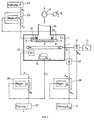
- FIG. 1 A preferred embodiment variant is shown schematically in FIG a vacuum treatment plant according to the invention shown, based on which also the inventive Procedure to be explained.
- a movable or, as shown, stationary workpiece carrier 3 is provided in a known manner.
- the workpiece carrier 3 is, as shown schematically with the heating element 5, heated.
- a gas shower 7 is provided, preferably designed as an annular gas shower, as shown, which is connected via a mass flow actuator 9 to an oxygen storage tank 11.
- the actuator 9 can be controlled at an input E 9 .
- the workpiece carrier 3 opposite is an electron beam evaporator source with electron beam generator 13 intended.
- the electron beam evaporator unit 13 has a control input E 13 , by means of which the evaporation rate r, defined as per unit time and averaged over the release or evaporation surface of the evaporated amount of evaporated metal, can be set sufficiently quickly and with sufficient precision that as will be described later, this rate can be changed from deposited molecular layer to the next as desired.
- an evaporation rate averaged over time of less than 0.3nms -1 , preferably 0.1nms -1 , preferably 0.01nms -1 , even 0.005nms -1 can be set on the electron beam evaporator unit 13, wherein this rate must of course not disappear.
- the electron beam evaporator unit 13 an average evaporation rate with a Accuracy of ⁇ 10%, preferably at most ⁇ 3%, preferably not more than ⁇ 1% will.
- the long-term drift on the electron beam evaporator unit 13 adjustable middle Evaporation rate should be minimal because the processes mentioned here due to the slow Layer construction are relatively lengthy processes.
- This drift of the averaged rate is preferably less than 5% of the TARGET value in 20 minutes even more preferably less than or equal to 0.5% in one Hour.
- r is the current rate and T is the averaging time of preferably 10 seconds.
- a pump connection 15 for evacuation of the vacuum recipient 1 and, if necessary, with the Control of the oxygen partial pressure in the process room P provided.
- the pump connection 15 is with a Vacuum pump 17 connected, the pumping power at one Unit 19 is adjustable.
- a temperature sensor 21 is provided, the output signal of which either serves to monitor the workpiece carrier temperature or, preferably, and as shown, as an actual temperature value signal X ⁇ on a control circuit, shown schematically at 23, is led.
- the temperature control circuit 23 is guided by a temperature control unit 25 and acts with an actuating signal corresponding to the increased control difference S ⁇ on the control input E 3 for the workpiece holder temperature ⁇ .
- the workpiece temperature is set to a maximum of 900 ° C, preferably to a maximum of 600 ° C.
- gas inlet arrangement 7 there is also a sensor unit 27 connected by means of which the mass flow of oxygen m is measured. Instead of it can also be the partial pressure of oxygen in the chamber be measured.
- Gas mass flow m gives the oxygen partial pressure in the recipient according to the requirements of the vacuum pump 17 set suction power and according to the oxygen consumed by oxidation reaction.
- the output signal of the sensor unit 27 is therefore either used for control purposes or, and this is preferably and as shown, fed as a measured manipulated variable signal X m to a control circuit 29, which acts on the input E 9 of the actuator unit 9 with an actuating signal S m .
- a flow quantity guide unit 31 By means of a flow quantity guide unit 31, the gas quantity supplied to the recipient 1 per unit time, the gas mass flow m, is guided in a regulating sense.
- a metal-selective rate sensor 33 is provided, preferably in an angular range at which a workpiece O on the workpiece carrier 3 sees the metal source, and consequently the evaporated surface - release surface - on the evaporation unit 13.
- the rate sensor preferably has a detection sensitivity 0.01 0.01 nms -1 (0.1 ⁇ s -1 ), preferably even ⁇ 0.001 nms -1 (0.01 ⁇ s -1 ).
- the rate sensor 33 used furthermore preferably has a response time (step response) 100 100 ms, preferably Facebookzug 10 ms or preferably even 1 1 ms. The latter corresponds to the flight time of evaporated metal particles with a kinetic energy ⁇ 10 eV in a system configuration as shown, if a distance of approx. 50 cm is maintained between the evaporated metal surface and the workpiece surface to be coated.
- quadrupole mass spectrometer as a sensor 33 used as a mass spectrometer QMA400, such as it is distributed by the applicant.
- the sensitive rate sensor 33 by oxygen gas being affected.
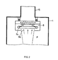
- the gas shower 7a arranged within a compression chamber 8, with aperture 8a.
- the pressure inside the compression chamber 8 is done by injecting oxygen compared to the pressure in the rest of the process chamber P increased, this pressure difference, at least to Part, is taken up by the action of the aperture 8a. This prevents significant amounts of oxygen get into the area of the sensor 33.
- the quantity measured by the sensor 33 and dependent on the instantaneous evaporation rate prevailing over the evaporation surface is either used for control purposes for the evaporation rate or, and preferably as shown, is fed as a measured control quantity X r to a control circuit 35, the latter with the control signal S r at the input E 13 of the electron beam evaporator unit 13 represents the instantaneous evaporation rate.
- the control loop is guided by a rate management unit 37.
- the metal particle source such as preferably an electron beam evaporator according to DE-OS-39 21 040, preferably has positioning times for the rate of at most 100ms, preferably of at most 10ms or even from at most lms.
- a process is carried out as follows on the system, as is shown schematically in FIG. 1:
- the vacuum recipient 1 is evacuated to high vacuum, preferably ultra-high vacuum, by means of the vacuum pump 17, ie to a starting pressure 10 10 -6 mbar preferably ⁇ 10 -9 mbar. This minimizes the contamination of the process gas, the oxygen, which is subsequently fed in, with residual gas.
- Metal evaporates and, via the gas inlet arrangement 7 or 7a, oxygen admitted into the vacuum recipient 1.
- the ratio of the per unit time amount of oxygen admitted, i.e. the mass flow of oxygen m, to the mean evaporated per unit of time Amount of metal whose rate r is chosen such that the evaporated metal preferably primarily on the pad, i.e. the workpiece surface to be coated O homogeneously distributed with a given Degree of oxidation, oxidized.
- the substrate temperature ⁇ minimal, preferably below 900 °, preferably kept below or equal to 600 °.
- the partial pressure was used in the production of the layer of oxygen and therefore m during the coating process kept constant, as well Rate r.
- an Ir 2 O 3 layer was evaporated onto an Ir pad, on the one hand, and on the other hand onto a sapphire pad.
- the evaporation rate r was constantly controlled and the temperature of the layer base, as in the example mentioned above, was set to 600 ° C.
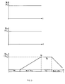
- a shortening of the ramp duration can result from process engineering Reasons, namely time and throughput, are shortened until about 5 minutes.
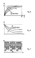
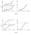
- the minimum size is at any metal / metal oxide layer system according to the invention is established to determine experimentally. Due to the realized degree of oxidation profile was the lifespan of the electrochemical sensor parts compared to those without an oxidation degree profile increased dramatically. As can also be seen from FIG. 3, subsequent to the one produced according to the invention Metal oxide layer in turn a metal layer are stored, so the degree of oxidation again steadily reduced by preferably ramp-shaped Decrease in the mass flow of oxygen m, with which the Layer structure in turn becomes more and more metallic.
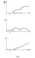
- a further variant of the process control is shown schematically in FIG. 4.
- metal is deposited, for example, onto a metal base in a first time phase T 1 .
- an appropriate evaporation rate r is set and no oxygen is admitted.
- the oxygen mass flow (according to its reference variable W O2 ) is then increased in one step.
- the inertia with which the mass flow of oxygen and in particular the partial pressure in the recipient reacts to a control step is shown, qualitatively exaggerated.
- the rate of vaporized material is guided according to its reference variable W r in such a way that, depending on the prevailing instantaneous mass flow of oxygen, a desired instantaneous oxygen to metal ratio prevails on the surface to be coated in order to achieve the desired degree of oxidation at the moment.
- W r is performed as a function of m.
- Layer represented in its structure, as in the procedure 3 or 4 or by controlling the Proportion of excited oxygen is realized. It mean, purely qualitatively, the dark areas the oxidic proportions. From this it can be seen that a constant degree of oxidation transition between metal layer and metal oxide layer with desirable Degree of oxidation takes place, as has been shown, the Adhesion of the layer to the base is essential elevated. It is shown as in the preferred embodiment of the invention Control of the degree of oxidation between metallic and oxidic domain itself Monolayer to monolayer the degree of oxidation changes.
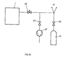
- FIG. 10 which shows a preferred addition to the system according to FIG. 1, the oxygen tank or supply 11 is via a first valve 40, a manometer 41, a second valve, namely a throttle valve 43, to the recipient 1, such as shown in Fig. 1 performed.
- a pump connection with a pump 47 branches off between the first and second valves 40, 43 via a third valve 45.
- This arrangement serves to connect the oxygen supply 11.
- the space between the valves 43, 45 and 40 is ventilated before the tank 11 is connected.
- the tank 11 is then installed, the valves 40, 43, 45 are closed. Thereafter, valve 45 is opened and it is evacuated by means of pump 47 to a final pressure ⁇ 10 -2 mbar, preferably ⁇ 10 -7 mbar.
- the line system between the valves 40, 43, 45 is preferably heated, preferably to at least 200 ° C.
- the valve 45 is closed and gas from the tank 11, after opening the valve 40, is expanded into the line space between the valves 43 and 45.
- the valve 40 is then closed, the valve 45 is opened and this cycle is preferably repeated several times, preferably at least five times, before the oxygen supply 11, after the valve 45 has been closed, is connected in a controlled manner to the vacuum recipient 1 via the valves 40 and 43.
- SiO 2 layers were subsequently grown on Si.
- the evaporation rate measured corresponded to a layer growth on the substrate of less than 0.05 nms -1 (0.5 ⁇ s -1 ), which corresponds to less than 0.1 monolayers per second. This achieved a coating time of 10s per monolayer.
- the time averaged rate fluctuated less than ⁇ 1%. With the oxygen mass flow kept constant, monolayers with an oxidation degree precision of ⁇ 1% could be produced in a controlled manner.
Landscapes
- Chemical & Material Sciences (AREA)
- Chemical Kinetics & Catalysis (AREA)
- Engineering & Computer Science (AREA)
- Materials Engineering (AREA)
- Mechanical Engineering (AREA)
- Metallurgy (AREA)
- Organic Chemistry (AREA)
- Physical Vapour Deposition (AREA)
- Formation Of Insulating Films (AREA)
- Oxygen, Ozone, And Oxides In General (AREA)
- Catalysts (AREA)
Claims (44)
- Procédé pour la fabrication d'une couche d'oxyde métallique sur un substrat, selon lequel on fait le vide dans une chambre à vide au moins jusqu'à la plage de pression de vide poussé, et du métal est libéré dans la chambre à vide, dans laquelle de l'oxygène est introduit, et selon lequel la température du substrat est maintenue au-dessous de 900°C,
caractérisé en ce que pour la fabrication de couches sélectivement conductrices au maximum pour des ions d'un type prédéfini, l'énergie cinétique de particules métalliques libérées arrivant sur le substrat est au maximum de 10 eV et le degré d'oxydation de la couche est augmenté, à partir du substrat, selon une grille de commande dans le temps, au maximum en fonction du temps de dépôt d'une couche monoatomique ou monomoléculaire. - Procédé selon la revendication 1, caractérisé en ce que le métal est libéré dans la chambre de telle sorte que la vitesse de libération moyenne dans le temps et sur la surface de libération, à partir d'une source de particules métalliques, ne dépasse pas 0,3 nms-1, de préférence 0,1 nms-1 et plus spécialement 0,01 nms-1, voire 0,005 nms-1.
- Procédé selon la revendication 1 ou 2, caractérisé en ce que la précision de la vitesse de libération moyenne du métal, dans le temps et sur une surface de libération, à partir d'une source métallique, est ≤ 10 %, de préférence ≤ 1 %, par rapport à une valeur théorique.
- Procédé selon l'une des revendications 1 à 3, caractérisé en ce que la dérive de la vitesse de libération moyenne du métal, dans le temps et sur la surface de libération, à partir d'une source métallique, est ≤ 5 % en 20 minutes, de préférence ≤ 0,5 % en 1 heure.
- Procédé selon l'une des revendications 1 à 4, caractérisé en ce qu'on amène sur le substrat ou la couche qui se forme sur celui-ci l'oxygène et les particules métalliques essentiellement à l'état non réagi, et la couche d'oxyde métallique se forme in situ.
- Procédé selon l'une des revendications 1 à 5, caractérisé en ce que le métal est évaporé, de préférence à l'aide d'un faisceau d'électrons.
- Procédé selon l'une des revendications 1 à 6, caractérisé en ce qu'on mesure la vitesse du métal libéré à partir d'une source métallique.
- Procédé selon la revendication 7, caractérisé en ce que la mesure a lieu à l'aide d'un spectromètre de masse quadripolaire, par exemple à l'aide d'un spectromètre de masse QMA400 vendu par le déposant.
- Procédé selon la revendication 7 ou 8, caractérisé en ce que la mesure de la vitesse du métal libéré est utilisée comme mesure de valeur réelle dans un circuit de régulation pour la vitesse du métal libéré, et la vitesse mentionnée et, ainsi, le degré d'oxydation sur la couche qui se forme sont au moins réglés avec la grandeur de référence du circuit de régulation.
- Procédé selon l'une des revendications 7 à 9, caractérisé en ce qu'on utilise, pour mesurer la vitesse, un détecteur de vitesse à sélection de matériau qui présente une sensibilité de détection ≤ 0,01 nms-1 (0,1 Ås-1), de préférence ≤ 0,001 nms-1 (0,01 Ås-1) par rapport à la libération des particules métalliques au niveau de la source métallique.
- Procédé selon l'une des revendications 7 à 10, caractérisé en ce qu'on utilise, pour mesurer la vitesse, un détecteur de vitesse qui présente un temps de réaction ≤ 100 ms, de préférence ≤ 10 ms et plus spécialement ≤ 1 ms.
- Procédé selon la revendication 7, caractérisé en ce que la mesure a lieu dans la zone d'angle solide dans laquelle le substrat, avec sa zone à revêtir, est à portée optique de la source du métal libéré.
- Procédé selon l'une des revendications 1 à 12, caractérisé en ce qu'on fait le vide dans la chambre à vide jusqu'à la plage de pression de gaz résiduel d'ultravide.
- Procédé selon l'une des revendications 1 à 13, caractérisé en ce que, comme pression initiale de procédé, on fait le vide dans la chambre à vide jusqu'à au moins 10-6 mbar, de préférence au moins 10-9 mbar.
- Procédé selon l'une des revendications 7 à 14, caractérisé en ce qu'un détecteur de vitesse utilisé pour la mesure de la vitesse de métal libéré est positionné de telle sorte qu'il ne soit pratiquement pas influencé par la présence simultanée d'oxygène dans la chambre à vide, et en ce que les substrats et l'orifice d'admission d'oxygène sont de préférence séparés de la partie restante de la chambre à vide par l'intermédiaire d'un palier de pression, et la source métallique est disposée avec le détecteur de vitesse dans ladite partie restante.
- Procédé selon l'une des revendications 1 à 15, caractérisé en ce qu'on règle l'une au moins des grandeurs suivantes :température du substrat,quantité de métal libéré par unité de temps,quantité d'oxygène introduit par unité de temps ou rapport de la quantité de métal libéré à la quantité d'oxygène introduit, par unité de temps.
- Procédé selon l'une des revendications 1 à 16, caractérisé en ce que deux des trois grandeurs définies par la température du substrat, la quantité d'oxygène introduit par unité de temps et la vitesse de la quantité de métal libéré sont maintenues constantes au moins pendant des périodes d'application de revêtement prédéfinies, de préférence la température du substrat et soit la quantité d'oxygène introduit par unité de temps, soit la quantité de métal par unité de temps, et en ce que la troisième grandeur est commandée.
- Procédé selon l'une des revendications 1 à 17, caractérisé en ce que la couche est fabriquée unilatéralement ou bilatéralement contre une surface métallique et à cet effet, à partir de l'application d'un revêtement métallique, on règle un degré d'oxydation qui augmente, de préférence de manière continue, à partir du substrat métallique, ou un degré d'oxydation qui va en diminuant, de préférence de manière continue, en direction d'un revêtement métallique qui doit encore être appliqué.
- Procédé selon l'une des revendications 1 à 18, caractérisé en ce que le long de l'épaisseur de couche, on commande la répartition de degré d'oxydation grâce à un contrôle dans le temps de l'une au moins des trois grandeurs (température du substrat, vitesse de la quantité de métal libéré et quantité d'oxygène introduit par unité de temps), on maintient de préférence la température du substrat constante et on contrôle la quantité d'oxygène introduit par unité de temps ainsi que la vitesse du métal libéré, la quantité d'oxygène introduit étant contrôlée par phases de réglage présentant des intervalles de temps assez longs, tandis que la vitesse du métal libéré est contrôlée avec une trame de temps de réglage plus petite.
- Procédé selon l'une des revendications 1 à 19, caractérisé en ce que la température du substrat est maintenue à 600°C maximum.
- Procédé selon l'une des revendications 1 à 20, caractérisé en ce que, à partir du substrat, on forme la couche d'oxyde métallique avec un profil de degré d'oxydation souhaité, en réglant une vitesse constante pour le métal libéré et en augmentant continuellement la quantité d'oxygène amené, de telle sorte que le degré de réaction varie d'une manière prédéfinie d'une couche monomoléculaire déposée à l'autre, en fonction de la vitesse de libération de métal.
- Procédé selon l'une des revendications 1 à 21, caractérisé en ce qu'un espace dans lequel l'oxygène est introduit et qui contient le substrat est séparé du reste de l'espace de traitement par un palier de pression.
- Procédé selon l'une des revendications 1 à 22, caractérisé en ce que l'oxygène excité est amené sous forme d'ozone et/ou de monomères d'oxygène et/ou d'oxygène excité par voie électronique et/ou d'ions.
- Procédé selon l'une des revendications 1 à 23, caractérisé en ce que l'énergie cinétique de l'oxygène ou de l'oxygène activé n'est pas supérieure à 10 eV.
- Procédé selon l'une des revendications 1 à 24, caractérisé en ce que l'oxygène est activé par une décharge lumineuse, une décharge de micro-ondes, un plasma à couplage inductif et/ou un rayonnement lumineux, en particulier ultraviolet.
- Procédé selon l'une des revendications 1 à 25, caractérisé en ce qu'on relie une réserve d'oxygène à la chambre à vide grâce à une première soupape, côté réserve, et à une deuxième soupape, côté chambre ; on raccorde une pompe entre les première et deuxième soupape grâce à une troisième soupape et on fait le vide dans le système de conduites jusqu'à au moins 10-2 mbar, de préférence au moins 10-7 mbar, en chauffant de préférence le système de conduites entre les trois soupapes, de préférence à au moins 200°C, alors que les première et deuxième soupapes sont fermées et la troisième soupape ouverte ; puis on ferme la troisième soupape, on ouvre la première et on remplit d'oxygène ; et on effectue ce cycle de préférence au moins cinq fois ; après le dernier remplissage, on fait à nouveau le vide dans le système de conduites à l'aide de la pompe, en fermant la première soupape et en ouvrant la troisième ; et à ce moment seulement, on ouvre la deuxième soupape.
- Procédé selon l'une des revendications 1 à 26, caractérisé en ce que le métal libéré est Ir, et il est de préférence évaporé par faisceau d'électrons.
- Procédé selon l'une des revendications 1 à 27, caractérisé en ce que la quantité de métal libéré est ajustée avec des temps de réglage ≤ 100 ms, de préférence ≤ 10 ms et plus spécialement ≤ 1 ms.
- Installation de traitement sous vide pour la mise en oeuvre du procédé selon l'une des revendications 1 à 28, comprenant une chambre à vide (1) qui est construite au moins pour une application à vide poussé et qui comporte un groupe moto-pompe (17) d'un dispositif d'admission de gaz (7) relié à une réserve d'oxygène (11) et pourvu d'un dispositif de réglage de débit (9), un dispositif porte-pièce (3) qui est apte à être chauffé et qui comporte un dispositif de réglage de température (5), et au moins une source de particules métalliques (13) qui comporte un dispositif formant composant de réglage (E13) pour la quantité de particules métalliques libérée par unité de temps par la source,
caractérisée en ce qu'il est prévu un détecteur de vitesse pour mesurer la quantité de particules métalliques libérées par unité de temps, qui présente une sensibilité de détection d'au moins 0,01 nms-1 (0,1 Ås-1) et un temps de réaction de 100 ms maximum, et en ce que le détecteur (33) est monté dans un circuit de régulation comme capteur de valeurs réelles, et la source de particules métalliques comme composant de réglage, le circuit de régulation garantissant une vitesse de libération moyenne dans le temps et sur la surface de libération de la source qui diffère de 10 % maximum d'une valeur théorique prédéfinie. - Installation selon la revendication 29, caractérisée en ce que la chambre à vide (1) est conçue pour des applications à ultravide.
- Installation selon la revendication 29 ou 30, caractérisée en ce que la source de particules métalliques est une source d'évaporation, de préférence une source d'évaporation par faisceau d'électrons.
- Installation selon l'une des revendications 29 à 31, caractérisée en ce que la source de particules métalliques est conçue pour émettre des particules métalliques à une vitesse moyenne dans le temps et sur sa surface de libération qui va jusqu'à au moins 0,3 nms-1, de préférence au moins 0,1 nms-1 et plus spécialement au moins 0,01 nms-1, voire au moins 0,005 nms-1.
- Installation selon l'une des revendications 29 à 32, caractérisée en ce que la dérive dans le temps de la quantité moyenne, dans le temps et sur la surface de libération, de particules métalliques libérées au niveau de la source est ≤ 5 % en 20 minutes, de préférence ≤ 0,5 % en 1 heure, par rapport à la valeur théorique.
- Installation selon l'une des revendications 29 à 33, caractérisée en ce que le détecteur de vitesse est disposé dans la chambre à vide dans une zone d'angle solide dans laquelle le substrat, avec au moins une partie essentielle du porte-pièce est à portée optique de la surface de libération de la source de particules métalliques.
- Installation selon l'une des revendications 29 à 34, caractérisée en ce que la sensibilité de détection est de 0,001 nms-1 (0,01 Ås-1) maximum.
- Installation selon l'une des revendications 29 à 35, caractérisée en ce que le temps de réaction est de 10 ms maximum, de préférence de 1 ms maximum.
- Installation selon l'une des revendications 29 à 36, caractérisée en ce que le dispositif porte-pièce et le dispositif d'admission de gaz sont disposés à l'intérieur d'une chambre à paliers de pression qui est reliée grâce à au moins un diaphragme à la suite de l'espace intérieur de la chambre à vide (1), et en ce que le détecteur prévu pour mesurer la vitesse est disposé de préférence dans la chambre à vide à l'extérieur de la chambre à paliers de pression.
- Installation selon l'une des revendications 29 à 37, caractérisée en ce qu'il est prévu, dans la chambre, un spectromètre de masse quadripolaire tel qu'un QMA400 vendu par le déposant pour mesurer la vitesse de particules métalliques libérées par la source de particules.
- Installation selon l'une des revendications 29 à 38, caractérisée en ce que le dispositif de réglage de débit et/ou le dispositif de réglage de température et/ou le composant de réglage de vitesse forment le dispositif de réglage d'un circuit de régulation correspondant.
- Installation selon l'une des revendications 29 à 39, caractérisée en ce que le dispositif de réglage de débit est relié à une unité de commande (31), moyennant quoi, en fonction du temps, le débit d'oxygène est commandé ou régulé suivant une courbe dans le temps apte à être prédéfinie.
- Installation selon l'une des revendications 29 à 40, caractérisée en ce que le dispositif d'admission de gaz est relié à la réserve d'oxygène par une première et une deuxième soupape, et une pompe est raccordée entre ces soupapes grâce à une troisième soupape.
- Installation selon l'une des revendications 29 à 41, caractérisée en ce que la source de particules métalliques est apte à être réglée, pour la vitesse de libération, à des temps de réglage ≤ 100 ms, de préférence ≤ 10 ms et plus spécialement ≤ 1 ms.
- Pièce revêtue d'au moins une couche d'oxyde métallique, caractérisée en ce que pour un quadrillage de surface d'au moins 15mm2 de surface quadrillée, au moins 30% de ladite surface sont exempts de microfissures et sont perméables sélectivement au maximum pour des ions prédéfinis, et le degré d'oxydation dans la couche, si on considère le sens d'extension en épaisseur de la couche, va en augmentant de manière continue à partir du substrat, sur une plage d'épaisseur prédéfinie.
- Pièce selon la revendication 43, caractérisée en ce qu'au moins 90 % de la surface sont perméables sélectivement au maximum pour des ions prédéfinis.
Applications Claiming Priority (2)
| Application Number | Priority Date | Filing Date | Title |
|---|---|---|---|
| CH209592 | 1992-07-02 | ||
| CH2095/92 | 1992-07-02 |
Publications (2)
| Publication Number | Publication Date |
|---|---|
| EP0579018A1 EP0579018A1 (fr) | 1994-01-19 |
| EP0579018B1 true EP0579018B1 (fr) | 1998-09-30 |
Family
ID=4225773
Family Applications (1)
| Application Number | Title | Priority Date | Filing Date |
|---|---|---|---|
| EP93110252A Expired - Lifetime EP0579018B1 (fr) | 1992-07-02 | 1993-06-28 | Procédé de production d'une couche d'oxyde métallique, appareillage de traitement sous vide pour la mise en oeuvre du procédé et article revêtu d'au moins une couche d'oxyde métallique |
Country Status (5)
| Country | Link |
|---|---|
| US (1) | US5618575A (fr) |
| EP (1) | EP0579018B1 (fr) |
| JP (1) | JP3688725B2 (fr) |
| AT (1) | ATE171732T1 (fr) |
| DE (1) | DE59309018D1 (fr) |
Families Citing this family (26)
| Publication number | Priority date | Publication date | Assignee | Title |
|---|---|---|---|---|
| JPH0931645A (ja) * | 1995-07-21 | 1997-02-04 | Sharp Corp | 誘電体薄膜素子の製造方法 |
| US5980974A (en) * | 1996-01-19 | 1999-11-09 | Implant Sciences Corporation | Coated orthopaedic implant components |
| US5855950A (en) * | 1996-12-30 | 1999-01-05 | Implant Sciences Corporation | Method for growing an alumina surface on orthopaedic implant components |
| US6217720B1 (en) * | 1997-06-03 | 2001-04-17 | National Research Council Of Canada | Multi-layer reactive sputtering method with reduced stabilization time |
| US6117487A (en) * | 1998-04-02 | 2000-09-12 | Asahi Denka Kogyo Kabushiki Kaisha | Process for forming metal oxide film by means of CVD system |
| US6106676A (en) * | 1998-04-16 | 2000-08-22 | The Boc Group, Inc. | Method and apparatus for reactive sputtering employing two control loops |
| JP3533950B2 (ja) * | 1998-08-07 | 2004-06-07 | トヨタ自動車株式会社 | 非線形光学シリカ薄膜の製造方法及び非線形光学シリカ素子 |
| CA2281265C (fr) * | 1998-09-22 | 2003-12-16 | Toyota Jidosha Kabushiki Kaisha | Methode de fabrication de couches minces destinees a l'optique non lineaire |
| US6342278B1 (en) * | 1999-08-04 | 2002-01-29 | General Electric Company | Method for forming a thermal barrier coating by electron beam physical vapor deposition |
| US6478931B1 (en) | 1999-08-06 | 2002-11-12 | University Of Virginia Patent Foundation | Apparatus and method for intra-layer modulation of the material deposition and assist beam and the multilayer structure produced therefrom |
| US6342453B1 (en) * | 1999-12-03 | 2002-01-29 | Applied Materials, Inc. | Method for CVD process control for enhancing device performance |
| US6754108B2 (en) * | 2001-08-30 | 2004-06-22 | Micron Technology, Inc. | DRAM cells with repressed floating gate memory, low tunnel barrier interpoly insulators |
| US7087954B2 (en) | 2001-08-30 | 2006-08-08 | Micron Technology, Inc. | In service programmable logic arrays with low tunnel barrier interpoly insulators |
| US7068544B2 (en) * | 2001-08-30 | 2006-06-27 | Micron Technology, Inc. | Flash memory with low tunnel barrier interpoly insulators |
| US7132711B2 (en) * | 2001-08-30 | 2006-11-07 | Micron Technology, Inc. | Programmable array logic or memory with p-channel devices and asymmetrical tunnel barriers |
| US7075829B2 (en) | 2001-08-30 | 2006-07-11 | Micron Technology, Inc. | Programmable memory address and decode circuits with low tunnel barrier interpoly insulators |
| US7135734B2 (en) * | 2001-08-30 | 2006-11-14 | Micron Technology, Inc. | Graded composition metal oxide tunnel barrier interpoly insulators |
| US6778441B2 (en) * | 2001-08-30 | 2004-08-17 | Micron Technology, Inc. | Integrated circuit memory device and method |
| US7476925B2 (en) * | 2001-08-30 | 2009-01-13 | Micron Technology, Inc. | Atomic layer deposition of metal oxide and/or low asymmetrical tunnel barrier interploy insulators |
| US7042043B2 (en) | 2001-08-30 | 2006-05-09 | Micron Technology, Inc. | Programmable array logic or memory devices with asymmetrical tunnel barriers |
| US6963103B2 (en) * | 2001-08-30 | 2005-11-08 | Micron Technology, Inc. | SRAM cells with repressed floating gate memory, low tunnel barrier interpoly insulators |
| US7221586B2 (en) | 2002-07-08 | 2007-05-22 | Micron Technology, Inc. | Memory utilizing oxide nanolaminates |
| JP4030985B2 (ja) * | 2004-06-03 | 2008-01-09 | 月島機械株式会社 | プラズマアシスト蒸着装置及びその制御方法 |
| US7927948B2 (en) | 2005-07-20 | 2011-04-19 | Micron Technology, Inc. | Devices with nanocrystals and methods of formation |
| US8110469B2 (en) | 2005-08-30 | 2012-02-07 | Micron Technology, Inc. | Graded dielectric layers |
| US20240110275A1 (en) * | 2021-02-18 | 2024-04-04 | MAX-PLANCK-Gesellschaft zur Förderung der Wissenschaften e.V. | Method of providing a reaction chamber, reaction chamber and laser evaporation system |
Family Cites Families (20)
| Publication number | Priority date | Publication date | Assignee | Title |
|---|---|---|---|---|
| JPS585849B2 (ja) * | 1976-02-20 | 1983-02-02 | 株式会社日立製作所 | 酸化セリウム薄膜の蒸着方法 |
| US4113599A (en) * | 1977-09-26 | 1978-09-12 | Ppg Industries, Inc. | Sputtering technique for the deposition of indium oxide |
| US4172020A (en) * | 1978-05-24 | 1979-10-23 | Gould Inc. | Method and apparatus for monitoring and controlling sputter deposition processes |
| JPS5941510B2 (ja) * | 1979-07-24 | 1984-10-08 | 双葉電子工業株式会社 | 酸化ベリリウム膜とその形成方法 |
| US4379040A (en) * | 1981-01-29 | 1983-04-05 | Ppg Industries, Inc. | Method of and apparatus for control of reactive sputtering deposition |
| JPS60234965A (ja) * | 1984-05-04 | 1985-11-21 | Diesel Kiki Co Ltd | 薄膜製造方法 |
| US4888202A (en) * | 1986-07-31 | 1989-12-19 | Nippon Telegraph And Telephone Corporation | Method of manufacturing thin compound oxide film and apparatus for manufacturing thin oxide film |
| KR910007382B1 (ko) * | 1987-08-07 | 1991-09-25 | 가부시기가이샤 히다찌세이사꾸쇼 | 초전도 재료 및 초전도 박막의 제조방법 |
| US5362711A (en) * | 1987-09-21 | 1994-11-08 | Kanegafuchi Chemical Industry Co., Ltd. | Method for producing single crystal superconducting LnA2 Cu3 O7-x films |
| US4800100A (en) * | 1987-10-27 | 1989-01-24 | Massachusetts Institute Of Technology | Combined ion and molecular beam apparatus and method for depositing materials |
| DE68909618T2 (de) * | 1988-01-09 | 1994-05-05 | Sumitomo Bakelite Co | Verfahren zur Herstellung eines mit einer Dünnschicht aus Metalloxid überzogenen durchsichtigen leitenden Films. |
| JPH01268859A (ja) * | 1988-04-20 | 1989-10-26 | Casio Comput Co Ltd | 透明導電膜の形成方法および形成装置 |
| WO1990002215A1 (fr) * | 1988-08-19 | 1990-03-08 | Regents Of The University Of Minnesota | Preparation d'oxydes ceramiques supraconducteurs faisant appel a l'ozone |
| US4923585A (en) * | 1988-11-02 | 1990-05-08 | Arch Development Corporation | Sputter deposition for multi-component thin films |
| JPH0555645A (ja) * | 1990-06-11 | 1993-03-05 | Mitsubishi Kasei Corp | 薄膜素子 |
| US5227364A (en) * | 1990-06-29 | 1993-07-13 | Sanyo Electric Co., Ltd. | Method of forming patterned oxide superconducting films and Josephson junction devices by using an aqueous alkaline solution |
| WO1994002832A1 (fr) * | 1992-07-15 | 1994-02-03 | On-Line Technologies, Inc. | Procede et appareil de surveillance du traitement d'une couche |
| US5387459A (en) * | 1992-12-17 | 1995-02-07 | Eastman Kodak Company | Multilayer structure having an epitaxial metal electrode |
| US5347157A (en) * | 1992-12-17 | 1994-09-13 | Eastman Kodak Company | Multilayer structure having a (111)-oriented buffer layer |
| US5386798A (en) * | 1993-10-06 | 1995-02-07 | Martin Marietta Energy Systems, Inc. | Method for continuous control of composition and doping of pulsed laser deposited films |
-
1993
- 1993-06-28 EP EP93110252A patent/EP0579018B1/fr not_active Expired - Lifetime
- 1993-06-28 AT AT93110252T patent/ATE171732T1/de not_active IP Right Cessation
- 1993-06-28 DE DE59309018T patent/DE59309018D1/de not_active Expired - Fee Related
- 1993-07-02 JP JP16450293A patent/JP3688725B2/ja not_active Expired - Fee Related
-
1995
- 1995-04-21 US US08/427,658 patent/US5618575A/en not_active Expired - Lifetime
Also Published As
| Publication number | Publication date |
|---|---|
| JP3688725B2 (ja) | 2005-08-31 |
| DE59309018D1 (de) | 1998-11-05 |
| EP0579018A1 (fr) | 1994-01-19 |
| US5618575A (en) | 1997-04-08 |
| JPH0697155A (ja) | 1994-04-08 |
| ATE171732T1 (de) | 1998-10-15 |
Similar Documents
| Publication | Publication Date | Title |
|---|---|---|
| EP0579018A1 (fr) | Procédé de production d'une couche d'oxyde métallique, appareillage de traitement sous vide pour la mise en oeuvre du procédé et article revêtu d'au moins une couche d'oxyde métallique | |
| EP0508359B1 (fr) | Procédé et dispositif pour le revêtement d'au moins un objet | |
| EP0885981B1 (fr) | Procédé et appareillage de traitement de substrats au moyen d'ions issus d'une décharge en arc à basse tension | |
| EP0239664B1 (fr) | Procédé de fabrication de couches d'oxydes de silicium | |
| DE2553048A1 (de) | Verfahren und vorrichtung zum erzeugen von verbindungs-duennschichten | |
| EP0909340A1 (fr) | Materiau stratifie, procede et dispositif de production de materiau stratifie | |
| EP0282835B1 (fr) | Procédé et dispositif de contrôle du dépôt réactif de couches sur des substrats au moyen de cathodes magnétron | |
| EP2036998B1 (fr) | Procédé pour produire un ensemble mutlicouches et dispositif pour mettre en oeuvre ledit procédé | |
| DE3430009C2 (de) | Verfahren und Vorrichtung zum Dotieren von Halbleitersubstraten | |
| DE2632093A1 (de) | Verfahren zum herstellen von durchgehenden bohrungen | |
| DE10236896B4 (de) | Vorrichtung und Verfahren zum thermischen Behandeln von Halbleiterwafern | |
| WO2021191285A9 (fr) | Procédé et système de production d'un matériau de départ pour une cellule solaire au silicium à contacts passivés | |
| EP2539479A1 (fr) | Dispositifs et procédés pour déposer une couche sur un substrat | |
| DE3515807A1 (de) | Verfahren zur herstellung eines duennen films | |
| EP1592821B1 (fr) | Procede pour produire un ensemble multicouches et dispositif pour mettre en oeuvre ledit procede | |
| EP1558782B1 (fr) | Dispositif et procede de depot en phase vapeur sous vide d'un supraconducteur à haute température avec remplissage de matériau automatique | |
| DE102011078243B4 (de) | Herstellungsverfahren für ein elektronisches Bauteil mit einem Schritt zur Einbettung einer Metallschicht | |
| DE602004007724T2 (de) | Flexibles Material mit optischem Kontrast im IR-Spektralbereich | |
| DE69314770T2 (de) | Reaktives Abscheidungsverfahren mittels ionisiertem Cluster-Strahl | |
| CH625911A5 (fr) | ||
| EP2113127A1 (fr) | Absorbeur selectif pour transformer la lumiere solaire en chaleur, ainsi que procede et dispositif pour sa production | |
| DE19605315C1 (de) | Verfahren und Einrichtung zur Regelung eines Vakuumbeschichtungsprozesses | |
| DE10341914B4 (de) | Einrichtung zur Herstellung dünner Schichten und Verfahren zum Betreiben der Einrichtung | |
| WO2009030374A1 (fr) | Procédé pour former un contact métallique arrière sur un composant semi-conducteur, en particulier une cellule solaire | |
| DE102004060670B4 (de) | Verfahren und Anordnung zur Herstellung hochtemperaturbeständiger Kratzschutzschichten mit geringer Oberflächenrauigkeit |
Legal Events
| Date | Code | Title | Description |
|---|---|---|---|
| PUAI | Public reference made under article 153(3) epc to a published international application that has entered the european phase |
Free format text: ORIGINAL CODE: 0009012 |
|
| AK | Designated contracting states |
Kind code of ref document: A1 Designated state(s): AT CH DE FR GB LI NL |
|
| 17P | Request for examination filed |
Effective date: 19940114 |
|
| 17Q | First examination report despatched |
Effective date: 19941214 |
|
| GRAG | Despatch of communication of intention to grant |
Free format text: ORIGINAL CODE: EPIDOS AGRA |
|
| GRAG | Despatch of communication of intention to grant |
Free format text: ORIGINAL CODE: EPIDOS AGRA |
|
| GRAH | Despatch of communication of intention to grant a patent |
Free format text: ORIGINAL CODE: EPIDOS IGRA |
|
| GRAH | Despatch of communication of intention to grant a patent |
Free format text: ORIGINAL CODE: EPIDOS IGRA |
|
| GRAA | (expected) grant |
Free format text: ORIGINAL CODE: 0009210 |
|
| AK | Designated contracting states |
Kind code of ref document: B1 Designated state(s): AT CH DE FR GB LI NL |
|
| PG25 | Lapsed in a contracting state [announced via postgrant information from national office to epo] |
Ref country code: NL Free format text: LAPSE BECAUSE OF FAILURE TO SUBMIT A TRANSLATION OF THE DESCRIPTION OR TO PAY THE FEE WITHIN THE PRESCRIBED TIME-LIMIT Effective date: 19980930 Ref country code: GB Free format text: LAPSE BECAUSE OF FAILURE TO SUBMIT A TRANSLATION OF THE DESCRIPTION OR TO PAY THE FEE WITHIN THE PRESCRIBED TIME-LIMIT Effective date: 19980930 Ref country code: FR Free format text: LAPSE BECAUSE OF FAILURE TO SUBMIT A TRANSLATION OF THE DESCRIPTION OR TO PAY THE FEE WITHIN THE PRESCRIBED TIME-LIMIT Effective date: 19980930 |
|
| REF | Corresponds to: |
Ref document number: 171732 Country of ref document: AT Date of ref document: 19981015 Kind code of ref document: T |
|
| REG | Reference to a national code |
Ref country code: CH Ref legal event code: EP |
|
| REF | Corresponds to: |
Ref document number: 59309018 Country of ref document: DE Date of ref document: 19981105 |
|
| EN | Fr: translation not filed | ||
| NLV1 | Nl: lapsed or annulled due to failure to fulfill the requirements of art. 29p and 29m of the patents act | ||
| GBV | Gb: ep patent (uk) treated as always having been void in accordance with gb section 77(7)/1977 [no translation filed] |
Effective date: 19980930 |
|
| PLBE | No opposition filed within time limit |
Free format text: ORIGINAL CODE: 0009261 |
|
| STAA | Information on the status of an ep patent application or granted ep patent |
Free format text: STATUS: NO OPPOSITION FILED WITHIN TIME LIMIT |
|
| 26N | No opposition filed | ||
| PGFP | Annual fee paid to national office [announced via postgrant information from national office to epo] |
Ref country code: AT Payment date: 20020612 Year of fee payment: 10 |
|
| PG25 | Lapsed in a contracting state [announced via postgrant information from national office to epo] |
Ref country code: AT Free format text: LAPSE BECAUSE OF NON-PAYMENT OF DUE FEES Effective date: 20030628 |
|
| PGFP | Annual fee paid to national office [announced via postgrant information from national office to epo] |
Ref country code: CH Payment date: 20030902 Year of fee payment: 11 |
|
| PG25 | Lapsed in a contracting state [announced via postgrant information from national office to epo] |
Ref country code: LI Free format text: LAPSE BECAUSE OF NON-PAYMENT OF DUE FEES Effective date: 20040630 Ref country code: CH Free format text: LAPSE BECAUSE OF NON-PAYMENT OF DUE FEES Effective date: 20040630 |
|
| REG | Reference to a national code |
Ref country code: CH Ref legal event code: PL |
|
| PGFP | Annual fee paid to national office [announced via postgrant information from national office to epo] |
Ref country code: DE Payment date: 20060622 Year of fee payment: 14 |
|
| PG25 | Lapsed in a contracting state [announced via postgrant information from national office to epo] |
Ref country code: DE Free format text: LAPSE BECAUSE OF NON-PAYMENT OF DUE FEES Effective date: 20080101 |