EP0579228A2 - Photographische Filmkassette und Verfahren zur deren Montage - Google Patents
Photographische Filmkassette und Verfahren zur deren Montage Download PDFInfo
- Publication number
- EP0579228A2 EP0579228A2 EP93111378A EP93111378A EP0579228A2 EP 0579228 A2 EP0579228 A2 EP 0579228A2 EP 93111378 A EP93111378 A EP 93111378A EP 93111378 A EP93111378 A EP 93111378A EP 0579228 A2 EP0579228 A2 EP 0579228A2
- Authority
- EP
- European Patent Office
- Prior art keywords
- spool
- film
- cassette
- photographic
- shell
- Prior art date
- Legal status (The legal status is an assumption and is not a legal conclusion. Google has not performed a legal analysis and makes no representation as to the accuracy of the status listed.)
- Granted
Links
Images


Classifications
-
- G—PHYSICS
- G03—PHOTOGRAPHY; CINEMATOGRAPHY; ANALOGOUS TECHNIQUES USING WAVES OTHER THAN OPTICAL WAVES; ELECTROGRAPHY; HOLOGRAPHY
- G03B—APPARATUS OR ARRANGEMENTS FOR TAKING PHOTOGRAPHS OR FOR PROJECTING OR VIEWING THEM; APPARATUS OR ARRANGEMENTS EMPLOYING ANALOGOUS TECHNIQUES USING WAVES OTHER THAN OPTICAL WAVES; ACCESSORIES THEREFOR
- G03B17/00—Details of cameras or camera bodies; Accessories therefor
- G03B17/26—Holders for containing light sensitive material and adapted to be inserted within the camera
-
- G—PHYSICS
- G03—PHOTOGRAPHY; CINEMATOGRAPHY; ANALOGOUS TECHNIQUES USING WAVES OTHER THAN OPTICAL WAVES; ELECTROGRAPHY; HOLOGRAPHY
- G03B—APPARATUS OR ARRANGEMENTS FOR TAKING PHOTOGRAPHS OR FOR PROJECTING OR VIEWING THEM; APPARATUS OR ARRANGEMENTS EMPLOYING ANALOGOUS TECHNIQUES USING WAVES OTHER THAN OPTICAL WAVES; ACCESSORIES THEREFOR
- G03B2217/00—Details of cameras or camera bodies; Accessories therefor
- G03B2217/26—Holders for containing light-sensitive material and adapted to be inserted within the camera
Definitions
- the present invention relates to a photographic film cassette and a method of assembling the photographic film cassette.
- the present invention relates, more specifically to a photographic film cassette having a cassette shell consisting of two shell halves made of resin material and a rotatable spool with a photograhic film wound thereon wherein a leading end of the photographic film is advanced out of the cassette shell through a film passage mouth formed in the cassette shell by rotating the spool, and also to an assembling method of such a photograhic film cassette.
- the ultrasonic welding is indispensable to attach the plastic shell halves since plastic has a low degree of heat tolerance.
- vibrations are generated due to the ultrasonic wave, which causes the photographic film to be scratched.
- an assembling machine is get out of order, it takes much time to analyze its cause as well as to repair the assembling machine in a dark room compared with a lighted room, resulting in reduction of operation efficiency and increase of burden to the operator. If the darkroom is switched to be lighted for analyses and repair, a lot of photographic films put in the assembly line will be damaged.
- a primary object of the present invention is to provide a method of assembling a photographic film cassette wherein ineffective process in the darkroom can be reduced.
- Another object of the present invention is to provide a photographic film cassette which can be effectively assembled.
- shell halves are joined together, for example, by ultrasonic welding, to form a cassette shell, while accommodating a spool in the cassette shell and, thereafter, the cassette shell is transported in a dark room, wherein a strip of photographic film is connected to the spool and wound about the spool by rotating the spool.
- a film connection sheet is secured to the spool and, thereafter, the spool is mounted in the cassette shell, while a free end of the film connection sheet is placed outside the cassette shell through a film passage mouth of the cassette shell.
- the photographic film is attached to the free end of the film connection sheet to be wound about the spool when assembling the photographic film cassette.
- the photographic film is directly secured to a spool having an engaging member formed therein and a film guide member formed integrally therewith.
- the film guide member is constituted of a film guide sheet or a pair of guide strips. A free end or free ends of the guide member protrude slightly from the film passage mouth to the outside of the cassette shell.
- One end of the photographic film is guided along the film guide member into the cassette shell toward the engaging member of the spool, thereby to bring the end of the photographic film into engagement with the engaging member.
- the spool is rotated to wind the photographic film into the cassette shell when assembling the photographic film cassette.
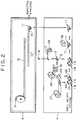
- a photographic film cassette 10 has a cassette shell 11 consisting of upper and lower shell halves 11a and 11b which are attached by ultrasonic welding.
- the upper and lower shell halves 11a and 11b have integrally formed respective port portions 12a and 12b which are mated together to form a film passage mouth 14 of the cassette shell 11, through which a photographic film 13 is let in and out of the cassette shell 11.
- a spool 15 having a core 16 and a pair of flanges 18.
- the core 16 is formed with a slit 16a having therein a pair of claws 16b.
- a trailing end 17a of a leader sheet 17 is secured to the core 16 through engagement between the claws 16b and holes 17b formed in the trailing end 17a.
- a trailing end 13a of the photographic film 13 is attached to a free end 17c of the leader sheet 17.
- the leader sheet 17 is formed of e.g., polysthylene terephthalate and its length is predetermined such that the free end 17c of the leader sheet 17 slightly protrudes, e.g., about 15mm, to the outside of the film passage mouth 14 when the shell halves 11a and 11b are jointed together after the spool 15 is accommodated therein.
- the flanges 18 are formed on both end portions of the core 16 and serve to prevent the photographic film 13 from loosening with its lateral edges being rubbed against the inner surfaces of the flanges 18 when the photographic film 13 is wound on the core 16.
- flexible plastic disks 19 are rotatably fitted on the core 16 at axially outside portions relative to the flanges 18.
- the disks 19 are formed integrally with circumferential ridges 19a.
- Lateral end surfaces of the upper and lower shell halves 11a and 11b are provided with semicircular cutouts 20a and 20b which form circular openings 20 for exposing end surfaces 16d of the core 16 to the outside when the upper and lower shell halves are joined together.
- Annular ridges 22a and 22b are formed on the lateral inside end surfaces of the upper and lower shell halves 11a and 11b so as to project inwardly to position the disks 19 such that they will not move in the axial direction of the spool 15. But, the ridges 22a and 22b are not formed in the vicinity of the port portions 12a and 12b.
- a separation claw 24 is formed on an innermost part of the port portion 12b of the lower shell half 11b to peel a leading end of the photographic film 13 off from the roll of photographic film 13 and to lead it toward the film passage mouth 14 as the spool 15 is rotated together with the photographic film 13.
- the inside surfaces of the port portions 12a and 12b have light-trapping pieces 25 attached thereto.
- a lighted room as indicated by Block A the cassette shell halves 11a and 11b are first placed on an assembly line. Then, the light-trapping pieces 25 are cut from a long sheet of light-trapping material 27 wound in a roll, and attached to the port portions 12a and 12b of the cassette shell halves 11a and 11b. In the meantime, the leader sheet 17 is cut at the predetermined length from a continuous roll of leader sheet material 28, inserted in the slit 16a, and secured to the spool 15 via the claws 16b formed within the slit 16a.
- the disks 19 are formed from a long sheet of disk material 29 wound in a roll, and freely mounted on the both end portions of the core 16. Then, after the spool 15 is put in between the shell halves 11a and 11b with the free end 17c of the leader sheet 17 being slightly projected from the film passage mouth 14, the shell halves 11a and 11b are mated to each other and securely attached by ultrasonic welding using an ultrasonic welding horn 30.
- the cassette shell 11 with the leader sheet 17 projected from the film passage mouth 14 are transferred to a darkroom as indicated by Block B.
- the photographic film 13 is cut at a predetermined length from a long roll of photographic film 31.
- the trailing end 13c of the photographic film 13 is attached to the free end 17c of the leader sheet 17 projected from the film passage mouth 14 by e.g., a double-coated tape or an adhesive.
- the entire length of the photographic film 13 is wound in the cassette shell 11 by rotation of the spool 15 resulting in completion of the photographic film cassette 10.
- the photographic film cassette 10 is again transferred to the lighted room, and subjected to inspection and packaging operations.
- the photographic film cassettes 10 are shipped to various places.
- the leader sheet 17 may be formed integrally with the spool 15.
- Figs. 3 and 4 show a photographic film cassette 40 according to a second embodiment of the present invention, wherein a spool 41 has a guide sheet 42 integrally formed therewith.
- the guide sheet 42 serves to guide a trailing end 13a of a photographic film 13 into a slit 41a formed in the spool 41 and to secure it to the spool 41 by means of claws 41b formed within the slit 41a.
- the width of the guide sheet 42 is approximately equal to that of the photographic film 13.
- a border portion 42a of the guide sheet 42 on the spool 41 is formed thinner than the other portion of the guide sheet 42 so that the guide sheet 42 is separated from the spool 41 when pulled with a strong force after the photographic film 13 has been secured to the spool 41.
- the spool 41 is accommodated in a cassette shell 43 in a state with the free end of the guide sheet 41a projected from a film passage mouth 44 to the outside, when upper and lower shell halves 43a and 43b made of resin material are joined securely by ultrasonic welding to form the cassette shell 43 in the lighted room. Then, the cassette shell 43 is transferred to the darkroom, where the trailing end 13a of the photographic film 13 is inserted through the film passage mouth 44, guided into the slit 41a along the guide sheet 42 arrested by the claws 41b. Thereafter, the guide sheet 42 is separated from the spool 41 and discarded. The photographic film 13 is then wound within the cassette shell 43 by rotation of the spool 41, resulting in completion of the photographic film cassette 40.
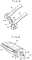
- Fig. 5 shows a spool 51 having a pair of guide strips 52 and 53 formed integrally therewith on opposite lateral sides of a slit 51a of the spool 51.
- This embodiment is an improvement of the spool 41 having the guide sheet 42 shown in Fig. 3, and designed so as to save the spool material.
- the guide strips 52 and 53 can be easy to tear off the spool 51 along thin wall portions 52a and 53a.
- the spool 51 is accommodated in a cassette shell (not shown) with the free ends of the guide strips 52 and 53 projected from a film passage mouth at the time of assembly the same as in the second embodiment.
- An end of a photographic film is inserted in the film passage mouth, guided into the slit 51a along the guide strips 52 and 53, and secured to the spool 51 by means of a claw 51b formed in the slit 51a. Thereafter, when the guide strips 52 and 53 are pulled, they are cut from the spool 51 along the thin wall portions 52a and 53a.
- Fig. 6 shows another embodiment of a photographic film cassette 60, wherein upper and lower shell halves 61a and 61b constituting a cassette shell 61 is prevented from the displacement during the ultrasonic welding.
- the upper shell half 61a is provided with projections 62 and 63 while the lower shell half 61b is provided with cutouts 64 and 65 at corresponding portions to the projections 62 and 63.
- the projections 62 and 63 are provided at their inner portions with claws while the cutouts 64 and 65 are provided at corresponding portions to the claws with recesses. Accordingly, the upper and lower shell halves 61a and 61b can be fixedly mated together by fitting the projections 62 and 63 in the respective cutouts 64 and 65.
- the guide sheet or the guide strips are separated from the spool in the above-described embodiment, but these guide member may be wound in the cassette shell together with the photographic film. In this case, there is no need to provide the thin wall portions.
Landscapes
- Physics & Mathematics (AREA)
- General Physics & Mathematics (AREA)
- Storage Of Web-Like Or Filamentary Materials (AREA)
- Details Of Cameras Including Film Mechanisms (AREA)
- Structure And Mechanism Of Cameras (AREA)
- Replacement Of Web Rolls (AREA)
- Lining Or Joining Of Plastics Or The Like (AREA)
- Photographic Processing Devices Using Wet Methods (AREA)
Priority Applications (1)
| Application Number | Priority Date | Filing Date | Title |
|---|---|---|---|
| EP97103291A EP0783131A3 (de) | 1992-07-16 | 1993-07-15 | Verfahren zum Zusammensetzen einer fotografischen Filmkassette |
Applications Claiming Priority (2)
| Application Number | Priority Date | Filing Date | Title |
|---|---|---|---|
| JP4189731A JP2967960B2 (ja) | 1992-07-16 | 1992-07-16 | 写真フイルムパトローネの組立方法 |
| JP189731/92 | 1992-07-16 |
Related Child Applications (1)
| Application Number | Title | Priority Date | Filing Date |
|---|---|---|---|
| EP97103291A Division EP0783131A3 (de) | 1992-07-16 | 1993-07-15 | Verfahren zum Zusammensetzen einer fotografischen Filmkassette |
Publications (3)
| Publication Number | Publication Date |
|---|---|
| EP0579228A2 true EP0579228A2 (de) | 1994-01-19 |
| EP0579228A3 EP0579228A3 (de) | 1994-01-26 |
| EP0579228B1 EP0579228B1 (de) | 1998-05-13 |
Family
ID=16246248
Family Applications (2)
| Application Number | Title | Priority Date | Filing Date |
|---|---|---|---|
| EP97103291A Withdrawn EP0783131A3 (de) | 1992-07-16 | 1993-07-15 | Verfahren zum Zusammensetzen einer fotografischen Filmkassette |
| EP93111378A Expired - Lifetime EP0579228B1 (de) | 1992-07-16 | 1993-07-15 | Photographische Filmkassette und Verfahren zur deren Montage |
Family Applications Before (1)
| Application Number | Title | Priority Date | Filing Date |
|---|---|---|---|
| EP97103291A Withdrawn EP0783131A3 (de) | 1992-07-16 | 1993-07-15 | Verfahren zum Zusammensetzen einer fotografischen Filmkassette |
Country Status (4)
| Country | Link |
|---|---|
| US (1) | US5462240A (de) |
| EP (2) | EP0783131A3 (de) |
| JP (1) | JP2967960B2 (de) |
| DE (1) | DE69318482T2 (de) |
Cited By (2)
| Publication number | Priority date | Publication date | Assignee | Title |
|---|---|---|---|---|
| EP0683423A1 (de) | 1994-05-17 | 1995-11-22 | Fuji Photo Film Co., Ltd. | Verfahren und Vorrichtung zur Zusammensetzung einer photographischen Filmkassette |
| EP0685758A1 (de) * | 1994-05-24 | 1995-12-06 | Fuji Photo Film Co., Ltd. | Verfahren und Vorrichtung zum Zusammenbau von Filmkassetten |
Families Citing this family (5)
| Publication number | Priority date | Publication date | Assignee | Title |
|---|---|---|---|---|
| JP3614974B2 (ja) * | 1996-04-24 | 2005-01-26 | 富士写真フイルム株式会社 | 写真フイルムの巻込み方法及び装置 |
| EP0828186B1 (de) * | 1996-09-04 | 2003-11-26 | Fuji Photo Film Co., Ltd. | Verfahren und Vorrichtung zur Rollfilmherstellung |
| US6317951B1 (en) | 1997-10-02 | 2001-11-20 | Fuji Photo Film Co., Ltd. | Method of and apparatus for processing photographic photosensitive film |
| US6213745B1 (en) | 1999-05-03 | 2001-04-10 | Dynisco | High-pressure, self-lubricating journal bearings |
| US6179594B1 (en) | 1999-05-03 | 2001-01-30 | Dynisco, Inc. | Air-cooled shaft seal |
Family Cites Families (15)
| Publication number | Priority date | Publication date | Assignee | Title |
|---|---|---|---|---|
| US2616634A (en) * | 1949-04-01 | 1952-11-04 | Melkon Onnig Diran | Film magazine |
| US2662696A (en) * | 1951-03-29 | 1953-12-15 | Graflex Inc | Film cartridge for photographic cameras |
| US2719679A (en) * | 1952-09-23 | 1955-10-04 | Graflex Inc | Means for engaging photographic film to connect the film to the spool or core of a cassette |
| US3003712A (en) * | 1959-03-03 | 1961-10-10 | Graflex Inc | Take-up spool for photographic cameras |
| US3640480A (en) * | 1970-03-09 | 1972-02-08 | Matix Corp | Scroll stripping method and apparatus |
| JPS5277723A (en) * | 1975-12-24 | 1977-06-30 | Fuji Photo Film Co Ltd | Film wind up process and cassette |
| US4166588A (en) * | 1978-09-11 | 1979-09-04 | Kreonite Inc. | Self-threading take-up magazine for a photographic printer |
| EP0135372A3 (de) * | 1983-09-16 | 1986-01-02 | R.P. Scherer Corporation | Gelatinekapsel und Verfahren und Vorrichtung zum Ultraschallschweissen der Kapseln |
| US4955555A (en) * | 1983-10-31 | 1990-09-11 | Eastman Kodak Company | Leader-retracting film magazine and method for enclosing film |
| EP0230057B1 (de) * | 1986-01-20 | 1990-05-16 | Agfa-Gevaert N.V. | Lichtdicht verpackte Rolle aus lichtempfindlichem Material |
| US4834306A (en) * | 1988-03-25 | 1989-05-30 | Eastman Kodak Company | Film cassette |
| EP0436767A3 (en) * | 1990-01-12 | 1992-08-26 | Fuji Photo Film Co., Ltd. | Film cassette |
| FR2657861B1 (fr) * | 1990-02-05 | 1992-06-12 | Kodak Pathe | Emballage distributeur pour materiau en bande. |
| EP0442501B1 (de) * | 1990-02-15 | 1997-06-18 | Fuji Photo Film Co., Ltd. | Photographische Filmkassette |
| US5215273A (en) * | 1991-11-19 | 1993-06-01 | Eastman Kodak Company | Film unwinding apparatus |
-
1992
- 1992-07-16 JP JP4189731A patent/JP2967960B2/ja not_active Expired - Fee Related
-
1993
- 1993-07-15 EP EP97103291A patent/EP0783131A3/de not_active Withdrawn
- 1993-07-15 EP EP93111378A patent/EP0579228B1/de not_active Expired - Lifetime
- 1993-07-15 DE DE69318482T patent/DE69318482T2/de not_active Expired - Fee Related
- 1993-07-15 US US08/091,627 patent/US5462240A/en not_active Expired - Lifetime
Cited By (5)
| Publication number | Priority date | Publication date | Assignee | Title |
|---|---|---|---|---|
| EP0683423A1 (de) | 1994-05-17 | 1995-11-22 | Fuji Photo Film Co., Ltd. | Verfahren und Vorrichtung zur Zusammensetzung einer photographischen Filmkassette |
| US5709022A (en) * | 1994-05-17 | 1998-01-20 | Fuji Photo Film Co., Ltd. | Method and apparatus for assembling photographic film cassette |
| EP0685758A1 (de) * | 1994-05-24 | 1995-12-06 | Fuji Photo Film Co., Ltd. | Verfahren und Vorrichtung zum Zusammenbau von Filmkassetten |
| US5647113A (en) * | 1994-05-24 | 1997-07-15 | Fuji Photo Film Co., Ltd. | Method for assembling photo film cassette |
| US5815911A (en) * | 1994-05-24 | 1998-10-06 | Fuji Photo Film Co., Ltd. | Apparatus for assembling photo film cassette |
Also Published As
| Publication number | Publication date |
|---|---|
| JP2967960B2 (ja) | 1999-10-25 |
| EP0783131A2 (de) | 1997-07-09 |
| US5462240A (en) | 1995-10-31 |
| EP0783131A3 (de) | 1997-07-16 |
| JPH0635128A (ja) | 1994-02-10 |
| DE69318482D1 (de) | 1998-06-18 |
| EP0579228B1 (de) | 1998-05-13 |
| DE69318482T2 (de) | 1998-09-17 |
| EP0579228A3 (de) | 1994-01-26 |
Similar Documents
| Publication | Publication Date | Title |
|---|---|---|
| US4834306A (en) | Film cassette | |
| US4894673A (en) | Film cassette | |
| EP0579228A2 (de) | Photographische Filmkassette und Verfahren zur deren Montage | |
| JP3036715B2 (ja) | 写真フイルムの巻込み方法及び装置並びに写真フイルムの引出し分離方法及び装置 | |
| US5031853A (en) | Film-thrusting cassette | |
| US5031855A (en) | Film-thrusting cassette | |
| US6491246B1 (en) | Pinch spools one-time use cameras apparatus and methods | |
| US4809923A (en) | Light-tight film reel | |
| US5105604A (en) | Method for light-tightly enclosing a photosensitive web roll | |
| EP0726488A1 (de) | Verfahren und Vorrichtung zur Aufbewahrung und Ausgabe von aufgewickeltem photographischem Bahnmaterial | |
| US5181672A (en) | Photograhic film cassette | |
| US6622365B2 (en) | Pinch quill, apparatus, and film winding method | |
| JP2980138B2 (ja) | 写真フイルムカートリッジ | |
| JP2000258873A (ja) | 合成樹脂製フィルムパトローネ | |
| JPH0453648Y2 (de) | ||
| JPH0611800A (ja) | ロールフィルム収納カートリッジの組立方法及び装置 | |
| JP3002058B2 (ja) | ロールフィルム収納カートリッジの組立方法 | |
| EP0525615B1 (de) | Verpackung mit einer biegsamen, lichtdichten Hülle für Rollen von photoempfindlichem Gewebe und deren Herstellungsverfahren | |
| JPH0631465Y2 (ja) | ロールフィルム | |
| US5159373A (en) | Method for light-shielding a photosensitive web end | |
| EP0554921A2 (de) | Filmkassette | |
| JPH11212216A (ja) | ロール状感光材料用遮光フランジ及びロール状感光材料 | |
| JPH06214346A (ja) | フィルムパトローネ | |
| JPH06148806A (ja) | 写真用ロールフィルムのカートリッジ | |
| JPH07181631A (ja) | 写真フィルム用パトローネ及びそれに収納される写真フィルム |
Legal Events
| Date | Code | Title | Description |
|---|---|---|---|
| PUAI | Public reference made under article 153(3) epc to a published international application that has entered the european phase |
Free format text: ORIGINAL CODE: 0009012 |
|
| PUAL | Search report despatched |
Free format text: ORIGINAL CODE: 0009013 |
|
| AK | Designated contracting states |
Kind code of ref document: A2 Designated state(s): DE FR NL |
|
| AK | Designated contracting states |
Kind code of ref document: A3 Designated state(s): DE FR NL |
|
| RHK1 | Main classification (correction) |
Ipc: G03B 17/30 |
|
| 17P | Request for examination filed |
Effective date: 19940613 |
|
| 17Q | First examination report despatched |
Effective date: 19950913 |
|
| GRAG | Despatch of communication of intention to grant |
Free format text: ORIGINAL CODE: EPIDOS AGRA |
|
| GRAG | Despatch of communication of intention to grant |
Free format text: ORIGINAL CODE: EPIDOS AGRA |
|
| GRAH | Despatch of communication of intention to grant a patent |
Free format text: ORIGINAL CODE: EPIDOS IGRA |
|
| GRAH | Despatch of communication of intention to grant a patent |
Free format text: ORIGINAL CODE: EPIDOS IGRA |
|
| GRAA | (expected) grant |
Free format text: ORIGINAL CODE: 0009210 |
|
| AK | Designated contracting states |
Kind code of ref document: B1 Designated state(s): DE FR NL |
|
| PG25 | Lapsed in a contracting state [announced via postgrant information from national office to epo] |
Ref country code: NL Free format text: LAPSE BECAUSE OF FAILURE TO SUBMIT A TRANSLATION OF THE DESCRIPTION OR TO PAY THE FEE WITHIN THE PRESCRIBED TIME-LIMIT Effective date: 19980513 |
|
| XX | Miscellaneous (additional remarks) |
Free format text: TEILANMELDUNG 97103291.7 EINGEREICHT AM 27/02/97. |
|
| REF | Corresponds to: |
Ref document number: 69318482 Country of ref document: DE Date of ref document: 19980618 |
|
| ET | Fr: translation filed | ||
| NLV1 | Nl: lapsed or annulled due to failure to fulfill the requirements of art. 29p and 29m of the patents act | ||
| PLBE | No opposition filed within time limit |
Free format text: ORIGINAL CODE: 0009261 |
|
| STAA | Information on the status of an ep patent application or granted ep patent |
Free format text: STATUS: NO OPPOSITION FILED WITHIN TIME LIMIT |
|
| 26N | No opposition filed | ||
| REG | Reference to a national code |
Ref country code: FR Ref legal event code: TP Ref country code: FR Ref legal event code: CD |
|
| PGFP | Annual fee paid to national office [announced via postgrant information from national office to epo] |
Ref country code: DE Payment date: 20080724 Year of fee payment: 16 |
|
| PGFP | Annual fee paid to national office [announced via postgrant information from national office to epo] |
Ref country code: FR Payment date: 20080718 Year of fee payment: 16 |
|
| REG | Reference to a national code |
Ref country code: FR Ref legal event code: ST Effective date: 20100331 |
|
| PG25 | Lapsed in a contracting state [announced via postgrant information from national office to epo] |
Ref country code: FR Free format text: LAPSE BECAUSE OF NON-PAYMENT OF DUE FEES Effective date: 20090731 |
|
| PG25 | Lapsed in a contracting state [announced via postgrant information from national office to epo] |
Ref country code: DE Free format text: LAPSE BECAUSE OF NON-PAYMENT OF DUE FEES Effective date: 20100202 |