EP0579334A2 - Machine d'emballage ajustable - Google Patents
Machine d'emballage ajustable Download PDFInfo
- Publication number
- EP0579334A2 EP0579334A2 EP93202117A EP93202117A EP0579334A2 EP 0579334 A2 EP0579334 A2 EP 0579334A2 EP 93202117 A EP93202117 A EP 93202117A EP 93202117 A EP93202117 A EP 93202117A EP 0579334 A2 EP0579334 A2 EP 0579334A2
- Authority
- EP
- European Patent Office
- Prior art keywords
- side frames
- packaging machine
- bed
- devices
- holders
- Prior art date
- Legal status (The legal status is an assumption and is not a legal conclusion. Google has not performed a legal analysis and makes no representation as to the accuracy of the status listed.)
- Granted
Links
Images


Classifications
-
- B—PERFORMING OPERATIONS; TRANSPORTING
- B65—CONVEYING; PACKING; STORING; HANDLING THIN OR FILAMENTARY MATERIAL
- B65B—MACHINES, APPARATUS OR DEVICES FOR, OR METHODS OF, PACKAGING ARTICLES OR MATERIALS; UNPACKING
- B65B59/00—Arrangements to enable machines to handle articles of different sizes, to produce packages of different sizes, to vary the contents of packages, to handle different types of packaging material, or to give access for cleaning or maintenance purposes
-
- B—PERFORMING OPERATIONS; TRANSPORTING
- B65—CONVEYING; PACKING; STORING; HANDLING THIN OR FILAMENTARY MATERIAL
- B65B—MACHINES, APPARATUS OR DEVICES FOR, OR METHODS OF, PACKAGING ARTICLES OR MATERIALS; UNPACKING
- B65B3/00—Packaging plastic material, semiliquids, liquids or mixed solids and liquids, in individual containers or receptacles, e.g. bags, sacks, boxes, cartons, cans, or jars
-
- B—PERFORMING OPERATIONS; TRANSPORTING
- B65—CONVEYING; PACKING; STORING; HANDLING THIN OR FILAMENTARY MATERIAL
- B65B—MACHINES, APPARATUS OR DEVICES FOR, OR METHODS OF, PACKAGING ARTICLES OR MATERIALS; UNPACKING
- B65B43/00—Forming, feeding, opening or setting-up containers or receptacles in association with packaging
- B65B43/42—Feeding or positioning bags, boxes, or cartons in the distended, opened, or set-up state; Feeding preformed rigid containers, e.g. tins, capsules, glass tubes, glasses, to the packaging position; Locating containers or receptacles at the filling position; Supporting containers or receptacles during the filling operation
- B65B43/54—Means for supporting containers or receptacles during the filling operation
-
- B—PERFORMING OPERATIONS; TRANSPORTING
- B65—CONVEYING; PACKING; STORING; HANDLING THIN OR FILAMENTARY MATERIAL
- B65B—MACHINES, APPARATUS OR DEVICES FOR, OR METHODS OF, PACKAGING ARTICLES OR MATERIALS; UNPACKING
- B65B59/00—Arrangements to enable machines to handle articles of different sizes, to produce packages of different sizes, to vary the contents of packages, to handle different types of packaging material, or to give access for cleaning or maintenance purposes
- B65B59/005—Adjustable conveying means
-
- B—PERFORMING OPERATIONS; TRANSPORTING
- B65—CONVEYING; PACKING; STORING; HANDLING THIN OR FILAMENTARY MATERIAL
- B65B—MACHINES, APPARATUS OR DEVICES FOR, OR METHODS OF, PACKAGING ARTICLES OR MATERIALS; UNPACKING
- B65B65/00—Details peculiar to packaging machines and not otherwise provided for; Arrangements of such details
Definitions
- the present invention relates to packaging machines, for example, to a packaging machine for filling dessert into cuplike containers and thereafter closing the opening of each container with a strip of closure material.
- Packaging machines of the type mentioned comprise a container conveyor mounted on a bed, and a group of devices mounted on the bed and successively arranged along the path of transport of the conveyor, the group of devices including at least a container feeder, filling device, sealing device and container discharging device.
- the bed comprises a pair of opposite side frames extending in parallel to the direction of transport of the conveyor, and a plurality of holders connected between the frames and corresponding in number to the number of devices. The holders respectively have the devices attached thereto and are secured to the side frames by welding.
- the main object of the present invention is to provide a packaging machine which readily permits alteration of the layout of component devices.
- the present invention provides a packaging machine which comprises a container conveyor mounted on a bed, and a group of devices mounted on the bed and successively arranged along the path of transport of the conveyor, the group of devices including at least a filling device and a sealing device, the bed comprising a pair of side frames extending in parallel to the direction of transport of the conveyor, and a plurality of holders connected between the frames and corresponding in number to the number of the devices, the holders respectively having the devices attached thereto.
- the packaging machine is characterized in that at least one of the holders is movable longitudinally of the side frames and has fixing means for releasably fixing the movable holder at a desired position along the length of the side frames.
- At least one of the holders is free to move longitudinally of the side frames, and the machine has fixing means for releasably fixing the movable holder at an optional position along the length of the side frames, so that the position of the device can be altered by unfastening the holder from the side frames, moving the holder and fixing the holder to the side frames again.
- the position of the device can be altered readily.
- front refers to the side (right-hand side of FIG. 1) toward which containers advance as transported by the conveyor, and the term “rear” to the opposite side.
- rear refers to the opposite side.
- right and left are used for the machine as it is seen from the front rearward, and refer to the right and the left of FIG. 3.
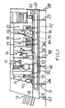
- FIG. 1 shows a packaging machine, which comprises a bed 11, a container conveyor 12 mounted on the bed, and a container feeder 13, extraneous matter removing device 14, filling device 15, rewinder 16, sealing device 17, trimmer 18, winder 19, skirt folding device 21 and discharge device 22 which are arranged along the path of transport of the conveyor 12.
- the bed 11 comprises right and left side frames 24, right and left side covers 25 covering the respective side frames 24 from outside, three pairs of right and left support legs 26, 27, 28 fixed to the side frames 24 respectively at three locations, i.e., near their rear ends, near their front ends and at the front ends, and seven kinds of holders 31 to 37 fixed to the side frames 24 and respectively having attached thereto the removing device 14, filling device 15, rewinder 16, sealing device 17, trimmer 18, winder 19 and folding device 21 included in the group of devices and other than the container feeder 13 and discharge device 22.
- the container conveyor 12 which is a slat conveyor, comprises a pair of opposite front drive sprockets 41 and a pair of opposite rear driven sprockets 42 which are mounted on the respective side frames 24 by suitable means not shown in detail, a pair of opposite chains reeved around the sprockets 41, 42 at the respective sides, and a multiplicity of slats 45 connected between the chains 43 (see FIG. 3).
- the container feeder 13 and discharge device 22 are fixed to the side frames 24 by suitable means not shown in detail.
- the container feeder 13 is provided with a pair of right and left auxiliary support legs 47.
- the holders 32 for the filling device and the holders 33 for the winder are provided with a pair of right and left auxiliary support legs 48 and like auxiliary support legs 49, respectively.
- Each of the side frames 24 comprises upper and lower guide rails 51, 52 made of a pipe of circular cross section and extending in parallel to each other longitudinally of the machine.
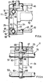
- FIG. 2 shows structures for fixing typical one of the three pairs of support legs 26, 27, 28, i.e., the support leg 28 at the front frame ends, to the side frames 24.
- the front ends of the upper and lower rails 51, 52 of the side frame 24 are held between the support leg 28 and upper and lower two vertical flat platelike clamp members 53 provided on the left side face of the leg.
- the support leg 28 is formed at upper portions thereof with U-shaped leftwardly open cutouts 54, in which the upper and lower rails 51, 52 are fitted, respectively, with a left side portion of each rail slightly projecting from the cutout 54.
- each of the clamp members 53 is formed at the midportion of its length with an arcuate cutout 55 having fitted therein the projecting portion of the rail 51 (52).
- Two fastening bolts 56 extend through the clamp member 53 at its upper and lower end portions and are screweed into the support leg 28.
- Two horizontal connecting bars 57 are connected between the opposite support legs 28 at lower portions thereof.
- FIGS. 2 and 3 show a structure for fixing the sealing.device holder 34, which is typical of the seven kinds of holders 31 to 37, to the side frames 24.
- the holder 34 comprises a pair of right and left vertical members 61 extending across the upper and lower guide rails 51, 52 of the respective side frames 24, and a transverse member 62 provided between these vertical members 61.
- the upper and lower rails 51, 52 of the left side frame 24 are held between the vertical member 61 and upper and lower two clamp members 63 provided on the left side face of the member 61 and each in the form of a vertical flat plate.
- the vertical member 61 is formed with two semicircular leftwardly open cutouts 64 having fitted therein approximately right halves of the upper and lower rails 51, 52.
- each clamp member 63 is formed at the midportion of its length with a semicircular rightwardly open cutout 65 having fitted therein approximately the left half of the rail 51 (52).
- Two fastening bolts 66 extend through the clamp member 63 at its upper and lower end portions and are screwed into the vertical member 61.
- Right and left posts 68 are provided upright on the upper ends of the respective vertical members 61 by means of connectors 67.
- the upper ends of the posts 68 are interconnected by a top plate 69, from which the sealing device 17 is suspended.
- the transverse member 62 is provided with backup members 71 which are vertical plates arranged in parallel for receiving the pressure of sealing operation.
- the holder 34 is free to move with ths sealing device 17 along the rails 51, 52 when the bolts 66 are loosened. When the bolts 66 are tightened up, the holder 34 is fastened to the rails 51, 52 in place.
- FIG. 6 shows a modified packaging machine comprising the machine shown in FIG. 1 and further having incorporated therein optional devices, which lengthened the machine.
- the modified packaging machine comprises a bed 81 and the devices of FIG. 1 mounted thereon, i.e., the container feeder 13, extraneous matter removing device 14, filling device 15, rewinder 16, sealing device 17, trimmer 18, winder 19, skirt folding device 21 and discharge device. Additionally, the machine has a secondary filling device 82 and a secondary rewinder 83 which are arranged between the filling device 15 and the rewinder 16, and a secondary sealing device 84 disposed between the sealing device 17 and the trimmer 18. These three devices 82 to 84 are also fixed to side frames 88 of the bed 81 by holders 85 to 87, respectively.
Landscapes
- Engineering & Computer Science (AREA)
- Mechanical Engineering (AREA)
- Auxiliary Devices For And Details Of Packaging Control (AREA)
- Closing Of Containers (AREA)
Priority Applications (1)
| Application Number | Priority Date | Filing Date | Title |
|---|---|---|---|
| EP94202070A EP0628480B1 (fr) | 1992-07-17 | 1993-07-16 | Machine d'emballage ajustable |
Applications Claiming Priority (2)
| Application Number | Priority Date | Filing Date | Title |
|---|---|---|---|
| JP50249/92U | 1992-07-17 | ||
| JP1992050249U JP2602693Y2 (ja) | 1992-07-17 | 1992-07-17 | 包装機械 |
Related Child Applications (1)
| Application Number | Title | Priority Date | Filing Date |
|---|---|---|---|
| EP94202070.2 Division-Into | 1993-07-16 |
Publications (3)
| Publication Number | Publication Date |
|---|---|
| EP0579334A2 true EP0579334A2 (fr) | 1994-01-19 |
| EP0579334A3 EP0579334A3 (fr) | 1994-03-16 |
| EP0579334B1 EP0579334B1 (fr) | 1996-10-16 |
Family
ID=12853714
Family Applications (2)
| Application Number | Title | Priority Date | Filing Date |
|---|---|---|---|
| EP94202070A Expired - Lifetime EP0628480B1 (fr) | 1992-07-17 | 1993-07-16 | Machine d'emballage ajustable |
| EP93202117A Expired - Lifetime EP0579334B1 (fr) | 1992-07-17 | 1993-07-16 | Machine d'emballage ajustable |
Family Applications Before (1)
| Application Number | Title | Priority Date | Filing Date |
|---|---|---|---|
| EP94202070A Expired - Lifetime EP0628480B1 (fr) | 1992-07-17 | 1993-07-16 | Machine d'emballage ajustable |
Country Status (5)
| Country | Link |
|---|---|
| EP (2) | EP0628480B1 (fr) |
| JP (1) | JP2602693Y2 (fr) |
| KR (1) | KR100276133B1 (fr) |
| DE (2) | DE69311703T2 (fr) |
| DK (2) | DK0628480T3 (fr) |
Cited By (3)
| Publication number | Priority date | Publication date | Assignee | Title |
|---|---|---|---|---|
| EP0816235A1 (fr) * | 1996-07-03 | 1998-01-07 | Optima-Maschinenfabrik Dr. Bühler GmbH & Co. | Dispositif d'emballage d'articles |
| DE20305759U1 (de) * | 2003-04-08 | 2004-08-19 | Finnah Engineering Und Packaging Gmbh | Maschine zum Abfüllen von flüssigen Nahrungs- und Genußmitteln in Becher |
| EP4059851A3 (fr) * | 2021-03-18 | 2023-06-07 | Osgood Industries, LLC | Cadre de support réglable pour unité de traitement |
Families Citing this family (5)
| Publication number | Priority date | Publication date | Assignee | Title |
|---|---|---|---|---|
| JP4172830B2 (ja) * | 1997-01-08 | 2008-10-29 | 四国化工機株式会社 | 高速液体充填機械 |
| JP4486328B2 (ja) | 2003-07-09 | 2010-06-23 | 四国化工機株式会社 | チェーンレス容器搬送装置 |
| JP2008230621A (ja) * | 2007-03-16 | 2008-10-02 | Tokyo Autom Mach Works Ltd | 縦形製袋充填包装機 |
| JP5399435B2 (ja) * | 2011-03-29 | 2014-01-29 | 株式会社フジキカイ | 横形製袋充填機の物品供給コンベヤ |
| JP6765785B2 (ja) * | 2015-03-19 | 2020-10-07 | 株式会社イシダ | 製袋包装機 |
Family Cites Families (7)
| Publication number | Priority date | Publication date | Assignee | Title |
|---|---|---|---|---|
| FR1330730A (fr) * | 1961-07-28 | 1963-06-28 | Perfectionnements apportés aux procédés et dispositifs de soudage pour machines àformer des récipients clos | |
| FR1414231A (fr) * | 1964-11-06 | 1965-10-15 | Hassia Verpackungsmaschinen G | Dispositif pour emboutir, remplir, sceller et séparer les récipients en matière plastique |
| BE791329A (fr) * | 1972-09-18 | 1973-03-01 | Illinois Tool Works | Assemblage |
| DE2458287A1 (de) * | 1974-12-10 | 1976-06-16 | Munz Geb Lobenberg Brigitte | Allzweck-rahmengestell in baukastenform |
| FR2496226B1 (fr) * | 1980-12-12 | 1985-12-20 | Alsthom Cgee | Support pour profile |
| JPS5974005A (ja) * | 1982-10-06 | 1984-04-26 | エービー テトラパック | 複数ユニツトからなる機械における分離・移動装置 |
| DE9112617U1 (de) * | 1991-10-10 | 1992-07-09 | Natec Reich, Summer GmbH & Co KG, 8996 Opfenbach | Gestellteil als Teil eines Maschinengestells für die Nahrungsmittelindustrie |
-
1992
- 1992-07-17 JP JP1992050249U patent/JP2602693Y2/ja not_active Expired - Fee Related
-
1993
- 1993-07-16 DK DK94202070.2T patent/DK0628480T3/da active
- 1993-07-16 DE DE69311703T patent/DE69311703T2/de not_active Expired - Fee Related
- 1993-07-16 DK DK93202117.3T patent/DK0579334T3/da active
- 1993-07-16 DE DE69305439T patent/DE69305439T2/de not_active Expired - Fee Related
- 1993-07-16 EP EP94202070A patent/EP0628480B1/fr not_active Expired - Lifetime
- 1993-07-16 EP EP93202117A patent/EP0579334B1/fr not_active Expired - Lifetime
- 1993-07-16 KR KR1019930013557A patent/KR100276133B1/ko not_active Expired - Fee Related
Cited By (3)
| Publication number | Priority date | Publication date | Assignee | Title |
|---|---|---|---|---|
| EP0816235A1 (fr) * | 1996-07-03 | 1998-01-07 | Optima-Maschinenfabrik Dr. Bühler GmbH & Co. | Dispositif d'emballage d'articles |
| DE20305759U1 (de) * | 2003-04-08 | 2004-08-19 | Finnah Engineering Und Packaging Gmbh | Maschine zum Abfüllen von flüssigen Nahrungs- und Genußmitteln in Becher |
| EP4059851A3 (fr) * | 2021-03-18 | 2023-06-07 | Osgood Industries, LLC | Cadre de support réglable pour unité de traitement |
Also Published As
| Publication number | Publication date |
|---|---|
| DK0579334T3 (da) | 1996-11-18 |
| DE69305439D1 (de) | 1996-11-21 |
| EP0628480B1 (fr) | 1997-06-18 |
| JPH0610108U (ja) | 1994-02-08 |
| DE69311703T2 (de) | 1997-12-18 |
| DE69305439T2 (de) | 1997-03-06 |
| DK0628480T3 (da) | 1997-08-04 |
| EP0628480A1 (fr) | 1994-12-14 |
| JP2602693Y2 (ja) | 2000-01-24 |
| KR100276133B1 (ko) | 2000-12-15 |
| EP0579334B1 (fr) | 1996-10-16 |
| DE69311703D1 (de) | 1997-07-24 |
| EP0579334A3 (fr) | 1994-03-16 |
| KR940005468A (ko) | 1994-03-21 |
Similar Documents
| Publication | Publication Date | Title |
|---|---|---|
| DE2502943C2 (de) | Verteilungsvorrichtung zur Förderung von Schüttgut von einer Vorratsquelle zu mehreren Verbraucherstellen | |
| US5078250A (en) | Universal safety guard assembly for a conveyor | |
| EP0579334B1 (fr) | Machine d'emballage ajustable | |
| EP0831028B1 (fr) | Convoyeur pour une machine de remplissage et/ou de bouchage | |
| DE2456840C3 (de) | Behältnis zur Lagerung, Führung und UmschnUruflg eines nicht stabilen Stapels aus waagrecht liegenden, blattartigem Material | |
| US20170225812A1 (en) | Stacking apparatus and method for binding operations | |
| EP0135892A2 (fr) | Dispositif de scellement latéral pour machine d'emballage verticale | |
| US5116033A (en) | Apparatus for collecting, asssembling and inserting printery products | |
| US5398804A (en) | Curved conveyor belt with supporting frame devoid of belt band rollers | |
| DE4103479C2 (de) | Vorrichtung zum Verstellen des Aufnahmevolumens eines Gutträgers | |
| EP0215341B1 (fr) | Dispositif pour munir des piles de cahiers de plaques de marquage et pour le transport desdites piles en dispositifs d'empilage dans des imprimeries | |
| JPH09512778A (ja) | コンベヤ | |
| DE3810484A1 (de) | Briefumschlag-paketieranlage | |
| DE3736925A1 (de) | Vorrichtung zum einfuehren des fuehrungsendes eines verpackungsbandes in eine foerdereinrichtung | |
| EP0679592B1 (fr) | Bande transporteuse à plaques | |
| EP0194711B1 (fr) | Dispositif pour fermer les volets latéraux supérieurs d'une boîte ayant des volets pliants | |
| DE3503812C2 (de) | Vorrichtung zum Aufstecken von Säcken auf einen Füllstutzen | |
| EP0376926B1 (fr) | Dispositif pour remplir des éléments d'espacement de vitrage isolant | |
| US3389804A (en) | Supporting track and advancing pawls for article display and storage apparatus | |
| DE4323127A1 (de) | Kurvenbandförderer mit gurtbandrollenfreiem Traggerüst | |
| CN209870887U (zh) | 一种气雾罐输送装置 | |
| EP1295819A2 (fr) | Dispositif pour le transport suspendu de récipients à goulot, en particulier de bouteilles PET | |
| CN220701480U (zh) | 预制菜装箱系统 | |
| DE3221243A1 (de) | Vorrichtung zum stapeln flacher gegenstaende | |
| DE3822241C1 (en) | Apparatus for slipping a shrinkable wrapping over a package |
Legal Events
| Date | Code | Title | Description |
|---|---|---|---|
| PUAI | Public reference made under article 153(3) epc to a published international application that has entered the european phase |
Free format text: ORIGINAL CODE: 0009012 |
|
| AK | Designated contracting states |
Kind code of ref document: A2 Designated state(s): CH DE DK FR GB LI NL SE |
|
| PUAL | Search report despatched |
Free format text: ORIGINAL CODE: 0009013 |
|
| AK | Designated contracting states |
Kind code of ref document: A3 Designated state(s): CH DE DK FR GB LI NL SE |
|
| 17P | Request for examination filed |
Effective date: 19940705 |
|
| K1C3 | Correction of patent application (complete document) published |
Effective date: 19940119 |
|
| GRAG | Despatch of communication of intention to grant |
Free format text: ORIGINAL CODE: EPIDOS AGRA |
|
| 17Q | First examination report despatched |
Effective date: 19960219 |
|
| GRAH | Despatch of communication of intention to grant a patent |
Free format text: ORIGINAL CODE: EPIDOS IGRA |
|
| GRAH | Despatch of communication of intention to grant a patent |
Free format text: ORIGINAL CODE: EPIDOS IGRA |
|
| GRAA | (expected) grant |
Free format text: ORIGINAL CODE: 0009210 |
|
| AK | Designated contracting states |
Kind code of ref document: B1 Designated state(s): CH DE DK FR GB LI NL SE |
|
| XX | Miscellaneous (additional remarks) |
Free format text: TEILANMELDUNG 94202070.2 EINGEREICHT AM 16/07/93. |
|
| DX | Miscellaneous (deleted) | ||
| REG | Reference to a national code |
Ref country code: CH Ref legal event code: NV Representative=s name: PATENTANWALTSBUERO JEAN HUNZIKER |
|
| ET | Fr: translation filed | ||
| REG | Reference to a national code |
Ref country code: DK Ref legal event code: T3 |
|
| REF | Corresponds to: |
Ref document number: 69305439 Country of ref document: DE Date of ref document: 19961121 |
|
| PLBE | No opposition filed within time limit |
Free format text: ORIGINAL CODE: 0009261 |
|
| 26N | No opposition filed | ||
| REG | Reference to a national code |
Ref country code: GB Ref legal event code: IF02 |
|
| PGFP | Annual fee paid to national office [announced via postgrant information from national office to epo] |
Ref country code: CH Payment date: 20020708 Year of fee payment: 10 |
|
| PGFP | Annual fee paid to national office [announced via postgrant information from national office to epo] |
Ref country code: GB Payment date: 20020709 Year of fee payment: 10 |
|
| PGFP | Annual fee paid to national office [announced via postgrant information from national office to epo] |
Ref country code: SE Payment date: 20020717 Year of fee payment: 10 |
|
| PGFP | Annual fee paid to national office [announced via postgrant information from national office to epo] |
Ref country code: DK Payment date: 20020719 Year of fee payment: 10 |
|
| PG25 | Lapsed in a contracting state [announced via postgrant information from national office to epo] |
Ref country code: GB Free format text: LAPSE BECAUSE OF NON-PAYMENT OF DUE FEES Effective date: 20030716 |
|
| PG25 | Lapsed in a contracting state [announced via postgrant information from national office to epo] |
Ref country code: SE Free format text: LAPSE BECAUSE OF NON-PAYMENT OF DUE FEES Effective date: 20030717 |
|
| PGFP | Annual fee paid to national office [announced via postgrant information from national office to epo] |
Ref country code: NL Payment date: 20030725 Year of fee payment: 11 |
|
| PGFP | Annual fee paid to national office [announced via postgrant information from national office to epo] |
Ref country code: FR Payment date: 20030728 Year of fee payment: 11 |
|
| PG25 | Lapsed in a contracting state [announced via postgrant information from national office to epo] |
Ref country code: LI Free format text: LAPSE BECAUSE OF NON-PAYMENT OF DUE FEES Effective date: 20030731 Ref country code: DK Free format text: LAPSE BECAUSE OF NON-PAYMENT OF DUE FEES Effective date: 20030731 Ref country code: CH Free format text: LAPSE BECAUSE OF NON-PAYMENT OF DUE FEES Effective date: 20030731 |
|
| EUG | Se: european patent has lapsed | ||
| GBPC | Gb: european patent ceased through non-payment of renewal fee |
Effective date: 20030716 |
|
| REG | Reference to a national code |
Ref country code: CH Ref legal event code: PL Ref country code: DK Ref legal event code: EBP |
|
| PGFP | Annual fee paid to national office [announced via postgrant information from national office to epo] |
Ref country code: DE Payment date: 20040623 Year of fee payment: 12 |
|
| PG25 | Lapsed in a contracting state [announced via postgrant information from national office to epo] |
Ref country code: NL Free format text: LAPSE BECAUSE OF NON-PAYMENT OF DUE FEES Effective date: 20050201 |
|
| PG25 | Lapsed in a contracting state [announced via postgrant information from national office to epo] |
Ref country code: FR Free format text: LAPSE BECAUSE OF NON-PAYMENT OF DUE FEES Effective date: 20050331 |
|
| NLV4 | Nl: lapsed or anulled due to non-payment of the annual fee |
Effective date: 20050201 |
|
| REG | Reference to a national code |
Ref country code: FR Ref legal event code: ST |
|
| PG25 | Lapsed in a contracting state [announced via postgrant information from national office to epo] |
Ref country code: DE Free format text: LAPSE BECAUSE OF NON-PAYMENT OF DUE FEES Effective date: 20060201 |