EP3559755B1 - Flexible monolithisches bauteil für uhren - Google Patents
Flexible monolithisches bauteil für uhren Download PDFInfo
- Publication number
- EP3559755B1 EP3559755B1 EP17825498.3A EP17825498A EP3559755B1 EP 3559755 B1 EP3559755 B1 EP 3559755B1 EP 17825498 A EP17825498 A EP 17825498A EP 3559755 B1 EP3559755 B1 EP 3559755B1
- Authority
- EP
- European Patent Office
- Prior art keywords
- monolithic component
- rigid
- component according
- flexible structure
- timepiece
- Prior art date
- Legal status (The legal status is an assumption and is not a legal conclusion. Google has not performed a legal analysis and makes no representation as to the accuracy of the status listed.)
- Active
Links
Images



Classifications
-
- G—PHYSICS
- G04—HOROLOGY
- G04B—MECHANICALLY-DRIVEN CLOCKS OR WATCHES; MECHANICAL PARTS OF CLOCKS OR WATCHES IN GENERAL; TIME PIECES USING THE POSITION OF THE SUN, MOON OR STARS
- G04B19/00—Indicating the time by visual means
- G04B19/24—Clocks or watches with date or week-day indicators, i.e. calendar clocks or watches; Clockwork calendars
- G04B19/243—Clocks or watches with date or week-day indicators, i.e. calendar clocks or watches; Clockwork calendars characterised by the shape of the date indicator
- G04B19/247—Clocks or watches with date or week-day indicators, i.e. calendar clocks or watches; Clockwork calendars characterised by the shape of the date indicator disc-shaped
- G04B19/253—Driving or releasing mechanisms
-
- G—PHYSICS
- G04—HOROLOGY
- G04B—MECHANICALLY-DRIVEN CLOCKS OR WATCHES; MECHANICAL PARTS OF CLOCKS OR WATCHES IN GENERAL; TIME PIECES USING THE POSITION OF THE SUN, MOON OR STARS
- G04B13/00—Gearwork
-
- G—PHYSICS
- G04—HOROLOGY
- G04B—MECHANICALLY-DRIVEN CLOCKS OR WATCHES; MECHANICAL PARTS OF CLOCKS OR WATCHES IN GENERAL; TIME PIECES USING THE POSITION OF THE SUN, MOON OR STARS
- G04B13/00—Gearwork
- G04B13/02—Wheels; Pinions; Spindles; Pivots
-
- G—PHYSICS
- G04—HOROLOGY
- G04B—MECHANICALLY-DRIVEN CLOCKS OR WATCHES; MECHANICAL PARTS OF CLOCKS OR WATCHES IN GENERAL; TIME PIECES USING THE POSITION OF THE SUN, MOON OR STARS
- G04B5/00—Automatic winding up
- G04B5/02—Automatic winding up by self-winding caused by the movement of the watch
- G04B5/04—Automatic winding up by self-winding caused by the movement of the watch by oscillating weights the movement of which is limited
- G04B5/08—Automatic winding up by self-winding caused by the movement of the watch by oscillating weights the movement of which is limited acting in both directions
-
- G—PHYSICS
- G04—HOROLOGY
- G04B—MECHANICALLY-DRIVEN CLOCKS OR WATCHES; MECHANICAL PARTS OF CLOCKS OR WATCHES IN GENERAL; TIME PIECES USING THE POSITION OF THE SUN, MOON OR STARS
- G04B5/00—Automatic winding up
- G04B5/02—Automatic winding up by self-winding caused by the movement of the watch
- G04B5/18—Supports, suspensions or guide arrangements, for oscillating weights
- G04B5/185—Suspension of the moving weight by elastic means
Definitions
- the present invention relates to a monolithic component intended for a timepiece, in particular a mechanical timepiece, designed to transmit the movement of an actuator of the timepiece to a driven part of the timepiece. watchmaking.
- patent application WO 2012/010408 discloses resilient pivot oscillating mechanisms and power transmission mobiles comprising such oscillating mechanisms, which aim to replace a balance, respectively a conventional escapement, so as to produce a regulating member using single-piece components.
- the patent application EP 1 306 733 discloses a control member of which at least two parts are made in a single piece, but which also comprises other articulated parts, which are not all located in the same plane.
- Japanese patent JP 4,917,909 presents a jumper consisting of a base fixed to the bridge and a rigid end serving as an indexing tip, two elastic arms serving as a link between the base and the indexing tip, the jumper making it possible to secure the position of a toothed ring.
- the patent application EP 2 977 830 presents an escape mechanism provided with a rocker mounted on a flexible guide, but moving only in rotation.
- the present invention aims to reduce the number of components constituting a complete mechanism or a functional sub-assembly, with a view to reduce the problems associated with friction and the clearances between these components constituting a conventional horological mechanism, control the positioning, and thus guarantee the reliability of the mechanism. More specifically, the invention relates to functional monolithic components of the defined input type, allowing the transmission of energy by means of a drive along trajectories of various directions. Another object of the invention is to provide monolithic components forming a constant force transmission member which allows better reproducibility and better safety of the actuation of the driven part. In addition, the aim of the invention is to produce such monolithic components by means of manufacturing techniques known to watchmaking construction.
- the present invention therefore proposes monolithic components formed from a plurality of rigid zones and of flexible zones.
- the terms “rigid” and “flexible” are to be understood here within the framework of the watchmaking field, that is to say that a flexible zone undergoes sufficient bending for the desired transmission of movement under the effect of mechanical force. that the actuator is capable of producing, while in this situation a rigid zone does not deform significantly.
- the actuator can be a part independent of the monolithic component, coming into contact with said first drive member to generate said movements.
- the actuator can also be integral with the monolithic component.
- the components of said displacement with two degrees of freedom are chosen from among translations, rotations and their combinations.
- the first resiliently flexible structure may comprise two flexible blades each extending between said frame and said first drive member.
- the points of contact of the two flexible blades with the first drive member can be arranged in different zones of said first drive member.
- One of the two said flexible blades may comprise a portion bent substantially at right angles.
- a rigid intermediate part can be arranged between two flexible portions of the flexible structure.
- the first resiliently flexible structure can also comprise one or more flexible necks arranged between two rigid elements of said monolithic component.
- the monolithic component preferably comprises a second functional member and a second elastically flexible structure connecting said frame to said second functional member, said second elastically flexible structure being configured so as to place said second functional organ in contact with a driven part.
- said second functional member is a holding member, configured to temporarily secure a part driven by said first drive member in its position.
- said driven part is a toothed disc
- the actuator is a control wheel equipped with a drive finger
- said first drive member is a rocker
- said second functional member is a saltire
- the monolithic component constitutes an automatic winding mechanism, incorporating an oscillating mass as an actuator, the driven part being an automatic winding wheel, and said first drive member comprising two fingers which both play, alternately, the role of coach finger.
- the aforementioned components are preferably made of hardenable steels, also called maraging steels, for example Durnico steel. Such materials, in sheets or thin sheets, can be machined by wire cutting, by stamping, or even by femtoprint to produce components extending in a single plane.
- the figure 1 shows an actuator kinematic chain - monolithic component - driven part schematically illustrating and by way of example the inventive concept.
- This chain comprises an actuating finger 1, a monolithic component according to the invention, and a driven part 5 which may for example consist of a toothed wheel or of a ring / toothed disc.
- the monolithic component comprises several parts, namely a first rigid drive member 3, a second rigid functional member 4, namely in the embodiment illustrated by way of example on figure 1 a holding member 4, a rigid frame 6, a first elastically flexible structure - comprising in the embodiment illustrated by way of example on figure 1 two flexible blades 2, 2 '- which connects the first rigid drive member 3 to the frame 6, and a second elastically flexible structure - formed in the embodiment illustrated by way of example in figure 1 by a flexible blade 2 "- which connects the second functional member 4, in the example illustrated the holding member 4, to the frame 6.
- the frame 6 is the part of the monolithic component according to the present invention making it possible to fix it to the frame.
- the monolithic component necessarily comprises a first rigid drive member 3 fixed to the rigid frame 6 by said first elastically flexible structure 2, 2 ', the presence of a second rigid functional member 4 fixed to the rigid frame 6 by a second elastically flexible structure 2 "is only optional.
- the actuating finger 1 fixed to a control wheel rotatably mounted in said timepiece, slides, during the progressive rotation of said control wheel, on a suitable portion 31 of the first rigid drive member 3, generating a movement of the latter controlled by the first elastically flexible structure, that is to say in the example illustrated in figure 1 by the two blades 2, 2 ', and limited by the contact of said first drive member 3 with the driven wheel 5.
- the end of the rigid drive member 3 in the form of a hook constitutes a drive means 34 able to engage with the teeth of the driven wheel 5 in order to drive it.
- the drive means 34 performs a movement having a component parallel to the circumference of said driven wheel 5 and a component perpendicular to said circumference.
- the assembly of the first drive member 3 performs an alternating two-dimensional oscillation movement.
- This movement is possible thanks to the elastic deformation of the blades 2, 2 ', of the first elastically flexible structure, and causes, when the drive means 34 engages in the teeth of the driven wheel 5, the rotation of the wheel. driven 5 in the direction of the arrow shown in figure 1 .
- the displacement of the driven part 5 is a rotation but could also be a pivoting, a translation, or any other displacement depending on the concrete application for which the monolithic component according to the present invention is used.
- the elastic contact of this retaining member 4 with the driven wheel 5 secures, outside of the phases of driving the wheel driven 5 by the first member rigid drive 3, this driven wheel 5 against any inadvertent rotation.
- the function of the second functional member 4 may, in general, consist of a function other than maintaining a given part of a corresponding timepiece, this part not necessarily being the part 5 driven by the corresponding timepiece.
- a kinematic chain as shown by way of example in figure 1 can be produced, using a monolithic component according to the present invention, using only a maximum of three separate physical parts, namely the actuator, the monolithic component, and the driven part.
- the principle illustrated through the example of the figure 1 can be realized in the form of a multitude of variations, in particular by modifying the arrangement of the first elastically flexible structure and / or of the second elastically flexible structure as well as, alternatively or additionally, the function and / or the arrangement of the first rigid drive member and / or of the second functional member.
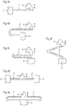
- FIGS. 2a to 2h are schematic views illustrating the inventive concept of a guidance with several degrees of freedom by means of a connection by an elastically flexible structure 2, 2 ', in particular by several flexible blades, between a rigid frame 6 and a rigid functional member 3
- Eight embodiments of a monolithic component with flexible blades, in these cases with a single functional member, are represented therein, in order to show by way of example at least part of the multitude of potentially achievable variants, given that it is not possible to describe here all the possible variants.
- the frames 6 are shown with crosses, the functional members 3 are shown hatched, and the blades 2, 2 'of the resiliently flexible structures do not have hatching since they are quite thin, rigid intermediate parts 7 can be part of the elastically flexible structures - as indicated schematically in the figures 2c and 2h - are grayed out.
- the rigid intermediate parts 7 are areas of the monolithic component which are markedly thicker than the areas constituting the flexible blades 2, 2 '.
- the actuator respectively the actuating finger 1, which impacts the rigid functional member 3, preferably at the end of the functional member 3 opposite its end in the form of an engaging hook.
- an elastically flexible structure - comprising at least two flexible blades 2, 2 'as well as optionally at least one rigid intermediate part 7 - between the rigid frame 6 and the functional member 3 allows a predefined displacement with at least two degrees of freedom of the latter.
- the presence of at least one bend at approximately 90 ° in at least one of the flexible blades 2, 2 'of the elastically flexible structure allows, respectively, considerably increases, the freedom of movement of the functional organ 3 in one of the directions of its movement.
- the flexible blade 2 of the embodiments of a monolithic component according to the figures 2a, 2b , 2d, 2e, 2f, and 2g forms an elbow at about 90 °.
- the functional member 3 of the corresponding monolithic component can not only move in a substantially horizontal direction in this plane, but, thanks to this bend, also a movement in one direction substantially vertical in this plane.
- the bend at approximately 90 ° is preferably formed on the flexible blade 2 located towards the end of the functional member 3 in the form of a hook which engages in the driven part 5 and therefore acts as a driving finger.
- an elastically flexible structure forms an elbow at approximately 90 ° by means of at least one rigid intermediate part 7, as illustrated in FIGS. figures 2c and 2h .
- the flexible blade 2 comprises several flexible parts oriented perpendicular to each other and separated by a rigid intermediate part 7.
- the flexible blade 2, which is formed by several parts separated by a rigid intermediate part 7 in order to form an elbow at approximately 90 ° is preferably located towards the end of the functional member 3 in the form of a hook engaging in the driven part 5 and therefore having the role of a trainer finger.
- the figures 2c and 2h show that a flexible blade 2 'or also 2 can be fixed either directly to the rigid frame 6 or to the rigid intermediate part 7.
- the figures 2a to 2h also indicate, schematically using the arrows and by way of example, types of combinations of movement achievable by a monolithic component according to the present invention which provides guidance with at least two degrees of freedom of a functional member rigid by means of a connection by an elastically flexible structure, in particular by at least two flexible blades, between a rigid frame and this rigid functional member.
- the figures 2a, 2b , 2d, 2e, 2f, and 2g show a monolithic component whose first resiliently flexible structure comprises flexible blades 2, 2 'configured so as to ensure a displacement of at least two degrees of freedom of said first drive member 3, that is to say of the functional organ, the two degrees of freedom of the predefined movement of the functional organ 3 consisting of a rotation combined with a movement according to a distant center of elasticity (CÉÉ / also called "remote center of compliance (RCC)).
- CÉÉ distant center of elasticity
- the figures 2c and 2h show a monolithic component whose first resiliently flexible structure comprises flexible blades 2, 2 'configured so as to ensure a displacement of at least two degrees of freedom of the functional member 3, the two degrees of freedom of the predefined movement of the functional member 3 consisting of two combined translations, respectively of a combined translation with a movement according to a distant center of elasticity.
- first resiliently flexible structure comprises flexible blades 2, 2 'configured so as to ensure a displacement of at least two degrees of freedom of the functional member 3, the two degrees of freedom of the predefined movement of the functional member 3 consisting of two combined translations, respectively of a combined translation with a movement according to a distant center of elasticity.
- the figure 3 shows a monolithic component according to the present invention capable of being integrated into an instantaneous date mechanism of a corresponding timepiece.
- This component is intended to fit into a kinematic chain such as that shown in figure 1 .
- the reference numbers and graphics are the same as above, as well as the structure and operation of the device, respectively of the kinematic chain, as explained in the context of the figure 1 .
- said driven part is a date disc / ring, preferably having teeth on its inner periphery
- the actuator is a control wheel equipped with an actuating finger, also not shown in figure 3
- said first drive member 3 is formed by a drive lever, one end of which is capable of being actuated by said actuating finger and of which the other end equipped with a drive finger is capable of s' engage in the teeth of said date ring in order to drive it in steps
- said second functional member 4 is a jumper capable of securing said date ring in its position, outside the phases of driving this ring by the first member drive 3.
- this monolithic component serves as a drive and securing member of a date disc / ring.
- a functional organ in in particular said second functional member serving as jumper 4
- this holding element can become, during a period of time during operation of the mechanism, a drive element.
- the general arrangement, respectively the operation, of an instantaneous date mechanism are known to those skilled in the art and will therefore not be described here, the description being limited to the monolithic component according to the present invention.
- the monolithic component shown on figure 3 allows itself to replace more than ten parts, including pins and axes, usually used in a date mechanism construction according to the state of the art.
- the figure 6 shows a basic kinematic diagram of a monolithic component according to the invention in which the flexible blades 2, 2 'have been replaced by rigid elements articulated at their ends by pivot connections. This component extends in a work plane which is that of the figures 1 to 3 .
- the kinematic diagram of the figure 6 corresponds to the embodiments presented on the figures 1 to 3 except for the figure 2c and will be used in the following to explain more generally the function of the parts of a monolithic component according to the present invention.
- the first elastically flexible structure of a monolithic component comprises a first flexible blade 2 extending between the frame 6 and the drive member 3 and defining a first point of embedding 32 at the level of the drive member 3.
- This first fitting point 32 is movable with reference to the frame 6 along a linear path with a degree of freedom situated in the work plane.
- This trajectory can be an arc of a circle as in the figures 2d, 2e, 2f, 2g, 2h or 6 .
- the shape of the flexible blade 2 may have two parts extending in substantially opposite directions so that the displacement of the point embedding 32 is substantially rectilinear as is the case in the embodiments presented in figures 1 , 2a , 2b and 3 .
- the flexibility of the blade 2 means that the rigid drive member 3 is movable in rotation with reference to the frame 6 about an axis perpendicular to the work plane.
- the first elastically flexible structure of a monolithic component according to the present invention comprises a second flexible blade 2 'defining a second embedding point 33 at the level of the drive member 3.
- the second flexible blade 2 ' comprises (in addition) two parts extending in substantially perpendicular directions and interconnected by an elbow 35 shown in figure 6 symbolically by a pivot link.
- the two parts of the second flexible blade 2 ' can be physically separated by a rigid intermediate part 7 as in the configuration of the figure 2h .
- the second embedding point 33 is movable with reference to the frame 6 along a plane path with two degrees of freedom located in the work plane.
- the invention is not limited to monolithic components of which the second flexible blade 2 ′ comprises two distinct parts separated by an elbow or a rigid intermediate part.
- the second flexible blade 2 ' can have any kind of geometry adapted so that the second blade 2' can flex, causing a displacement of the second embedding point 33 in the work plan.
- the first 32 and second 33 points of embedding of the first 2 and second 2 flexible blades in the first drive member 3 are arranged in different zones of said first drive member 3.
- the distance between the points d 'embedding 32 and 33 represents at least a quarter of the length of the flexible blade 2. More specifically, moving away the embedding points 32, 33 greatly increases the moment quadratic of the first flexible structure along an axis of the work plane, in other words, to improve the guidance of the first drive member 3 in the work plane.
- moving the mounting points 32, 33 away makes it possible to reduce the quadratic moment and therefore the section of each of the flexible blades.
- the drive means 34 is also remote from the embedding point 32 so that its movement takes place according to two degrees of freedom in the work plane. It is advantageous to provide stops cooperating with the first drive member 3 and / or the flexible arms 2, 2 ′ to limit the deformation of the elastically flexible structure to its elastic range.
- the stops can for example be integrated into the rigid frame 6.
- the deformations of the flexible blades 2, 2 ' are limited and define a work zone 36 in which the drive means 34 is mobile, illustrated schematically on figure 6 by a hatched area.
- the flexible blades 2, 2 'exert an elastic return force which tends to return the drive means 34 to a rest position substantially in the center of the work zone 36.
- the actuator 1 acting on the adapted portion 31 of the first drive member 3 causes a movement of the drive means 34 which describes a working path 37 shown, by way of example, on the figure 1 .
- the work path 37 delimits a non-zero surface by forming a loop, that is to say that the return path to the rest position is not superimposed on the outward path. This loop can be obtained e in response to movement of the actuator 1 only.
- the actuator 1 can, for example, be an eccentric guiding a circular movement of the adapted portion 31 which will cause a work path 37 in the form of a loop.
- the movement of the drive member 3 is also generated by the driven part 5. This is the case in the example of figure 1 where the driven part 5 deflects the outward path of the drive means 34, the drive means 34 sliding on a tooth of the driven part 5 until it passes it to drive it on the return path.
- the movement of the drive member 3 can also be generated by an additional guide element intended to come into contact with the first drive member 3 moving under the action. of the actuator.
- the additional guide element can come from the frame 6 or be fixed to a bridge, to the plate or to another element of the timepiece.
- the actuation of a mechanism by an actuating force capable of varying has several drawbacks. This is for example the case when a user actuates a mechanism directly using a control member.
- the mechanism must be sized to withstand the most powerful actuations, which may for example result from an impact on a push-button.
- additional safety devices may need to be provided to secure the position of moving parts.
- the actuating force also varies when the actuator of the mechanism is moved by the energy source of the timepiece, the motor torque of which varies according to the winding. In this second case, it will be necessary to ensure the operation of the mechanism over an extended range of actuation force which, in the case of positioning by a jumper, can complicate the design of the mechanism.
- the present invention makes it possible to remedy these drawbacks by proposing a monolithic component producing a constant force actuation device.
- the monolithic component according to the invention makes it possible to accumulate energy coming from the actuator in elastic form and to restore it with a constant force to the driven part, independently of the actuating force of the actuator. Indeed, the drive of the driven part 5 is caused only by the return to the rest position of the drive means 34 under the action of the flexible blades 2, 2 '.
- the indirect transmission of the actuating force using the monolithic component of the invention thus makes it possible to make the mechanisms to be actuated more reliable and secure and to simplify their design.
- FIGS. 4a to 4f are schematic views illustrating with the same reference numbers and graphics as above in the context of the figure 1 six embodiments of a second functional member 4, in particular of a holding member as used in the application illustrated in figure 3 .
- This retaining member 4 is connected to a part of a rigid frame 6 by means of a second elastically flexible structure, consisting of one or two blades 2.
- a second elastically flexible structure consisting of one or two blades 2.
- the flexible blade (s) 2 "of a second elastically flexible structure can be configured as a straight blade, a full or partial U-shaped, a full or partial V-shaped, or even a straight double blade, respectively a double U or V-shaped blade, or even a combinations of these configurations.
- the figure 5 shows a monolithic component constituting with the driven part an automatic winding mechanism capable of being integrated into a timepiece. Part numbers and graphics are the same as above, especially in the context of the figure 1 .
- this monolithic component is permanently attached to an actuator formed by an oscillating mass 1 ', so that the kinematic chain actuator - monolithic component - driven part is in this case achievable using only two separate physical parts, namely the monolithic component according to the present invention and the driven part.
- the oscillating weight 1 ' is connected to the frame 6 of the monolithic component by two flexible necks 2 "', that is to say by two short pieces having a central narrowing allowing them to bend and thus acting as a flexible blade.
- the frame 6 may include a bridge with a larger surface serving as an attachment point for said two flexible necks 2 '"connecting the two intermediate parts 7 to the frame 6 as well as a peripheral part of substantially circular shape surrounding said oscillating weight 1' and the rigid intermediate parts 7.
- Two other flexible necks 2 "' attached preferably close to the corresponding ends of the two intermediate parts 7 which are integral with the oscillating mass 1', connect said two rigid intermediate parts 7 of substantially straight shape to a third rigid intermediate part 7 of shape substantially square with a rounded angle.
- This third rigid intermediate part 7 is centrally located between said two rigid intermediate parts 7 of substantially straight shape arranged parallel to one another.
- the third rigid intermediate part 7 surrounds a winding wheel automatic 5, which in this application of the monolithic component forms the driven part, and carries two flexible blades 2, 2 'arranged tangentially with respect to said winding wheel 5.
- Each of the two flexible blades 2, 2' is terminated by a first member rigid drive 3, respectively by a second drive member 4, in particular by d hook-shaped drive pins 3, 4.
- each of the first and second rigid drive members 3, 4 is connected to the frame 6 by means of a corresponding first elastically flexible structure comprising two rigid intermediate parts 7 of substantially straight shape, a third rigid intermediate part 7 , four flexible necks 2 '"secured to the rigid intermediate parts 7 of straight shape and, in part, to the third rigid intermediate part 7, and a flexible blade 2, 2'.
- first elastically flexible structures which are distinguished only by the flexible blade 2 or 2 ', form a bend at about 90 °, analogously to what has been explained above with respect to figures 2c and 2h .
- the rigid functional members in the form of the drive fingers 3, 4 are able to engage in the teeth of the winding wheel 5 and both play, alternately, the role of drive finger when the mass 1 'oscillates from left to right and vice versa and that the two flexible blades 2, 2 'perform a corresponding movement.
- the monolithic component therefore drives using the drive fingers 3, 4, at each oscillation of sufficient amplitude of the oscillating weight 1 ', respectively at each sufficient movement of one of the two flexible blades 2, 2', the automatic winding wheel 5 in rotation, so that it turns one or more notch (s) in the direction of the arrow, depending on the amplitude of oscillation of the oscillating weight 1 '.
- the monolithic component can also be used by having only the first member. rigid drive 3.
- the general operation of an automatic winding mechanism is moreover known to those skilled in the art and will therefore not be described in more detail here.
- the monolithic component described above makes it possible to replace a set of at least a dozen parts constituting an automatic winding mechanism, for example of the Pellaton type, of the prior art.
- the drive means 34 constitutes a unidirectional drive device for the output mobile.
- the flexible structure is positioned between the frame 6 and the drive member so as to make the drive means 34 movable with reference to the frame according to two degrees of freedom in a work plane which is that of the figure in the example of figure 5 .
- the flexible structure may include rigid intermediate parts 7 as in the examples of figures 2c and 2h .
- At least one mass 1 ' is integral with the flexible structure.
- the mass can be added or be part of the monolithic component as in the example shown in figure 5 .
- the mass 1 ' is movable with reference to the frame according to at least one degree of freedom in the work plane.
- the elastic members of the flexible structure bring the mass towards a rest position so that together they constitute an oscillator.
- the accelerations supplied to the timepiece cause the displacement of the mass which in its movement causes the drive means 34 and consequently the driven member 5.
- the mass can be mobile in rotation or according to several degrees of freedom in the work plane.
- the monolithic component can be made of hardenable steel, preferably Durnico steel.
- it can be machined by wire cutting, by stamping, or by femtoprint which consists of a modification of the physical properties and a machining of transparent material by means of a femtosecond laser, followed by a hetching, but in all the cases so as to extend into a single plane.
- Other manufacturing techniques for such a monolithic component can be envisaged, for example, Liga, 3D printing, and all manufacturing processes related to silicon.
- the height of such a monolithic component is preferably found in a range of 0.1 mm to 5 mm and the width of the flexible blades of its first elastically flexible structure is found to be preferably within a range of 5 ⁇ m to 1 mm, but these values may also be somewhat outside these ranges.
- this monolithic component can be produced in a multitude of embodiments arranged differently according to the needs of the specific watchmaking application, so that it can be used for a considerable number of watchmaking applications.
- this monolithic component allows several important advantages to be achieved.
Landscapes
- Physics & Mathematics (AREA)
- General Physics & Mathematics (AREA)
- Micromachines (AREA)
- Transmission Devices (AREA)
- Toys (AREA)
- Electric Clocks (AREA)
Claims (15)
- Monolithisches Bauteil, das für eine Uhr, insbesondere für eine mechanische Uhr, bestimmt ist und das geeignet ist, die Bewegung eines Wirkglieds (1, 1') der Uhr auf ein angetriebenes Teil (5) der Uhr zu übertragen, dadurch gekennzeichnet, dass das monolithische Bauteil umfasst- ein starres Gestell (6),- ein erstes starres Antriebsorgan (3), und- eine erste elastisch flexible Struktur (2, 2', 2''', 7), die das besagte Gestell (6) mit dem besagten ersten Antriebsorgan (3) verbindet,und dadurch, dass die besagte erste elastisch flexible Struktur (2, 2', 2''', 7) derart ausgestaltet ist, dass sie eine Verlagerung mit mindestens zwei Freiheitsgraden des besagten ersten Antriebsorgans (3) gewährleistet, wobei die besagte Verlagerung unter der Wirkung des Wirkglieds (1, 1') bewirkt wird.
- Monolithisches Bauteil nach Anspruch 1, dadurch gekennzeichnet, dass die Verlagerung unter der Wirkung eines Kontakts des ersten Antriebsorgans (3) mit dem angetriebenen Teil (5) bewirkt wird.
- Monolithisches Bauteil nach einem der vorhergehenden Ansprüche, dadurch gekennzeichnet, dass die Verlagerung unter der Wirkung eines Kontakts des ersten Antriebsorgans (3) mit einem zusätzlichen Führungselement bewirkt wird.
- Monolithisches Bauteil nach einem der vorhergehenden Ansprüche, dadurch gekennzeichnet, dass das besagte Wirkglied (1) ein unabhängiges Teil ist, das geeignet ist, mit dem besagten monolithischen Bauteil in Kontakt zu treten, um die besagte Verlagerung zu bewirken.
- Monolithisches Bauteil nach einem der Ansprüche 1 bis 3, dadurch gekennzeichnet, dass das besagte Wirkglied (1') fest mit dem besagten monolithischen Bauteil verbunden ist.
- Monolithisches Bauteil nach einem der vorhergehenden Ansprüche, dadurch gekennzeichnet, dass die Komponenten der besagten Verlagerung mit mindestens zwei Freiheitsgraden aus translatorischen Bewegungen, Drehungen, Bewegungen mit einem passiven Ausgleichselement (Remote Center of Compliance/RCC) und ihren Kombinationen ausgewählt sind.
- Monolithisches Bauteil nach einem der vorhergehenden Ansprüche, dadurch gekennzeichnet, dass die besagte erste elastisch flexible Struktur zwei flexible Blätter (2, 2') umfasst, die sich jeweils zwischen dem besagten Gestell (6) und dem besagten ersten Antriebsorgan (3) erstrecken.
- Monolithisches Bauteil nach dem vorhergehenden Anspruch, dadurch gekennzeichnet, dass die Kontaktpunkte der zwei flexiblen Blätter (2, 2') mit dem ersten Antriebsorgan (3) in verschiedenen Zonen des besagten ersten Antriebsorgans (3) angeordnet sind.
- Monolithisches Bauteil nach einem der vorhergehenden Ansprüche 7 bis 8, dadurch gekennzeichnet, dass eines von den zwei besagten flexiblen Blättern (2, 2') einen merklich im rechten Winkel gebogenen Abschnitt umfasst.
- Monolithisches Bauteil nach einem der vorhergehenden Ansprüche, dadurch gekennzeichnet, dass ein starres Zwischenteil (7) zwischen zwei flexiblen Abschnitten der besagten ersten elastisch flexiblen Struktur, insbesondere zwischen zwei Abschnitten der flexiblen Blätter (2, 2') dieser ersten elastisch flexiblen Struktur, angeordnet ist.
- Monolithisches Bauteil nach einem der vorhergehenden Ansprüche, dadurch gekennzeichnet, dass die besagte erste elastisch flexible Struktur einen oder mehrere flexible Hälse (2''') umfasst, der bzw. die zwischen zwei starren Elementen (6, 7) des besagten monolithischen Bauteils angeordnet ist bzw. sind.
- Monolithisches Bauteil nach einem der vorhergehenden Ansprüche, dadurch gekennzeichnet, dass es ein zweites Funktionsorgan (4) und eine zweite elastisch flexible Struktur (2") umfasst, die das besagte Gestell (6) mit dem besagten zweiten Funktionsorgan (4) verbindet, wobei die besagte zweite elastisch flexible Struktur (2") derart ausgestaltet ist, dass sie das besagte zweite Funktionsorgan (4) mit einem angetriebenen Teil in Kontakt bringt.
- Monolithisches Bauteil nach dem vorhergehenden Anspruch, dadurch gekennzeichnet, dass das besagte angetriebene Teil (5) eine Datumsscheibe oder ein Datumsring ist, dass das Wirkglied ein Steuerrad ist, das mit einem Betätigungsfinger (1) ausgerüstet ist, dass das besagte erste starre Antriebsorgan (3) eine Wippe ist, die mit dem starren Gestell (6) durch eine erste elastisch flexible Struktur verbunden ist, die flexible Blätter (2, 2') umfasst, und dass das besagte zweite Funktionsorgan (4) eine Hebelfeder ist, die durch eine zweite elastisch flexible Struktur (2") mit dem starren Gestell (6) verbunden ist, derart dass das besagte monolithische Bauteil als Antriebs- und Sicherungsorgan eines Datumsrads oder einer Datumsscheibe eines Datumsmechanismus der entsprechenden Uhr dient.
- Monolithisches Bauteil nach einem der vorhergehenden Ansprüche 1 bis 11, dadurch gekennzeichnet, dass das besagte angetriebene Teil (5) ein automatisches Aufziehrad ist, dass das Wirkglied eine Schwungmasse (1") ist, die fest mit dem monolithischen Bauteil verbunden ist, und dass das besagte erste starre Antriebsorgan (3) zwei Antriebsfinger (3, 4) umfasst, die jeweils mit dem starren Gestell (6) durch eine erste elastisch flexible Struktur verbunden sind, die flexible Blätter (2, 2', 2''') sowie starre Zwischenteile (7) umfasst, und die so angeordnet sind, um beide abwechselnd die Rolle als Antriebsfinger zu spielen, der geeignet ist, das automatische Aufziehrad anzutreiben, derart, dass das besagte monolithische Bauteil als Antriebsorgan eines Aufziehrades eines automatischen Aufziehmechanismus der entsprechenden Uhr dient.
- Uhr, insbesondere mechanische Uhr, dadurch gekennzeichnet, dass sie ein monolithisches Bauteil nach einem der vorhergehenden Ansprüche umfasst.
Applications Claiming Priority (2)
| Application Number | Priority Date | Filing Date | Title |
|---|---|---|---|
| CH01737/16A CH713288A1 (fr) | 2016-12-23 | 2016-12-23 | Composant monolithique flexible pour pièce d'horlogerie. |
| PCT/EP2017/083646 WO2018115014A2 (fr) | 2016-12-23 | 2017-12-19 | Composant monolithique flexible pour pièce d'horlogerie |
Publications (2)
| Publication Number | Publication Date |
|---|---|
| EP3559755A2 EP3559755A2 (de) | 2019-10-30 |
| EP3559755B1 true EP3559755B1 (de) | 2020-11-11 |
Family
ID=60935831
Family Applications (1)
| Application Number | Title | Priority Date | Filing Date |
|---|---|---|---|
| EP17825498.3A Active EP3559755B1 (de) | 2016-12-23 | 2017-12-19 | Flexible monolithisches bauteil für uhren |
Country Status (6)
| Country | Link |
|---|---|
| US (1) | US12055896B2 (de) |
| EP (1) | EP3559755B1 (de) |
| JP (1) | JP7105779B2 (de) |
| CN (1) | CN109952541B (de) |
| CH (1) | CH713288A1 (de) |
| WO (1) | WO2018115014A2 (de) |
Families Citing this family (17)
| Publication number | Priority date | Publication date | Assignee | Title |
|---|---|---|---|---|
| EP3644129B1 (de) * | 2018-10-24 | 2025-07-30 | Patek Philippe SA Genève | Flexibles steuerorgan |
| JP7240877B2 (ja) * | 2019-01-07 | 2023-03-16 | シチズン時計株式会社 | 時差修正機構及び時差修正機構付時計 |
| CH715864B1 (fr) * | 2019-02-19 | 2022-08-15 | Richemont Int Sa | Organe de blocage pour un mouvement horloger. |
| NL2023420B1 (en) * | 2019-07-02 | 2021-02-02 | Flexous Mech Ip B V | Watch or timepiece |
| NL2023823B1 (en) * | 2019-09-12 | 2021-05-17 | Flexous Mech Ip B V | Watch |
| EP3795855A1 (de) | 2019-09-20 | 2021-03-24 | Patek Philippe SA Genève | Herstellungsverfahren einer uhrfeder aus monokristallinem material, und nach diesem verfahren erzeugte uhrfeder |
| CH716983A1 (fr) | 2019-12-20 | 2021-06-30 | Mft Dhorlogerie Audemars Piguet Sa | Mécanisme horloger destiné à être entraîné suivant un nombre de pas variable. |
| EP3919988A1 (de) * | 2020-06-04 | 2021-12-08 | Montres Breguet S.A. | Gelenkmechanismus eines uhrwerks mit flexibler führung |
| CH718176A1 (fr) * | 2020-12-16 | 2022-06-30 | Mft Dhorlogerie Audemars Piguet Sa | Mécanisme de transmission pour mouvement horloger et mécanisme de remontage automatique le comportant. |
| JP2024514353A (ja) * | 2021-04-21 | 2024-04-01 | パテック フィリップ ソシエテ アノニム ジュネーブ | 時計機構又は時計を備えることを意図し且つ少なくとも1つの弾性要素及び少なくとも1つの第1及び第2時計コンポーネントを含む組立体 |
| EP4137892B1 (de) * | 2021-08-20 | 2025-04-02 | Montres Breguet S.A. | Blendenartige auslösevorrichtung, insbesondere für uhrwerke |
| EP4137893A1 (de) * | 2021-08-20 | 2023-02-22 | Montres Breguet S.A. | Blendenartige auslösevorrichtung, insbesondere für uhrwerke |
| EP4202567A1 (de) * | 2021-12-22 | 2023-06-28 | Montres Breguet S.A. | Anordnung von entgegengesetzten flexiblen führungen für ein uhrwerk, insbesondere für eine anzeigevorrichtung |
| EP4215999A1 (de) | 2022-01-24 | 2023-07-26 | Flexous Mechanisms IP B.V. | Energiegewinner für eine wearable- und/oder tragbare vorrichtung |
| JP2025519420A (ja) | 2022-06-23 | 2025-06-26 | エルブイエムエイチ・スイス・マニュファクチャーズ・ソシエテ・アノニム | 双安定性の時計制御機構 |
| JP2025519419A (ja) | 2022-06-23 | 2025-06-26 | エルブイエムエイチ・スイス・マニュファクチャーズ・ソシエテ・アノニム | 双安定性の時計制御機構 |
| EP4425275B1 (de) * | 2023-02-28 | 2025-12-17 | LVMH Swiss Manufactures SA | Uhrmechanismus |
Family Cites Families (56)
| Publication number | Priority date | Publication date | Assignee | Title |
|---|---|---|---|---|
| CH634668A4 (de) | 1968-04-29 | 1970-08-31 | ||
| JPS52139468A (en) * | 1976-05-17 | 1977-11-21 | Seiko Instr & Electronics Ltd | Calendar correcting mechanism for timepiece |
| FR2754577B1 (fr) | 1996-10-11 | 1998-12-11 | Suisse Electronique Microtech | Pivot flexible planaire a modules unitaires monolithiques |
| FR2759136B1 (fr) | 1997-02-06 | 1999-03-26 | Suisse Electronique Microtech | Dispositif de guidage en translation rectiligne d'un objet mobile par rapport a un objet fixe |
| WO1999064936A1 (fr) | 1998-06-08 | 1999-12-16 | Manufacture Des Montres Rolex S.A. | Procede pour transmettre des impulsions d'energie mecanique d'unesource motrice a un regulateur oscillant |
| CH692529A5 (fr) | 1998-07-23 | 2002-07-15 | Leschot Sa | Dispositif compteur de points destiné à équiper une montre. |
| CH695802A5 (fr) | 2001-10-23 | 2006-08-31 | Franck Muller Watchland Sa | Dispositif de commande pour pièce d'horlogerie. |
| JP4386022B2 (ja) * | 2004-11-10 | 2009-12-16 | セイコーエプソン株式会社 | 時計の表示装置、ムーブメント、および時計 |
| EP1736838B1 (de) | 2005-06-23 | 2008-03-19 | CSEM Centre Suisse d'Electronique et de Microtechnique S.A. - Recherche et Développement | Uhr |
| JP2008058012A (ja) * | 2006-08-29 | 2008-03-13 | Seiko Instruments Inc | 時計用ジャンパ付き歯車、時計のスリップ機構付き歯車構造体、時刻修正構造、及び時差修正付き時計 |
| JP4917909B2 (ja) | 2007-02-15 | 2012-04-18 | セイコーインスツル株式会社 | ジャンパ構造体並びにこれを備えたカレンダ機構及びカレンダ機構付き時計 |
| CH708113B1 (de) * | 2007-09-13 | 2014-12-15 | Stéphane Von Gunten | Anker für eine Uhrenhemmung. |
| EP2105806B1 (de) | 2008-03-27 | 2013-11-13 | Sowind S.A. | Hemmungsmechanismus |
| CH701421B1 (fr) | 2009-07-10 | 2014-11-28 | Manuf Et Fabrique De Montres Et Chronomètres Ulysse Nardin Le Locle Sa | Oscillateur mécanique. |
| EP2290476B1 (de) | 2009-08-18 | 2014-04-23 | CSEM Centre Suisse d'Electronique et de Microtechnique SA - Recherche et Développement | Isochronismuskorrektor für Uhrhemmungsmechanismus und mit einem solchen Korrektor ausgestatteter Hemmungsmechanismus |
| WO2011120180A1 (fr) | 2010-04-01 | 2011-10-06 | Rolex S.A. | Dispositif de blocage pour roue dentée |
| CH703464B1 (fr) | 2010-07-19 | 2013-11-29 | Nivarox Sa | Mécanisme oscillant à pivot élastique. |
| US9201398B2 (en) | 2010-07-19 | 2015-12-01 | Nivarox-Far S.A. | Oscillating mechanism with an elastic pivot and mobile element for transmitting energy |
| JP5729665B2 (ja) | 2010-09-14 | 2015-06-03 | セイコーインスツル株式会社 | 時計用デテント脱進機、および機械式時計 |
| JP5729666B2 (ja) | 2010-09-14 | 2015-06-03 | セイコーインスツル株式会社 | 時計用デテント脱進機、および機械式時計 |
| EP2437126B1 (de) | 2010-10-04 | 2019-03-27 | Rolex Sa | Regulierorgan mit Spiralunruh |
| CH705674B1 (fr) | 2011-10-27 | 2016-11-30 | Sowind S A | Mécanisme d'échappement. |
| EP2794463B1 (de) | 2011-12-22 | 2017-03-15 | CSEM Centre Suisse d'Electronique et de Microtechnique SA - Recherche et Développement | Verfahren zur freisetzung eines mikromechanischen bauteils mit zerbrechlichen befestigungselementen |
| JP6148684B2 (ja) | 2011-12-27 | 2017-06-14 | ロレックス・ソシエテ・アノニムRolex Sa | 時計ムーブメント用ばね |
| CH705967B1 (fr) | 2012-01-09 | 2016-04-29 | Lvmh Swiss Mft Sa | Mécanisme d'horlogerie comprenant un organe réglant comprenant un oscillateur vibrant, et mouvement d'horlogerie comprenant un tel mécanisme. |
| CH705969B1 (fr) | 2012-01-09 | 2018-08-31 | Lvmh Swiss Mft Sa | Organe réglant pour un mouvement d'horlogerie. |
| CH705970B1 (fr) | 2012-01-09 | 2017-09-29 | Lvmh Swiss Mft Sa | Mécanisme d'horlogerie comprenant un oscillateur vibrant. |
| CH705971A1 (fr) | 2012-01-09 | 2013-07-15 | Lvmh Swiss Mft Sa | Organe réglant pour montre ou chronographe. |
| CH705968B1 (fr) | 2012-01-09 | 2016-12-30 | Lvmh Swiss Mft Sa | Mouvement d'horlogerie et chronographe comprenant un tel mouvement. |
| EP2613205A3 (de) | 2012-01-09 | 2016-07-13 | Lvmh Swiss Manufactures SA | Regulierorgan für Armbanduhr oder Chronografen |
| US9075394B2 (en) * | 2012-03-29 | 2015-07-07 | Nivarox-Far S.A. | Flexible escapement mechanism with movable frame |
| CN104220941B (zh) | 2012-03-29 | 2017-03-22 | 尼瓦洛克斯-法尔股份有限公司 | 具有无圆盘的摆轮的柔性擒纵机构 |
| EP2645189B1 (de) | 2012-03-29 | 2016-02-03 | Nivarox-FAR S.A. | Flexibler Uhrhemmungsmechanismus |
| CH706462B1 (fr) | 2012-05-01 | 2017-04-28 | Patek Philippe Sa Geneve | Mouvement pour pièce d'horlogerie comprenant un mécanisme d'échappement libre. |
| US9452973B2 (en) | 2012-05-04 | 2016-09-27 | The United States Of America, As Represented By The Secretary Department Of Health And Human Services | Modulators of the relaxin receptor 1 |
| CH706908B1 (fr) | 2012-09-03 | 2017-09-29 | Blancpain Sa | Organe régulateur d'horlogerie. |
| EP2703911B1 (de) | 2012-09-03 | 2018-04-11 | Blancpain SA. | Regulierorgan für kleinuhr |
| CH706924A2 (fr) | 2012-09-07 | 2014-03-14 | Nivarox Sa | Ancre flexible à force constante et échappement muni d'une telle ancre. |
| EP2706416B1 (de) | 2012-09-07 | 2015-11-18 | The Swatch Group Research and Development Ltd | Flexibler Anker mit konstanter Kraft |
| CH707171A2 (fr) | 2012-11-09 | 2014-05-15 | Nivarox Sa | Mécanisme horloger de limitation ou transmission. |
| CH707187A2 (fr) | 2012-11-12 | 2014-05-15 | Dominique Renaud Sa | Résonateur de mouvement d'horlogerie et ensemble comprenant un tel résonateur et un mécanisme d'échappement. |
| EP2781970B1 (de) | 2013-03-19 | 2016-03-16 | Nivarox-FAR S.A. | Spiralfederregulierungsmechanismus einer Uhr |
| EP2781966B1 (de) | 2013-03-19 | 2018-05-02 | Nivarox-FAR S.A. | Anker für Uhrhemmungsmechanismus |
| CH707815B1 (fr) | 2013-03-19 | 2017-05-31 | Nivarox Far Sa | Sous-ensemble de mécanisme d'échappement d'horlogerie comportant un ressort-spiral. |
| CH707810A2 (fr) | 2013-03-19 | 2014-09-30 | Nivarox Sa | Mécanisme de blocage intermittent, tel une ancre, pour mécanisme d'échappement d'horlogerie. |
| EP2781969B1 (de) | 2013-03-19 | 2017-05-03 | Nivarox-FAR S.A. | Unzerlegbare Monoblock-Komponente einer Uhr |
| CH707808B1 (fr) | 2013-03-19 | 2017-05-15 | Nivarox Far Sa | Cassette de mécanisme d'horlogerie. |
| CH708937B1 (fr) | 2013-12-12 | 2020-03-31 | Richemont Int Sa | Elément oscillant pour mouvement horloger. |
| JP6494266B2 (ja) * | 2013-12-13 | 2019-04-03 | ロレックス・ソシエテ・アノニムRolex Sa | 時計仕掛けのムーブメントのためのジャンパー |
| HK1231571A1 (zh) | 2014-01-13 | 2017-12-22 | Ecole polytechnique fédérale de Lausanne (EPFL) | 没有擒纵机构或具有简化擒纵机构的各向同性谐波振荡器及相关时基 |
| EP2894521A1 (de) | 2014-01-13 | 2015-07-15 | Ecole Polytechnique Federale de Lausanne (EPFL) | Isotroper harmonischer Oszillator und zugehörige Zeitbasis ohne Hemmung oder vereinfachte Hemmung |
| EP2908184B1 (de) | 2014-02-17 | 2017-10-18 | The Swatch Group Research and Development Ltd. | Wartungs- und Regulierungsverfahren eines Uhrenresonators |
| CH709291A2 (fr) | 2014-02-20 | 2015-08-28 | Suisse Electronique Microtech | Oscillateur de pièce d'horlogerie. |
| EP2977830B1 (de) * | 2014-07-23 | 2017-08-30 | Nivarox-FAR S.A. | Uhrhemmungsmechanismus mit konstanter Kraft |
| EP3032351A1 (de) * | 2014-12-09 | 2016-06-15 | LVMH Swiss Manufactures SA | Uhrmechanismus, Uhrwerk und Uhr mit solch einem Mechanismus |
| EP3054357A1 (de) | 2015-02-03 | 2016-08-10 | ETA SA Manufacture Horlogère Suisse | Oszillatormechanismus für Uhr |
-
2016
- 2016-12-23 CH CH01737/16A patent/CH713288A1/fr not_active Application Discontinuation
-
2017
- 2017-12-19 US US16/349,952 patent/US12055896B2/en active Active
- 2017-12-19 JP JP2019532972A patent/JP7105779B2/ja active Active
- 2017-12-19 WO PCT/EP2017/083646 patent/WO2018115014A2/fr not_active Ceased
- 2017-12-19 CN CN201780069215.0A patent/CN109952541B/zh active Active
- 2017-12-19 EP EP17825498.3A patent/EP3559755B1/de active Active
Also Published As
| Publication number | Publication date |
|---|---|
| WO2018115014A2 (fr) | 2018-06-28 |
| WO2018115014A3 (fr) | 2018-10-18 |
| EP3559755A2 (de) | 2019-10-30 |
| CH713288A1 (fr) | 2018-06-29 |
| CN109952541A (zh) | 2019-06-28 |
| JP7105779B2 (ja) | 2022-07-25 |
| CN109952541B (zh) | 2021-05-07 |
| US12055896B2 (en) | 2024-08-06 |
| JP2020502525A (ja) | 2020-01-23 |
| US20190332061A1 (en) | 2019-10-31 |
Similar Documents
| Publication | Publication Date | Title |
|---|---|---|
| EP3559755B1 (de) | Flexible monolithisches bauteil für uhren | |
| EP3206089B1 (de) | Resonatormechanismus eines uhrwerks | |
| JP2008003086A (ja) | 衝突で回転が制御される微細機械の可動要素 | |
| EP3182213B1 (de) | Einstellmechanismus der mittleren geschwindigkeit in einem uhrwerk, und entsprechendes uhrwerk | |
| EP3457221A2 (de) | Oszillator einer uhr mit flexiblem zapfen | |
| CH709920A2 (fr) | Ensemble à mobile de freinage d'horlogerie. | |
| EP2927756A1 (de) | Uhrwerk, das mit einem Antriebsmechanismus eines Analoganzeigers mit periodischer oder intermittierender Bewegung ausgestattet ist | |
| EP3992730B1 (de) | Flexible führung mit regulierbarem verschiebetisch für einen rotierenden resonatormechanismus, insbesondere eines uhrwerks | |
| FR3059792A1 (fr) | Dispositif pour piece d'horlogerie, mouvement horloger et piece d'horlogerie comprenant un tel dispositif | |
| CH709328B1 (fr) | Echappement, mouvement de pièce d'horlogerie et pièce d'horlogerie. | |
| EP1445668A1 (de) | Schwungmasse | |
| EP0580049B1 (de) | Piezo-elektrischer Motor | |
| EP2138912B1 (de) | Spiralfeder für Uhrwerk mit konzentrischer Entwicklung | |
| EP1870784B1 (de) | Mikromechanischer Drehteil mit stößgeregelter Rotation | |
| CH705300B1 (fr) | Roue d'échappement. | |
| EP3719582B1 (de) | Gehäusering für uhr | |
| WO2019092664A1 (fr) | Organe moteur d'horlogerie. | |
| CH719059B1 (fr) | Dispositif horloger comprenant un marteau comportant deux parties reliées entre elles par un organe de guidage flexible. | |
| EP3356891B1 (de) | Uhrwerk mit einem flexiblen führungssystem | |
| EP4425275B1 (de) | Uhrmechanismus | |
| EP3851919B1 (de) | Repositionierungsvorrichtung für uhrwerk | |
| EP3629100B1 (de) | Vorrichtung zur symmetrischen führung von zwei elementen, insbesondere für uhrwerke | |
| EP4535091A1 (de) | Uhrwerk, das mit einer vorrichtung zur einstellung der frequenz eines mechanischen resonators ausgestattet ist | |
| EP3783444B1 (de) | Uhrwerkmechanismus, der eine blockiervorrichtung umfasst | |
| EP2249215A2 (de) | Chronographuhr mit sofortiger Anzeige von Sekunden-Bruchteilen |
Legal Events
| Date | Code | Title | Description |
|---|---|---|---|
| STAA | Information on the status of an ep patent application or granted ep patent |
Free format text: STATUS: UNKNOWN |
|
| STAA | Information on the status of an ep patent application or granted ep patent |
Free format text: STATUS: THE INTERNATIONAL PUBLICATION HAS BEEN MADE |
|
| PUAI | Public reference made under article 153(3) epc to a published international application that has entered the european phase |
Free format text: ORIGINAL CODE: 0009012 |
|
| STAA | Information on the status of an ep patent application or granted ep patent |
Free format text: STATUS: REQUEST FOR EXAMINATION WAS MADE |
|
| 17P | Request for examination filed |
Effective date: 20190408 |
|
| AK | Designated contracting states |
Kind code of ref document: A2 Designated state(s): AL AT BE BG CH CY CZ DE DK EE ES FI FR GB GR HR HU IE IS IT LI LT LU LV MC MK MT NL NO PL PT RO RS SE SI SK SM TR |
|
| AX | Request for extension of the european patent |
Extension state: BA ME |
|
| DAV | Request for validation of the european patent (deleted) | ||
| DAX | Request for extension of the european patent (deleted) | ||
| RAP1 | Party data changed (applicant data changed or rights of an application transferred) |
Owner name: MANUFACTURE D'HORLOGERIE AUDEMARS PIGUET SA |
|
| GRAP | Despatch of communication of intention to grant a patent |
Free format text: ORIGINAL CODE: EPIDOSNIGR1 |
|
| STAA | Information on the status of an ep patent application or granted ep patent |
Free format text: STATUS: GRANT OF PATENT IS INTENDED |
|
| INTG | Intention to grant announced |
Effective date: 20200710 |
|
| GRAS | Grant fee paid |
Free format text: ORIGINAL CODE: EPIDOSNIGR3 |
|
| GRAA | (expected) grant |
Free format text: ORIGINAL CODE: 0009210 |
|
| STAA | Information on the status of an ep patent application or granted ep patent |
Free format text: STATUS: THE PATENT HAS BEEN GRANTED |
|
| AK | Designated contracting states |
Kind code of ref document: B1 Designated state(s): AL AT BE BG CH CY CZ DE DK EE ES FI FR GB GR HR HU IE IS IT LI LT LU LV MC MK MT NL NO PL PT RO RS SE SI SK SM TR |
|
| REG | Reference to a national code |
Ref country code: GB Ref legal event code: FG4D Free format text: NOT ENGLISH |
|
| REG | Reference to a national code |
Ref country code: CH Ref legal event code: NV Representative=s name: THOMAS SAMMER ET AL. PER MENS INTELLECTUAL PRO, CH Ref country code: CH Ref legal event code: EP |
|
| REG | Reference to a national code |
Ref country code: AT Ref legal event code: REF Ref document number: 1334082 Country of ref document: AT Kind code of ref document: T Effective date: 20201115 |
|
| REG | Reference to a national code |
Ref country code: DE Ref legal event code: R096 Ref document number: 602017027526 Country of ref document: DE |
|
| REG | Reference to a national code |
Ref country code: IE Ref legal event code: FG4D Free format text: LANGUAGE OF EP DOCUMENT: FRENCH |
|
| REG | Reference to a national code |
Ref country code: NL Ref legal event code: MP Effective date: 20201111 |
|
| REG | Reference to a national code |
Ref country code: AT Ref legal event code: MK05 Ref document number: 1334082 Country of ref document: AT Kind code of ref document: T Effective date: 20201111 |
|
| PG25 | Lapsed in a contracting state [announced via postgrant information from national office to epo] |
Ref country code: FI Free format text: LAPSE BECAUSE OF FAILURE TO SUBMIT A TRANSLATION OF THE DESCRIPTION OR TO PAY THE FEE WITHIN THE PRESCRIBED TIME-LIMIT Effective date: 20201111 Ref country code: PT Free format text: LAPSE BECAUSE OF FAILURE TO SUBMIT A TRANSLATION OF THE DESCRIPTION OR TO PAY THE FEE WITHIN THE PRESCRIBED TIME-LIMIT Effective date: 20210311 Ref country code: RS Free format text: LAPSE BECAUSE OF FAILURE TO SUBMIT A TRANSLATION OF THE DESCRIPTION OR TO PAY THE FEE WITHIN THE PRESCRIBED TIME-LIMIT Effective date: 20201111 Ref country code: NO Free format text: LAPSE BECAUSE OF FAILURE TO SUBMIT A TRANSLATION OF THE DESCRIPTION OR TO PAY THE FEE WITHIN THE PRESCRIBED TIME-LIMIT Effective date: 20210211 Ref country code: GR Free format text: LAPSE BECAUSE OF FAILURE TO SUBMIT A TRANSLATION OF THE DESCRIPTION OR TO PAY THE FEE WITHIN THE PRESCRIBED TIME-LIMIT Effective date: 20210212 |
|
| PG25 | Lapsed in a contracting state [announced via postgrant information from national office to epo] |
Ref country code: SE Free format text: LAPSE BECAUSE OF FAILURE TO SUBMIT A TRANSLATION OF THE DESCRIPTION OR TO PAY THE FEE WITHIN THE PRESCRIBED TIME-LIMIT Effective date: 20201111 Ref country code: IS Free format text: LAPSE BECAUSE OF FAILURE TO SUBMIT A TRANSLATION OF THE DESCRIPTION OR TO PAY THE FEE WITHIN THE PRESCRIBED TIME-LIMIT Effective date: 20210311 Ref country code: PL Free format text: LAPSE BECAUSE OF FAILURE TO SUBMIT A TRANSLATION OF THE DESCRIPTION OR TO PAY THE FEE WITHIN THE PRESCRIBED TIME-LIMIT Effective date: 20201111 Ref country code: LV Free format text: LAPSE BECAUSE OF FAILURE TO SUBMIT A TRANSLATION OF THE DESCRIPTION OR TO PAY THE FEE WITHIN THE PRESCRIBED TIME-LIMIT Effective date: 20201111 Ref country code: BG Free format text: LAPSE BECAUSE OF FAILURE TO SUBMIT A TRANSLATION OF THE DESCRIPTION OR TO PAY THE FEE WITHIN THE PRESCRIBED TIME-LIMIT Effective date: 20210211 Ref country code: AT Free format text: LAPSE BECAUSE OF FAILURE TO SUBMIT A TRANSLATION OF THE DESCRIPTION OR TO PAY THE FEE WITHIN THE PRESCRIBED TIME-LIMIT Effective date: 20201111 |
|
| REG | Reference to a national code |
Ref country code: LT Ref legal event code: MG9D |
|
| PG25 | Lapsed in a contracting state [announced via postgrant information from national office to epo] |
Ref country code: HR Free format text: LAPSE BECAUSE OF FAILURE TO SUBMIT A TRANSLATION OF THE DESCRIPTION OR TO PAY THE FEE WITHIN THE PRESCRIBED TIME-LIMIT Effective date: 20201111 |
|
| PG25 | Lapsed in a contracting state [announced via postgrant information from national office to epo] |
Ref country code: RO Free format text: LAPSE BECAUSE OF FAILURE TO SUBMIT A TRANSLATION OF THE DESCRIPTION OR TO PAY THE FEE WITHIN THE PRESCRIBED TIME-LIMIT Effective date: 20201111 Ref country code: SK Free format text: LAPSE BECAUSE OF FAILURE TO SUBMIT A TRANSLATION OF THE DESCRIPTION OR TO PAY THE FEE WITHIN THE PRESCRIBED TIME-LIMIT Effective date: 20201111 Ref country code: SM Free format text: LAPSE BECAUSE OF FAILURE TO SUBMIT A TRANSLATION OF THE DESCRIPTION OR TO PAY THE FEE WITHIN THE PRESCRIBED TIME-LIMIT Effective date: 20201111 Ref country code: LT Free format text: LAPSE BECAUSE OF FAILURE TO SUBMIT A TRANSLATION OF THE DESCRIPTION OR TO PAY THE FEE WITHIN THE PRESCRIBED TIME-LIMIT Effective date: 20201111 Ref country code: CZ Free format text: LAPSE BECAUSE OF FAILURE TO SUBMIT A TRANSLATION OF THE DESCRIPTION OR TO PAY THE FEE WITHIN THE PRESCRIBED TIME-LIMIT Effective date: 20201111 Ref country code: EE Free format text: LAPSE BECAUSE OF FAILURE TO SUBMIT A TRANSLATION OF THE DESCRIPTION OR TO PAY THE FEE WITHIN THE PRESCRIBED TIME-LIMIT Effective date: 20201111 |
|
| REG | Reference to a national code |
Ref country code: DE Ref legal event code: R097 Ref document number: 602017027526 Country of ref document: DE |
|
| PG25 | Lapsed in a contracting state [announced via postgrant information from national office to epo] |
Ref country code: DK Free format text: LAPSE BECAUSE OF FAILURE TO SUBMIT A TRANSLATION OF THE DESCRIPTION OR TO PAY THE FEE WITHIN THE PRESCRIBED TIME-LIMIT Effective date: 20201111 Ref country code: MC Free format text: LAPSE BECAUSE OF FAILURE TO SUBMIT A TRANSLATION OF THE DESCRIPTION OR TO PAY THE FEE WITHIN THE PRESCRIBED TIME-LIMIT Effective date: 20201111 |
|
| REG | Reference to a national code |
Ref country code: BE Ref legal event code: MM Effective date: 20201231 |
|
| PLBE | No opposition filed within time limit |
Free format text: ORIGINAL CODE: 0009261 |
|
| STAA | Information on the status of an ep patent application or granted ep patent |
Free format text: STATUS: NO OPPOSITION FILED WITHIN TIME LIMIT |
|
| 26N | No opposition filed |
Effective date: 20210812 |
|
| PG25 | Lapsed in a contracting state [announced via postgrant information from national office to epo] |
Ref country code: LU Free format text: LAPSE BECAUSE OF NON-PAYMENT OF DUE FEES Effective date: 20201219 Ref country code: NL Free format text: LAPSE BECAUSE OF FAILURE TO SUBMIT A TRANSLATION OF THE DESCRIPTION OR TO PAY THE FEE WITHIN THE PRESCRIBED TIME-LIMIT Effective date: 20201111 Ref country code: AL Free format text: LAPSE BECAUSE OF FAILURE TO SUBMIT A TRANSLATION OF THE DESCRIPTION OR TO PAY THE FEE WITHIN THE PRESCRIBED TIME-LIMIT Effective date: 20201111 Ref country code: IE Free format text: LAPSE BECAUSE OF NON-PAYMENT OF DUE FEES Effective date: 20201219 |
|
| PG25 | Lapsed in a contracting state [announced via postgrant information from national office to epo] |
Ref country code: SI Free format text: LAPSE BECAUSE OF FAILURE TO SUBMIT A TRANSLATION OF THE DESCRIPTION OR TO PAY THE FEE WITHIN THE PRESCRIBED TIME-LIMIT Effective date: 20201111 |
|
| PG25 | Lapsed in a contracting state [announced via postgrant information from national office to epo] |
Ref country code: ES Free format text: LAPSE BECAUSE OF FAILURE TO SUBMIT A TRANSLATION OF THE DESCRIPTION OR TO PAY THE FEE WITHIN THE PRESCRIBED TIME-LIMIT Effective date: 20201111 |
|
| PG25 | Lapsed in a contracting state [announced via postgrant information from national office to epo] |
Ref country code: IS Free format text: LAPSE BECAUSE OF FAILURE TO SUBMIT A TRANSLATION OF THE DESCRIPTION OR TO PAY THE FEE WITHIN THE PRESCRIBED TIME-LIMIT Effective date: 20210311 Ref country code: TR Free format text: LAPSE BECAUSE OF FAILURE TO SUBMIT A TRANSLATION OF THE DESCRIPTION OR TO PAY THE FEE WITHIN THE PRESCRIBED TIME-LIMIT Effective date: 20201111 Ref country code: MT Free format text: LAPSE BECAUSE OF FAILURE TO SUBMIT A TRANSLATION OF THE DESCRIPTION OR TO PAY THE FEE WITHIN THE PRESCRIBED TIME-LIMIT Effective date: 20201111 Ref country code: CY Free format text: LAPSE BECAUSE OF FAILURE TO SUBMIT A TRANSLATION OF THE DESCRIPTION OR TO PAY THE FEE WITHIN THE PRESCRIBED TIME-LIMIT Effective date: 20201111 |
|
| PG25 | Lapsed in a contracting state [announced via postgrant information from national office to epo] |
Ref country code: MK Free format text: LAPSE BECAUSE OF FAILURE TO SUBMIT A TRANSLATION OF THE DESCRIPTION OR TO PAY THE FEE WITHIN THE PRESCRIBED TIME-LIMIT Effective date: 20201111 |
|
| PG25 | Lapsed in a contracting state [announced via postgrant information from national office to epo] |
Ref country code: BE Free format text: LAPSE BECAUSE OF NON-PAYMENT OF DUE FEES Effective date: 20201231 |
|
| P01 | Opt-out of the competence of the unified patent court (upc) registered |
Effective date: 20230414 |
|
| REG | Reference to a national code |
Ref country code: CH Ref legal event code: U11 Free format text: ST27 STATUS EVENT CODE: U-0-0-U10-U11 (AS PROVIDED BY THE NATIONAL OFFICE) Effective date: 20260101 |
|
| PGFP | Annual fee paid to national office [announced via postgrant information from national office to epo] |
Ref country code: GB Payment date: 20251218 Year of fee payment: 9 |
|
| PGFP | Annual fee paid to national office [announced via postgrant information from national office to epo] |
Ref country code: FR Payment date: 20251217 Year of fee payment: 9 |
|
| PGFP | Annual fee paid to national office [announced via postgrant information from national office to epo] |
Ref country code: DE Payment date: 20251222 Year of fee payment: 9 |
|
| PGFP | Annual fee paid to national office [announced via postgrant information from national office to epo] |
Ref country code: IT Payment date: 20251231 Year of fee payment: 9 |
|
| PGFP | Annual fee paid to national office [announced via postgrant information from national office to epo] |
Ref country code: CH Payment date: 20260101 Year of fee payment: 9 |