EP0580186B1 - Machine de nettoyage du sol - Google Patents
Machine de nettoyage du sol Download PDFInfo
- Publication number
- EP0580186B1 EP0580186B1 EP93113787A EP93113787A EP0580186B1 EP 0580186 B1 EP0580186 B1 EP 0580186B1 EP 93113787 A EP93113787 A EP 93113787A EP 93113787 A EP93113787 A EP 93113787A EP 0580186 B1 EP0580186 B1 EP 0580186B1
- Authority
- EP
- European Patent Office
- Prior art keywords
- treatment
- suction
- floor
- variable position
- working width
- Prior art date
- Legal status (The legal status is an assumption and is not a legal conclusion. Google has not performed a legal analysis and makes no representation as to the accuracy of the status listed.)
- Expired - Lifetime
Links
Images
Classifications
-
- A—HUMAN NECESSITIES
- A47—FURNITURE; DOMESTIC ARTICLES OR APPLIANCES; COFFEE MILLS; SPICE MILLS; SUCTION CLEANERS IN GENERAL
- A47L—DOMESTIC WASHING OR CLEANING; SUCTION CLEANERS IN GENERAL
- A47L11/00—Machines for cleaning floors, carpets, furniture, walls, or wall coverings
- A47L11/29—Floor-scrubbing machines characterised by means for taking-up dirty liquid
- A47L11/30—Floor-scrubbing machines characterised by means for taking-up dirty liquid by suction
- A47L11/302—Floor-scrubbing machines characterised by means for taking-up dirty liquid by suction having rotary tools
- A47L11/305—Floor-scrubbing machines characterised by means for taking-up dirty liquid by suction having rotary tools the tools being disc brushes
-
- A—HUMAN NECESSITIES
- A47—FURNITURE; DOMESTIC ARTICLES OR APPLIANCES; COFFEE MILLS; SPICE MILLS; SUCTION CLEANERS IN GENERAL
- A47L—DOMESTIC WASHING OR CLEANING; SUCTION CLEANERS IN GENERAL
- A47L11/00—Machines for cleaning floors, carpets, furniture, walls, or wall coverings
- A47L11/40—Parts or details of machines not provided for in groups A47L11/02 - A47L11/38, or not restricted to one of these groups, e.g. handles, arrangements of switches, skirts, buffers, levers
- A47L11/4036—Parts or details of the surface treating tools
-
- A—HUMAN NECESSITIES
- A47—FURNITURE; DOMESTIC ARTICLES OR APPLIANCES; COFFEE MILLS; SPICE MILLS; SUCTION CLEANERS IN GENERAL
- A47L—DOMESTIC WASHING OR CLEANING; SUCTION CLEANERS IN GENERAL
- A47L11/00—Machines for cleaning floors, carpets, furniture, walls, or wall coverings
- A47L11/40—Parts or details of machines not provided for in groups A47L11/02 - A47L11/38, or not restricted to one of these groups, e.g. handles, arrangements of switches, skirts, buffers, levers
- A47L11/4036—Parts or details of the surface treating tools
- A47L11/4044—Vacuuming or pick-up tools; Squeegees
-
- A—HUMAN NECESSITIES
- A47—FURNITURE; DOMESTIC ARTICLES OR APPLIANCES; COFFEE MILLS; SPICE MILLS; SUCTION CLEANERS IN GENERAL
- A47L—DOMESTIC WASHING OR CLEANING; SUCTION CLEANERS IN GENERAL
- A47L11/00—Machines for cleaning floors, carpets, furniture, walls, or wall coverings
- A47L11/40—Parts or details of machines not provided for in groups A47L11/02 - A47L11/38, or not restricted to one of these groups, e.g. handles, arrangements of switches, skirts, buffers, levers
- A47L11/4061—Steering means; Means for avoiding obstacles; Details related to the place where the driver is accommodated
Definitions
- the present invention relates to a machine for processing floors with a chassis, a soil treatment device, which comprises either a grinding, a polishing or a scrubbing device, and with a suction device, wherein the soil treatment device has at least two rotating processing bodies, which are used either as grinding, are designed as a polishing or scouring body, of which at least one can be changed in position to vary the working width of the tillage device, and wherein the suction device comprises at least one suction head arranged near the floor in the working direction behind the tillage device and with the or each position-changing working body a positionally variable one Suction element or a positionally variable scraper strip, which supplies particles and / or liquid located on the floor to the suction head or a suction strip connected to it, is coupled, so that automatically adjusts the working width of the suction device to the working width of the tillage device.
- Such a tillage machine is known from US-A-3345671.
- this known machine designed as a scrubber-drier and polishing machine, two positionally adjustable plate brushes and a fixed plate brush are provided.
- the two position-changing brushes are each pivotably suspended from the chassis by means of a swivel arm. If the working width is large, the two positions can be changed Brushing sideways of the fixed brush; In order to reduce the working width, the positionally variable brushes are pivoted forward in the working direction towards the center of the machine, so that they lie in front of the fixed brush with a narrow working width. In this position, they are also in the working direction before their respective pivot point on the chassis.
- the floor cleaning machine disclosed in FR-A-2573976 has three fixed plate brushes and a positionable plate brush by means of which the working width can be varied.
- the adjustable brush is suspended from the chassis by means of a telescopically extendable and shortenable arm.
- the variable-position brush is pivoted forward in the working direction towards the center of the machine; in the case of a narrow working width, the variable-position brush is in the working direction in front of its articulation point on the chassis.
- Another generic tillage machine is known from US-A-3866541.
- This machine also designed as a scrubber drier, has a positional and one or two fixed plate brushes.
- the variable-position brush is hinged to the hood of the fixed brush arranged in the middle of the machine. With a large working width, it is essentially next to the fixed brush; in order to reduce the working width, it is swiveled forward in the working direction towards the center of the machine.
- Another tillage machine with a variable working width is finally from US-A-3277511 known. It is designed as a scrubber drier and has a front scrub head that is elongated due to the arrangement of several plate brushes next to each other. This elongated scouring head is suspended on the chassis so that it can pivot about a vertical axis, so that the positionally adjustable plate brush can be moved forward on a circular path in the working direction towards the center of the machine if the working width of the machine is to be reduced.
- the working width of the suction device which comprises a suction bar arranged in the rear area of the machine and connected to the suction head, can be adapted to the working width of the scrubbing device in that a lateral extension, which can be pivoted about a vertical axis, is articulated manually on the suction bar or swung out less far.
- a major disadvantage of all known tillage machines is their poor manageability and an unsatisfactory work result. Because if the machine with the variable brush encounters an obstacle (e.g. a chair or table leg, a shelf or a narrow passage), so that a reduction in the working width is required, the machine must first be moved backwards before the variable brush can be pivoted inwards to reduce the working width. Due to the backward movement of the machine, the stopping for the swiveling in of the positionally adjustable brush and the subsequent renewed forward movement, the soil is repeatedly processed in this area.
- an obstacle e.g. a chair or table leg, a shelf or a narrow passage
- the present invention has for its object to improve the handling and the work result in generic tillage machines with variable working width.
- this object is achieved in that the at least one positionally variable machining body is suspended in such a way that it is at least at a narrow working width in the working direction behind the articulation point, so that it is pivoted inwards towards the rear when the working width is reduced.
- the principle on which the invention is based can be used in all tillage machines which have a tillage device comprising a variable working width and comprising a rotating processing body, namely in machines with grinding, polishing or scouring devices.
- the corresponding processing body, namely grinding, polishing or scouring body can also be used in each
- the advantages described below with reference to a scrubber drier with rotating brushes apply in a corresponding manner to the other floor cleaning machines claimed. Merely for reasons of clarity, where this appears appropriate, reference is made to the specific design as a scrubber drier.
- the additional brushes can be suspended on swivel arms, the other end of which is articulated on the chassis of the scrubber drier; the various possible positions of the additional brushes lie on a circular path. Also, especially when using roller brushes as additional brushes, their articulation on the scrubber drier by means of a parallelogram guide can be advantageous.
- the scrubber drier brushes can be arranged in a variety of ways. For example, one or more main brushes arranged in a fixed position on the front and, in the working direction, one or two additional brushes which can change position can be provided behind the main brush (s).
- one or two additional brushes which can change position can be provided behind the main brush (s).
- only positionally variable brushes, possibly combined into units, are provided, which are arranged one behind the other in the working direction.
- the latter design has the advantage that the corresponding floor cleaning machine can be very compact and is able to clean corners well even with the largest working width.
- roller brushes and plate brushes can be used in the same way.
- Roller brushes are generally arranged to rotate transversely to the working direction;
- Disc brushes are expediently combined in groups or units of at least two, which are arranged next to one another transversely to the working direction and rotate in opposite directions, the disc brushes forming a group being moved uniformly to change the working width.
- main brush is understood synonymously with “stationary brush” or “fixed brush” and the term “additional brush” is synonymous with “position-changing brush”.
- the scrubber drier according to the invention can have spring elements which bring the additional brushes into their respective extended positions. If an additional brush extended in this way under spring force, possibly with its leading deflecting rail, encounters an obstacle, the additional brush in question is pressed inward by the obstacle against the spring force, and to the extent necessary to pass the obstacle. In this way, the entire working width adapts automatically to the respective local space conditions.
- a hydraulic change in the position of the additional brushes by means of known hydraulic cylinders and an electrical position change by means of adjusting motors can be considered.
- a probe bracket connected to a pushbutton switch is expediently provided on the front edge of the positionally variable brushes or brush units.
- the push-button switch is actuated by the pressed-in stirrup and controls the change in position of the corresponding brush / brush group in order to reduce the working width.
- a valve is expediently connected to the pushbutton switch which controls the application of the hydraulic cylinder serving to change the position of the brush / brush group in such a way that the corresponding brush / brush group is retracted.
- deflection rails are expediently provided, which prevent table legs or the like from getting between the housing of the scrubber drier and an extended auxiliary brush.
- Such deflector rails are also held at one end at a fixed point and at their other end in a longitudinal guide in order to enable them to be adapted to the different possible positions of the additional brushes; the front end of each deflection rail is preferably articulated at a fixed point on the chassis of the scrubber drier, while the respective rear end slides in a longitudinal guide which is provided on the cover or the frame of each additional brush.
- a positionally variable suction element is provided with the or each positionally variable processing body or a positionally variable scraper bar, which feeds particles and / or liquid on the floor to the suction head or a suction bar connected to it, so that the working width of the suction device automatically adapts to the working width of the tillage device. Due to the - expediently mechanical - coupling to the assigned positionally variable working body, the corresponding suction element or the corresponding wiper strip is always moved with it, when the working width of the tillage device is changed.
- each positionally variable processing body in the working direction serves to steer the water or particle layer left by the latter on the floor and to lead it to the area covered by a central suction strip.
- the separate suction element provided as an alternative to this behind each positionally variable processing body likewise removes the water or particle layer left by the latter on the floor.
- it is preferably coupled to the central suction device, ie connected to a central suction fan and a central separating device.
- the positionally variable suction element coupled with each positionable scrub brush or the corresponding squeegee is arranged directly behind the associated brush, ie at the smallest possible distance from it. This minimizes the area of the floor in which suction of the liquid film during cornering and / or when using the scrubber drier is prevented by a reciprocating movement. Possibly the corresponding positionally variable suction elements or scraper strips are arranged under the chassis of the scrubber drier in order to minimize the area in which there is no suction.
- the scrubber-drier has a central main brush unit and two additional brush units, which can be positioned behind it, one of which can be changed in position out of the working area of the main brush unit.
- the respective position of each of the two additional brush units can preferably be selected independently of the position of the other additional brush unit.
- the suspension of the two additional brushes in the scrubber drier can be symmetrical about their longitudinal axis, ie in the retracted position the two additional brushes lie side by side.
- the working width of the individual additional brushes is limited to almost half the working width of the main brush, ie the total working width of the machine can be varied in a ratio of approximately 1 to 2.
- the two additional brushes can also be staggered one behind the other in the longitudinal direction of the machine.
- the working width of the additional brushes can be almost the same as the working width of the main brush, ie the total working width can be varied in the ratio of almost 1 to 3.
- such a staggered arrangement of the additional brushes is provided in particular when using roller brushes.
- the respective inner ends of the scraper strips or suction elements are expediently guided in longitudinal guides, while the respective outer ends are firmly connected to covers or frames associated with the additional brushes.
- the suction elements or scraper bars coupled with the positionally variable brushes represent a telescopic extension of the central suction bar. This means that the inner ends of the scraper bars or suction elements are guided in or on the suction bar. This results in a very compact structure of the elements used to extract the water film with high efficiency.
- the additional brush (s) can be driven by means of a mechanical or hydraulic coupling with the drive of the main brush.
- the mechanical coupling of the main brush and additional brushes preferably has a speed ratio, ie the additional brushes rotate at a higher speed than the main brush.
- the reduced abrasion effect due to the lower contact pressure of the additional brushes on the floor compared to the main brush can be compensated for by a higher frequency of the abrasive bristles, so that the main brush and the additional brushes have the same cleaning performance.
- each additional brush can also have its own drive motor. With this form of drive, each additional brush can, as soon as it is in its fully retracted position (minimum working width), be put out of operation so that unnecessary wear of the bristles is avoided.
- a preferred further development of the soil cultivation machine according to the invention is characterized in that devices are provided which prevent double cultivation of the soil in the areas in which the working areas of two processing bodies overlap by one of the respective processing bodies in this area out of contact with the ground brought. Regardless of the working width of the tillage machine that has just been set, multiple tillage of the soil no longer occurs. This reliably prevents the formation of unwanted stripes.
- the to prevent double processing of the floor preferably comprises at least one cover plate which is assigned to a brush near the floor, on which the bristles of the corresponding brush run in the area in which the bristles of the other brush rest on the floor.
- the “area” is understood to mean the strip directed in the working direction, which is processed by the corresponding brush when the machine moves forward in the working direction.
- the cover plate thus prevents multiple processing of the floor by preventing the bristles of the one brush from coming into contact with the area in which the bristles of the other brush clean the floor.
- the floor is thus cleaned evenly over the entire working area of the floor cleaning machine, regardless of the working width set in each case, so that streaking as a result of multiple processing is reliably avoided.
- a single cover plate is expediently provided, the width of which corresponds to the working width of the main brush unit.
- a cover plate which is variable in position in the region of the second brush unit is expediently coupled to the one brush unit;
- the cover plate is arranged in the area of the rear brush unit and is coupled to the front brush unit when the working width changes.
- the cover plate has a width corresponding to the working width of the front brush group and thus prevents the rear brush group from being effective in the area in which the front brush group has already cleaned the floor.
- both brush units can be moved in both directions from their middle position; with a correspondingly large working width, the front brush unit on the left and the rear brush unit on the right, or the front brush unit on the right and the rear brush unit on the left, can protrude from the chassis. This is beneficial for cleaning corners.
- a cover plate is arranged in a fixed manner in the region of each of the brush units.
- Both cover plates are expediently each substantially half as wide as the working width of the corresponding assigned brush unit; they are staggered so that the covered areas do not overlap, but rather adjoin each other in the middle of the machine.
- the cover plate assigned to the front brush unit covers the left half of the - retracted - brush group
- the cover plate assigned to the rear brush unit covers the right half of the - retracted - rear brush unit.
- the front brush unit always processes the area of the working strip that is on the right from the center of the machine, while the rear brush unit cleans the area of the working strip that is on the left of the center of the machine, regardless of the working width currently set. In this case, the front brush unit can only be extended to the right and the rear brush unit to the left.
- a further embodiment of the device which prevents double cultivation of the soil in tillage machines with disc brushes, can consist in the bristle tufts being combined in sleeves which are displaceably mounted in the plates in the axial direction, each bristle tuft being acted upon by a sleeve Spring element is pressed onto the floor; an electromagnet arranged above the plate brushes attracts the sleeves received in a plate brush against the force of the spring element in the areas in which another brush cleans the floor, as a result of which in the respective sleeves picked up bristle tufts in the corresponding area are brought out of contact with the ground.
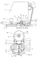
- the scrubber driers shown in the drawing have, in a known manner, a housing 1 in which the various units and containers are accommodated, such as in particular the suction fan, separating devices for the dirt picked up, the storage container and the metering device for the scrubbing liquid and the like.
- the housing 1 is supported by three rollers on the floor 2, two rollers as non-steerable rollers 3 and the third roller as one vertical axis swivel castor 4 are formed.
- two handles 5 are arranged at the rear end thereof, on which the operator guides the scrubber-drier.
- the control panel 6 arranged between the handles 5 carries the operating and control instruments necessary for the operation.
- the structure of the scrubber-drier shown is identical to that according to the prior art.
- the scrubber drier according to FIGS. 1 to 3 and 5 thus has a main brush 7 designed as a plate brush, which is covered by a main brush hood 8.
- the main brush hood is supported by the housing by means of a hollow carrier 9, the drive shaft, with which the drive power is transmitted from the main brush drive 10 to the main brush 7, running inside the hollow carrier.
- the suction head 12 is attached to the rear end of the scrubber-drier according to FIGS.
- the suction head 12 is surmounted on both sides by the suction bar 14, which slides on the floor with a rubber lip and supplies the liquid to be sucked up to the suction head.
- the suction bar 14 protrudes slightly from the housing 1 of the scrubber drier on both sides in order to ensure that the entire liquid film is securely picked up.
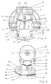
- the scrubber-dryer shown in FIGS. 1, 2, 3 and 5 has two pivot pins 15 on the underside of its chassis, to each of which a pivot arm 16 is pivotably articulated about a vertical axis. Opposite the articulation point of each swivel arm 16, this carries an additional brush device consisting of an additional brush 17 designed as a plate brush, an additional brush hood 18 covering it, and an additional brush drive 19 , which is attached to the outside of the additional brush hood 18 and is pressed inside by an additional support 21, which is also attached to the additional brush hood, against the floor 2 (in FIG.
- the squeegee 20 is shown broken with the omission of its rear section, so that the components located further inside (cover plate 23, swivel castor 4) can be seen).
- the two scraper strips 20 run diagonally backwards, inside, and in this way convey the water film left by the additional brushes into the central area covered by the suction strip 14.
- Each of the two swivel arms 16 is pressed sideways by a spring strut 22, provided that the additional brush hoods do not encounter an obstacle.
- the right auxiliary brush in its retracted position (B) and the left auxiliary brush in its half-extended position are shown in FIG. 2 only to illustrate the different possible positions of the auxiliary brushes.
- a cover plate 23 extends over the entire width of the main brush of the scrubber-drier according to FIGS. 1, 2 and 4 and is attached to the cover plate by means of a holder 24 riveted to it Bottom of the housing 1 is fixed by screws 25.
- the suspension of the cover plate 23 is such that it is guided at a slight distance above the bottom 2.
- the front edge 26 of the cover plate 23 is bent upwards in order to allow the cover plate to deflect upwards when driving onto a possible obstacle or driving over a bump.
- the auxiliary brushes are guided as described in connection with FIGS. 1 and 2.
- the embodiment shown in FIG. 3 has two suction elements designed as suction feet 46 in the direction of travel behind the additional brushes.
- the suction feet are firmly attached to the additional brush hoods 18; their structure corresponds essentially to that of the suction bar 14.
- the nozzle 47 for connecting the suction hose is arranged on each squeegee in its inner third.
- the suction feet 46 are coupled via the corresponding suction hoses to the suction fan, to which the suction bar 14 is also connected.
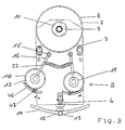
- both the main brush 7 and the additional brushes 17 are designed as roller brushes with a horizontal, transverse axis of rotation.
- the main brush 7 is received in a downwardly open, U-shaped frame 41 which is fastened to the underside of the housing by means of two carriers 42.
- the additional brushes 17 are also mounted in corresponding U-shaped frames 43 which are open at the bottom and which in turn each have one two links 44 existing parallelogram guide are hinged to the frame 41 of the main brush 7.
- a spring strut 22 is assigned to each of the parallelogram guides, which is prestressed between a central, articulation point 45 fixed to the housing and the respective inner of the two links 44 and presses the additional brush units sideways outwards.
- the wiper strips 20 are fixedly connected at their outer ends to the respective outer section of the corresponding frame 43.
- guide eyes 31 are provided on the housing, in which the respective scraper strip 20 is guided so as to be longitudinally displaceable. This results in an adaptation of the guide strips to the respective position of the additional brush unit in such a way that an effective transport of the water film inwards is ensured regardless of the position of the additional brushes.
- Longitudinal guides can also be provided to hold the inner ends of the squeegees. These each consist of a guide rod that is firmly connected to the chassis and a sliding piece that slides on the latter and with which the inner end of the respective squeegee is firmly connected.
- the two guide rods run diagonally backwards, towards each other on the inside, in order to ensure effective transport of the water film inwards.
- deflection rails 33 are arranged in the working direction in front of the additional brush units, which prevent table legs or the like from getting between the housing and an additional brush.
- Each deflector rail 33 is with their front end articulated to a mounting point 34 provided on the chassis.
- the rear end of each deflection rail 33 is guided in a longitudinally displaceable manner in a guide sleeve 35, which is attached to the respective additional brush hood 18; in this way, the deflection rails 33 can be optimally adapted to the respective position of the corresponding additional brush unit.
- the scrubber drier shown in FIG. 5 essentially corresponds to that according to FIG. 3. It differs from the latter by a different design of the elements which serve to extract the water film.
- the suction feet 46 coupled with the positionally variable brushes 17 represent a telescopic extension of the central suction bar 14.
- the suction bar 14 encompasses the two suction feet 46, which are fastened to the additional brush hoods 18 by means of holding brackets 48. At the outer ends 49 of the suction bar 14, this is sealed off from the suction feet by means of a respective seal so that the inflow of additional air into the suction bar 14 is prevented.
- the suction bar 14, which is arranged firmly on the chassis is coupled to the suction fan in the manner already described via a suction hose 13; a separate connection of the suction feet 46 to the suction fan is not necessary.
Landscapes
- Soil Working Implements (AREA)
- Cleaning In General (AREA)
- Disintegrating Or Milling (AREA)
- Air Bags (AREA)
- Vehicle Cleaning, Maintenance, Repair, Refitting, And Outriggers (AREA)
- Drying Of Solid Materials (AREA)
- Treatment Of Fiber Materials (AREA)
- Finish Polishing, Edge Sharpening, And Grinding By Specific Grinding Devices (AREA)
- Perforating, Stamping-Out Or Severing By Means Other Than Cutting (AREA)
- Machine Tool Units (AREA)
- Turning (AREA)
- Cultivation Receptacles Or Flower-Pots, Or Pots For Seedlings (AREA)
- Vehicle Body Suspensions (AREA)
- Lifting Devices For Agricultural Implements (AREA)
Claims (15)
- Machine pour le nettoyage de sols comportant un châssis, un dispositif de traitement du sol (7,8,9,10,17,19), qui comprend un dispositif de frottement, et un dispositif d'aspiration (12,13,14; 46,47), et dans laquelle le dispositif de traitement du sol comporte au moins deux corps frottants rotatifs (7,17), la position de l'un au moins (17) de ces corps étant variable pour modifier la largeur de travail du dispositif de traitement du sol et dans laquelle le dispositif d'aspiration comporte au moins une tête d'aspiration (12) disposée à proximité du sol en arrière du dispositif de traitement du sol dans la direction de travail, et un élément d'aspiration (46), dont la position est variable, ou une barrette formant racle (20), dont la position est variable et qui envoie des particules et/ou des liquides, situés sur le sol, à la tête d'aspiration (12) ou à une barrette d'aspiration (14) reliée à cette tête, est accouplé au ou à chaque corps de traitement, dont la position est variable, de sorte que la largeur de travail du dispositif d'aspiration est automatiquement adaptée à la largeur de travail du dispositif de traitement du sol, et dans laquelle en outre le au moins un corps de traitement (17) à position variable est suspendu de telle sorte qu'il est situé en arrière du point d'articulation dans la direction de travail, au moins dans la cas d'une faible largeur de travail de sorte qu'il bascule en arrière et vers l'intérieur dans le cas d'une réduction de la largeur de travail,
caractérisée en ce
que pour la modification de position de chaque corps de traitement (17) à position variable, il est prévu une unité hydraulique à piston et cylindre. - Machine pour le traitement de sols comportant un châssis, un dispositif de traitement du sol (7,8,9,10,17,19), qui comprend un dispositif de ponçage ou de polissage, et un dispositif d'aspiration (12,13,14; 46,47), et dans laquelle le dispositif de traitement du sol comporte au moins deux corps de traitement rotatifs (7,17), qui sont agencés sous la forme de corps de ponçage ou de polissage, et la position de l'un au moins (17) de ce corps étant variable pour modifier la largeur de travail du dispositif de traitement du sol, et dans laquelle le dispositif d'aspiration comporte au moins une tête d'aspiration (12) disposée à proximité du sol en arrière du dispositif de traitement du sol dans la direction de travail, et un élément d'aspiration (46), dont la position est variable, ou une barrette formant racle (20), dont la position est variable et qui envoie des particules et/ou des liquides, situés sur le sol, à la tête d'aspiration (12) ou à une barrette d'aspiration (14) reliée à cette tête, est accouplé au ou à chaque corps de traitement, dont la position est variable, de sorte que la largeur de travail du dispositif d'aspiration est automatiquement adaptée à la largeur de travail du dispositif de traitement du sol,
caractérisée en ce
que le au moins un corps de traitement (17) à position variable est suspendu de telle sorte qu'il est situé en arrière du point d'articulation dans la direction de travail, au moins dans le cas d'une faible largeur de travail de sorte qu'il pivote vers l'intérieur et vers l'arrière dans le cas d'une réduction de la largeur de travail. - Machine de traitement du sol selon la revendication 1 ou 2, caractérisée en ce
que le au moins un corps de traitement (17) à position variable est articulé au châssis au moyen d'un bras basculant (16), qui pivote autour d'un axe vertical. - Machine de traitent du sol selon la revendication 1 ou 2,
caractérisée en ce
que le au moins un corps de traitement (17) à position variable est articulé sur le boîtier (1), à l'aide d'un système de guidage en forme de parallélogramme (44). - Machine de traitement du sol selon la revendication 1 ou 2, caractérisée en ce que chaque corps de traitement (17) à position variable est amené automatiquement, par un élément de ressort (22), dans la position déployée (A).
- Machine de traitement du sol selon la revendication 2, caractérisée en ce qu'une unité hydraulique à piston et cylindre est prévue pour modifier la position du corps de traitement (17) à position variable.
- Machine de traitement du sol selon la revendication 1 ou 2, caractérisée en ce
que dans la zone du bord avant d'au moins un corps de traitement à position variable est prévu un étrier de palpage, qui agit sur au moins un interrupteur à poussoir, qui, lors de la rencontre d'un obstacle, commande le changement de position du corps de travail correspondant dans le sens d'une réduction de la largeur de travail. - Machine de traitement du sol selon la revendication 1 ou 2, caractérisée en ce
qu'un rail de butée (33) est prévu en avant de chaque corps de traitement (17) à position variable, dans la direction de travail. - Machine de traitement du sol selon la revendication 1 ou 2, caractérisée en ce
qu'il est prévu deux corps de traitement (17) à position variable, qui sont suspendus respectivement d'un côté de manière à pouvoir être déplacés au-delà de la zone de travail d'un corps de traitement fixe (7). - Machine de traitement du sol selon la revendication 9, caractérisée en ce
que l'articulation des deux corps de traitement (17) à position variable est symétrique par rapport à l'axe longitudinal de la machine. - Machine de traitement du sol selon la revendication 9, caractérisée en ce que les deux corps de traitement (17) à position variable sont disposés d'une manière étagée l'un derrière l'autre dans la direction longitudinale de la machine.
- Machine de traitement du sol selon la revendication 1 ou 2, caractérisée en ce
qu'en arrière de chaque corps de traitement (17) à position variable est prévu un élément d'aspiration (46), qui est raccordé à un aspirateur central. - Machine de traitement du sol selon la revendication 1 ou 2, caractérisée en ce
que l'extrémité intérieure de chaque barrette de raclage (20) ou de chaque élément d'aspiration est guidée dans un guide longitudinal (31). - Machine de traitement du sol selon la revendication 1 ou 2, caractérisée en ce
que les barrettes formant racles (20) ou les éléments d'aspiration (46), qui sont accouplés aux corps de traitement (17) à position variable, représentent des prolongements télescopiques d'une barrette centrale d'aspiration (14). - Machine de traitement du sol selon la revendication 1 ou 2, caractérisée en ce
que les éléments d'aspiration (46) à longueur variable ou les barrettes de raclage (20) sont disposés directement en arrière des corps de traitement à position variable.
Applications Claiming Priority (7)
| Application Number | Priority Date | Filing Date | Title |
|---|---|---|---|
| DE19914103087 DE4103087C1 (en) | 1991-02-01 | 1991-02-01 | Scrubbing vacuum cleaner with following auxiliary brush - has scrapingstrips returning residual liq. from latter to suction mouth |
| DE4103087 | 1991-02-01 | ||
| DE9115713U DE9115713U1 (de) | 1991-02-01 | 1991-12-18 | Scheuersaugmaschine |
| DE9115713U | 1991-12-18 | ||
| DE4200630 | 1992-01-13 | ||
| DE19924200630 DE4200630A1 (de) | 1991-02-01 | 1992-01-13 | Bodenreinigungsmaschine |
| EP92903744A EP0569430B1 (fr) | 1991-02-01 | 1992-01-30 | Machine de traitement de planchers |
Related Parent Applications (3)
| Application Number | Title | Priority Date | Filing Date |
|---|---|---|---|
| EP92903744.8 Division | 1992-01-30 | ||
| EP92903744A Division EP0569430B1 (fr) | 1991-02-01 | 1992-01-30 | Machine de traitement de planchers |
| EP92903744A Division-Into EP0569430B1 (fr) | 1991-02-01 | 1992-01-30 | Machine de traitement de planchers |
Publications (2)
| Publication Number | Publication Date |
|---|---|
| EP0580186A1 EP0580186A1 (fr) | 1994-01-26 |
| EP0580186B1 true EP0580186B1 (fr) | 1995-08-23 |
Family
ID=27202152
Family Applications (2)
| Application Number | Title | Priority Date | Filing Date |
|---|---|---|---|
| EP93113787A Expired - Lifetime EP0580186B1 (fr) | 1991-02-01 | 1992-01-30 | Machine de nettoyage du sol |
| EP92903744A Expired - Lifetime EP0569430B1 (fr) | 1991-02-01 | 1992-01-30 | Machine de traitement de planchers |
Family Applications After (1)
| Application Number | Title | Priority Date | Filing Date |
|---|---|---|---|
| EP92903744A Expired - Lifetime EP0569430B1 (fr) | 1991-02-01 | 1992-01-30 | Machine de traitement de planchers |
Country Status (11)
| Country | Link |
|---|---|
| US (1) | US5524320A (fr) |
| EP (2) | EP0580186B1 (fr) |
| JP (1) | JP3234220B2 (fr) |
| AT (2) | ATE113450T1 (fr) |
| AU (1) | AU664026B2 (fr) |
| CA (1) | CA2103918C (fr) |
| DE (4) | DE9218728U1 (fr) |
| DK (2) | DK0580186T3 (fr) |
| ES (2) | ES2064165T3 (fr) |
| HU (1) | HUT67353A (fr) |
| WO (1) | WO1992013480A1 (fr) |
Families Citing this family (52)
| Publication number | Priority date | Publication date | Assignee | Title |
|---|---|---|---|---|
| US5265300A (en) * | 1992-01-13 | 1993-11-30 | Aar Corp. | Floor scrubber |
| FR2735005B1 (fr) * | 1995-06-07 | 1997-07-18 | France Mat Ind | Machine pour le nettoyage des sols |
| DE69701539T2 (de) * | 1996-03-01 | 2000-09-14 | Unilever N.V., Rotterdam | Bodenreinigungsvorrichtung |
| EP0792614B1 (fr) * | 1996-03-01 | 2000-03-29 | Unilever N.V. | Appareil pour nettoyer les sols |
| ES2162185T3 (es) * | 1996-03-01 | 2001-12-16 | Unilever Nv | Aparato para limpiar el suelo. |
| WO1997037579A1 (fr) * | 1996-04-11 | 1997-10-16 | Nilfisk Schwamborn Gmbh | Calotte aspirante pour machines de nettoyage de sols par voie humide |
| DE29607848U1 (de) * | 1996-04-30 | 1997-09-04 | Diethelm & Co. AG, Zürich | Bodenreinigungsmaschine, insbesondere Scheuersaugmaschine |
| US5742975A (en) * | 1996-05-06 | 1998-04-28 | Windsor Industries, Inc. | Articulated floor scrubber |
| US5623743A (en) * | 1996-06-04 | 1997-04-29 | Clarke Industries, Inc. | Mobile surface scrubber solution recovery system |
| DE19713123C1 (de) * | 1997-03-27 | 1998-10-29 | Hefter Georg Maschb | Bodenbearbeitungsmaschine |
| SE9803535L (sv) * | 1998-10-14 | 2000-04-15 | Noton Ab | Städmaskin |
| EP1143843B1 (fr) * | 1999-01-20 | 2006-09-20 | ZACHHUBER, Kurt | Machine pour traiter les sols |
| US6557207B2 (en) | 2000-08-22 | 2003-05-06 | Alto U.S. Inc. | Squeegee assembly for a floor surface treatment apparatus |
| US6763544B2 (en) | 2000-08-22 | 2004-07-20 | Alto Us, Inc. | Apparatus for treating a floor surface |
| US6760947B2 (en) | 2000-08-22 | 2004-07-13 | Alto U.S. Inc. | Apparatus for treating a floor surface utilizing a handle mounted traverse switch |
| US7261623B1 (en) | 2001-07-23 | 2007-08-28 | Onfloor Technologies, L.L.C. | Wood floor sanding machine |
| US6684452B2 (en) | 2001-10-17 | 2004-02-03 | Nilfisk-Advance, Inc. | Dual cleaning mode carpet extractor |
| US7533435B2 (en) | 2003-05-14 | 2009-05-19 | Karcher North America, Inc. | Floor treatment apparatus |
| US20120096671A1 (en) | 2010-10-26 | 2012-04-26 | Karcher North America, Inc. | Floor cleaning apparatus employing a combined sweeper and vaccum assembly |
| US8302240B2 (en) * | 2009-07-29 | 2012-11-06 | Karcher North America, Inc. | Selectively adjustable steering mechanism for use on a floor cleaning machine |
| US7707682B2 (en) * | 2003-12-19 | 2010-05-04 | Techtronic Floor Care Technology Limited | Cleaning machine for cleaning a surface with edge cleaning capability |
| US7185397B2 (en) * | 2004-04-09 | 2007-03-06 | Alto U.S. Inc. | Floor cleaning machine |
| USD533320S1 (en) | 2004-11-11 | 2006-12-05 | Castle Rock Industries, Inc. | Floor treatment device |
| DE102005018882A1 (de) * | 2005-04-22 | 2006-11-02 | Hako-Werke Gmbh | Bodenreinigungsmaschine |
| AU2006330788B2 (en) | 2005-12-22 | 2011-05-19 | Diversey, Inc. | Squeegee assembly for a floor cleaning machine |
| USD613472S1 (en) | 2006-02-01 | 2010-04-06 | Johnsondiversey, Inc. | Combined squeegee and support frame |
| DE102006037453B4 (de) * | 2006-08-10 | 2014-12-11 | Andreas Stihl Ag & Co. Kg | Handgeführtes, motorgetriebenes Kehrgerät |
| KR20140123110A (ko) * | 2007-05-09 | 2014-10-21 | 아이로보트 코퍼레이션 | 소형 자율 커버리지 로봇 |
| WO2009004320A1 (fr) * | 2007-06-29 | 2009-01-08 | Numatic International Limited | Machine de nettoyage des sols |
| US8393937B2 (en) * | 2007-07-20 | 2013-03-12 | Onfloor Technologies, L.L.C. | Floor finishing machine |
| US8282445B2 (en) | 2007-07-20 | 2012-10-09 | Onfloor Technologies, L.L.C. | Floor finishing apparatus |
| JP5278650B2 (ja) * | 2007-12-26 | 2013-09-04 | ニチユ三菱フォークリフト株式会社 | 燃料タンク搭載機構及び該機構を備えた産業車両 |
| JP5243879B2 (ja) * | 2008-08-04 | 2013-07-24 | 富士重工業株式会社 | 清掃ロボットのサイドブラシ支持装置 |
| GB0912496D0 (en) * | 2009-07-17 | 2009-08-26 | Numatic Int Ltd | Floor cleaning machine |
| US8966693B2 (en) | 2009-08-05 | 2015-03-03 | Karcher N. America, Inc. | Method and apparatus for extended use of cleaning fluid in a floor cleaning machine |
| USD654234S1 (en) | 2010-12-08 | 2012-02-14 | Karcher North America, Inc. | Vacuum bag |
| US9016290B2 (en) * | 2011-02-24 | 2015-04-28 | Joseph E. Kovarik | Apparatus for removing a layer of sediment which has settled on the bottom of a pond |
| US12158019B2 (en) | 2011-02-24 | 2024-12-03 | Pond Mower, LLC | Apparatus for removing a layer of sediment which has settled on the bottom of a large water body |
| US8978190B2 (en) | 2011-06-28 | 2015-03-17 | Karcher North America, Inc. | Removable pad for interconnection to a high-speed driver system |
| US9554683B2 (en) * | 2012-05-03 | 2017-01-31 | Nss Enterprises, Inc. | Dual drive floor scrubber |
| DE202012010452U1 (de) * | 2012-10-30 | 2014-01-31 | Wetrok Ag | Bodenreinigungsvorrichtung |
| EP3013205A1 (fr) | 2013-06-28 | 2016-05-04 | Alfred Kärcher GmbH & Co. KG | Machine de nettoyage de sol autoportée mobile et procédé de positionnement d'une rampe aspirante d'une machine de nettoyage de sol autoportée mobile |
| DE102014102812A1 (de) * | 2014-03-04 | 2015-09-10 | Alfred Kärcher Gmbh & Co. Kg | Kehrmaschine und Verfahren zum Betreiben einer Kehrmaschine |
| CN104939368A (zh) * | 2015-07-02 | 2015-09-30 | 顾锦明 | 一种防水雨衣门襟及其缝制方法 |
| EP3618676B1 (fr) | 2017-05-04 | 2023-09-20 | Alfred Kärcher SE & Co. KG | Appareil de nettoyage de sol et méthode de nettoyage d'une surface au sol |
| CN108670132B (zh) * | 2018-03-29 | 2024-11-22 | 深圳市凌晨知识产权运营有限公司 | 一种吸水耙升降装置及地面清洁机 |
| CN109078878A (zh) * | 2018-08-02 | 2018-12-25 | 江苏师范大学 | 一种往复擦拭清扫装置 |
| USD907868S1 (en) | 2019-01-24 | 2021-01-12 | Karcher North America, Inc. | Floor cleaner |
| US12343843B2 (en) | 2021-10-22 | 2025-07-01 | Diamond Productions Ltd. | Automatic detection system for floor treating machines |
| US11969127B2 (en) | 2021-10-22 | 2024-04-30 | Diamond Productions Ltd. | Automatic detection system for combination burnisher, polisher, and scrubber |
| US12232671B2 (en) | 2021-10-22 | 2025-02-25 | Diamond Productions Ltd. | Automatic detection system for combination burnisher, polisher, and scrubber |
| CN118873047A (zh) * | 2024-08-16 | 2024-11-01 | 苏州展翘电器有限公司 | 一种角度自适应调整式滚刷 |
Family Cites Families (10)
| Publication number | Priority date | Publication date | Assignee | Title |
|---|---|---|---|---|
| US3277511A (en) * | 1964-04-15 | 1966-10-11 | Nat Super Service Company | Adjustable width floor treating machine |
| US3345671A (en) * | 1966-01-11 | 1967-10-10 | Ross D Wilson | Floor scrubbing and polishing machine |
| US3866541A (en) * | 1972-03-24 | 1975-02-18 | Connor James M O | Self-propelled floor cleaning apparatus with movable brush |
| DE2323588B2 (de) * | 1973-05-10 | 1978-11-09 | Woma Apparatebau Wolfgang Maasberg & Co Gmbh, 4100 Duisburg | Als Fahrzeug ausgebildeter Waschsauger zum Reinigen von Straßen u.a. Flächen |
| GB1446121A (en) * | 1974-05-06 | 1976-08-18 | Sterling Winthrop Group Ltd | Floor maintenance machines |
| US4492002A (en) * | 1980-09-12 | 1985-01-08 | Wetrok, Inc. | Floor cleaning machine |
| US4490873A (en) * | 1983-10-24 | 1985-01-01 | Stratton Harry M | Floating-brush assembly for use with floor-scrubbing and polishing machines |
| FR2573976A1 (fr) | 1984-03-27 | 1986-06-06 | Peyrigue Serge | Appareil autolaveur |
| FR2653359A1 (fr) * | 1989-10-19 | 1991-04-26 | Protee | Engin pour nettoyer une surface, procede de nettoyage utilisant cet engin, et application de ce procede au nettoyage du sol d'un vehicule de transport en commun. |
| FR2657769B1 (fr) * | 1990-02-07 | 1994-07-29 | Miroir 2000 Sarl | Machine automotrice de traitement de surface au moyen d'agents liquides et de brosses rotatives. |
-
1992
- 1992-01-30 US US08/094,138 patent/US5524320A/en not_active Expired - Lifetime
- 1992-01-30 ES ES92903744T patent/ES2064165T3/es not_active Expired - Lifetime
- 1992-01-30 AU AU11804/92A patent/AU664026B2/en not_active Ceased
- 1992-01-30 WO PCT/EP1992/000198 patent/WO1992013480A1/fr not_active Ceased
- 1992-01-30 AT AT92903744T patent/ATE113450T1/de not_active IP Right Cessation
- 1992-01-30 DE DE9218728U patent/DE9218728U1/de not_active Expired - Lifetime
- 1992-01-30 CA CA002103918A patent/CA2103918C/fr not_active Expired - Fee Related
- 1992-01-30 EP EP93113787A patent/EP0580186B1/fr not_active Expired - Lifetime
- 1992-01-30 AT AT93113787T patent/ATE126683T1/de not_active IP Right Cessation
- 1992-01-30 JP JP50325392A patent/JP3234220B2/ja not_active Expired - Fee Related
- 1992-01-30 HU HU9302182A patent/HUT67353A/hu unknown
- 1992-01-30 DE DE9218729U patent/DE9218729U1/de not_active Expired - Lifetime
- 1992-01-30 ES ES93113787T patent/ES2048703T3/es not_active Expired - Lifetime
- 1992-01-30 DE DE59203398T patent/DE59203398D1/de not_active Expired - Lifetime
- 1992-01-30 EP EP92903744A patent/EP0569430B1/fr not_active Expired - Lifetime
- 1992-01-30 DE DE59200738T patent/DE59200738D1/de not_active Expired - Fee Related
- 1992-01-30 DK DK93113787.1T patent/DK0580186T3/da active
- 1992-01-30 DK DK92903744.8T patent/DK0569430T3/da active
Also Published As
| Publication number | Publication date |
|---|---|
| HUT67353A (en) | 1995-03-28 |
| AU1180492A (en) | 1992-09-07 |
| HU9302182D0 (en) | 1993-11-29 |
| DK0580186T3 (da) | 1995-09-18 |
| DK0569430T3 (da) | 1994-11-28 |
| ES2048703T3 (es) | 1996-10-01 |
| DE9218728U1 (de) | 1995-05-18 |
| DE59203398D1 (de) | 1995-09-28 |
| ATE113450T1 (de) | 1994-11-15 |
| JP3234220B2 (ja) | 2001-12-04 |
| DE59200738D1 (de) | 1994-12-08 |
| AU664026B2 (en) | 1995-11-02 |
| ATE126683T1 (de) | 1995-09-15 |
| DE9218729U1 (de) | 1995-05-18 |
| US5524320A (en) | 1996-06-11 |
| WO1992013480A1 (fr) | 1992-08-20 |
| ES2048703T1 (es) | 1994-04-01 |
| EP0580186A1 (fr) | 1994-01-26 |
| ES2064165T3 (es) | 1995-01-16 |
| JPH06504692A (ja) | 1994-06-02 |
| EP0569430A1 (fr) | 1993-11-18 |
| EP0569430B1 (fr) | 1994-11-02 |
| CA2103918C (fr) | 1999-11-30 |
| CA2103918A1 (fr) | 1992-08-02 |
Similar Documents
| Publication | Publication Date | Title |
|---|---|---|
| EP0569430B1 (fr) | Machine de traitement de planchers | |
| EP3206551B1 (fr) | Machine de nettoyage de surfaces | |
| EP3033984B1 (fr) | Appareil de traitement de sol a guidage manuel | |
| EP2098150B1 (fr) | Bas d'aspiration pour un aspirateur de sol | |
| WO2012171579A1 (fr) | Balayeuse de voirie comprenant un dispositif de réglage de disque de brosse | |
| EP1964976B1 (fr) | Balayeuse à projection par le haut | |
| DE69718007T2 (de) | Vorrichtung und verfahren zum reinigen von flexographischen druckplatten | |
| EP3092932B1 (fr) | Dispositif de nettoyage du sol | |
| DE69701539T2 (de) | Bodenreinigungsvorrichtung | |
| DE19715435C2 (de) | Überkopfwerfer-Reinigungsmaschine | |
| DE4103087C1 (en) | Scrubbing vacuum cleaner with following auxiliary brush - has scrapingstrips returning residual liq. from latter to suction mouth | |
| EP3415067B1 (fr) | Dispositif formant balai latéral pour une machine de nettoyage du sol | |
| DE2145633A1 (de) | Bodenpflegemaschine | |
| EP3013205A1 (fr) | Machine de nettoyage de sol autoportée mobile et procédé de positionnement d'une rampe aspirante d'une machine de nettoyage de sol autoportée mobile | |
| DE4200630A1 (de) | Bodenreinigungsmaschine | |
| DE3017485A1 (de) | Vorrichtung zur reinigung von flaechen wie bodenflaechen, insbesondere von hartbodenflaechen, sowie von wandflaechen, fassadenflaechen o.dgl. | |
| DE19748276C1 (de) | Fahrbares Bodenreinigungsgerät | |
| EP4195988B1 (fr) | Appareil de traitement de plancher | |
| EP0659054B1 (fr) | Machine de traitement de sols | |
| DE3145946C2 (de) | Maschine zum Reinigen von Wand- und Glasflächen | |
| DE3542631A1 (de) | Reinigungsgeraet fuer hartflaechen | |
| DE9115578U1 (de) | Scheuersaugmaschine | |
| EP1612335A2 (fr) | Dispositif de balayage automobile | |
| EP1143843B1 (fr) | Machine pour traiter les sols | |
| DE9410119U1 (de) | Bodenreinigungsmaschine |
Legal Events
| Date | Code | Title | Description |
|---|---|---|---|
| PUAI | Public reference made under article 153(3) epc to a published international application that has entered the european phase |
Free format text: ORIGINAL CODE: 0009012 |
|
| 17P | Request for examination filed |
Effective date: 19931130 |
|
| AC | Divisional application: reference to earlier application |
Ref document number: 569430 Country of ref document: EP |
|
| AK | Designated contracting states |
Kind code of ref document: A1 Designated state(s): AT BE CH DE DK ES FR GB IT LI NL SE |
|
| TCNL | Nl: translation of patent claims filed | ||
| 17Q | First examination report despatched |
Effective date: 19940923 |
|
| GRAA | (expected) grant |
Free format text: ORIGINAL CODE: 0009210 |
|
| AC | Divisional application: reference to earlier application |
Ref document number: 569430 Country of ref document: EP |
|
| AK | Designated contracting states |
Kind code of ref document: B1 Designated state(s): AT BE CH DE DK ES FR GB IT LI NL SE |
|
| REF | Corresponds to: |
Ref document number: 126683 Country of ref document: AT Date of ref document: 19950915 Kind code of ref document: T |
|
| REG | Reference to a national code |
Ref country code: DK Ref legal event code: T3 |
|
| GBT | Gb: translation of ep patent filed (gb section 77(6)(a)/1977) |
Effective date: 19950821 |
|
| ITF | It: translation for a ep patent filed | ||
| REF | Corresponds to: |
Ref document number: 59203398 Country of ref document: DE Date of ref document: 19950928 |
|
| ET | Fr: translation filed | ||
| REG | Reference to a national code |
Ref country code: ES Ref legal event code: BA2A Ref document number: 2048703 Country of ref document: ES Kind code of ref document: T3 |
|
| PLBE | No opposition filed within time limit |
Free format text: ORIGINAL CODE: 0009261 |
|
| 26N | No opposition filed | ||
| REG | Reference to a national code |
Ref country code: ES Ref legal event code: FG2A Ref document number: 2048703 Country of ref document: ES Kind code of ref document: T3 |
|
| REG | Reference to a national code |
Ref country code: ES Ref legal event code: FG2A Ref document number: 2048703 Country of ref document: ES Kind code of ref document: T3 |
|
| REG | Reference to a national code |
Ref country code: FR Ref legal event code: TP |
|
| NLS | Nl: assignments of ep-patents |
Owner name: GEORG HEFTER GDBR |
|
| BECA | Be: change of holder's address |
Free format text: 980423 GEORG *HEFTER GDBR:BERNAUER STRASSE 71, D-83209 PRIEN/CHIEMSEE |
|
| REG | Reference to a national code |
Ref country code: GB Ref legal event code: 732E |
|
| REG | Reference to a national code |
Ref country code: GB Ref legal event code: IF02 |
|
| REG | Reference to a national code |
Ref country code: CH Ref legal event code: PCAR Free format text: ISLER & PEDRAZZINI AG;POSTFACH 1772;8027 ZUERICH (CH) |
|
| PGFP | Annual fee paid to national office [announced via postgrant information from national office to epo] |
Ref country code: SE Payment date: 20080124 Year of fee payment: 17 Ref country code: GB Payment date: 20080123 Year of fee payment: 17 |
|
| PGFP | Annual fee paid to national office [announced via postgrant information from national office to epo] |
Ref country code: FR Payment date: 20080118 Year of fee payment: 17 |
|
| PGFP | Annual fee paid to national office [announced via postgrant information from national office to epo] |
Ref country code: BE Payment date: 20080123 Year of fee payment: 17 |
|
| EUG | Se: european patent has lapsed | ||
| GBPC | Gb: european patent ceased through non-payment of renewal fee |
Effective date: 20090130 |
|
| REG | Reference to a national code |
Ref country code: FR Ref legal event code: ST Effective date: 20091030 |
|
| PG25 | Lapsed in a contracting state [announced via postgrant information from national office to epo] |
Ref country code: GB Free format text: LAPSE BECAUSE OF NON-PAYMENT OF DUE FEES Effective date: 20090130 |
|
| PG25 | Lapsed in a contracting state [announced via postgrant information from national office to epo] |
Ref country code: BE Free format text: LAPSE BECAUSE OF NON-PAYMENT OF DUE FEES Effective date: 20090131 |
|
| PG25 | Lapsed in a contracting state [announced via postgrant information from national office to epo] |
Ref country code: FR Free format text: LAPSE BECAUSE OF NON-PAYMENT OF DUE FEES Effective date: 20090202 |
|
| PGFP | Annual fee paid to national office [announced via postgrant information from national office to epo] |
Ref country code: DK Payment date: 20110125 Year of fee payment: 20 |
|
| PG25 | Lapsed in a contracting state [announced via postgrant information from national office to epo] |
Ref country code: SE Free format text: LAPSE BECAUSE OF NON-PAYMENT OF DUE FEES Effective date: 20090131 |
|
| PGFP | Annual fee paid to national office [announced via postgrant information from national office to epo] |
Ref country code: CH Payment date: 20110125 Year of fee payment: 20 Ref country code: AT Payment date: 20110120 Year of fee payment: 20 Ref country code: NL Payment date: 20110119 Year of fee payment: 20 Ref country code: IT Payment date: 20110126 Year of fee payment: 20 |
|
| PGFP | Annual fee paid to national office [announced via postgrant information from national office to epo] |
Ref country code: DE Payment date: 20110325 Year of fee payment: 20 Ref country code: ES Payment date: 20110121 Year of fee payment: 20 |
|
| REG | Reference to a national code |
Ref country code: DE Ref legal event code: R071 Ref document number: 59203398 Country of ref document: DE |
|
| REG | Reference to a national code |
Ref country code: DE Ref legal event code: R071 Ref document number: 59203398 Country of ref document: DE |
|
| REG | Reference to a national code |
Ref country code: NL Ref legal event code: V4 Effective date: 20120130 |
|
| REG | Reference to a national code |
Ref country code: CH Ref legal event code: PL |
|
| REG | Reference to a national code |
Ref country code: DK Ref legal event code: EUP |
|
| REG | Reference to a national code |
Ref country code: AT Ref legal event code: MK07 Ref document number: 126683 Country of ref document: AT Kind code of ref document: T Effective date: 20120130 |
|
| PG25 | Lapsed in a contracting state [announced via postgrant information from national office to epo] |
Ref country code: DE Free format text: LAPSE BECAUSE OF EXPIRATION OF PROTECTION Effective date: 20120131 |
|
| REG | Reference to a national code |
Ref country code: ES Ref legal event code: FD2A Effective date: 20120510 |
|
| PG25 | Lapsed in a contracting state [announced via postgrant information from national office to epo] |
Ref country code: ES Free format text: LAPSE BECAUSE OF EXPIRATION OF PROTECTION Effective date: 20120131 |