EP3092932B1 - Dispositif de nettoyage du sol - Google Patents
Dispositif de nettoyage du sol Download PDFInfo
- Publication number
- EP3092932B1 EP3092932B1 EP16165923.0A EP16165923A EP3092932B1 EP 3092932 B1 EP3092932 B1 EP 3092932B1 EP 16165923 A EP16165923 A EP 16165923A EP 3092932 B1 EP3092932 B1 EP 3092932B1
- Authority
- EP
- European Patent Office
- Prior art keywords
- brush
- unit
- cleaning device
- brushes
- floor cleaning
- Prior art date
- Legal status (The legal status is an assumption and is not a legal conclusion. Google has not performed a legal analysis and makes no representation as to the accuracy of the status listed.)
- Active
Links
Images



Classifications
-
- A—HUMAN NECESSITIES
- A47—FURNITURE; DOMESTIC ARTICLES OR APPLIANCES; COFFEE MILLS; SPICE MILLS; SUCTION CLEANERS IN GENERAL
- A47L—DOMESTIC WASHING OR CLEANING; SUCTION CLEANERS IN GENERAL
- A47L11/00—Machines for cleaning floors, carpets, furniture, walls, or wall coverings
- A47L11/40—Parts or details of machines not provided for in groups A47L11/02 - A47L11/38, or not restricted to one of these groups, e.g. handles, arrangements of switches, skirts, buffers, levers
- A47L11/4052—Movement of the tools or the like perpendicular to the cleaning surface
-
- A—HUMAN NECESSITIES
- A47—FURNITURE; DOMESTIC ARTICLES OR APPLIANCES; COFFEE MILLS; SPICE MILLS; SUCTION CLEANERS IN GENERAL
- A47L—DOMESTIC WASHING OR CLEANING; SUCTION CLEANERS IN GENERAL
- A47L11/00—Machines for cleaning floors, carpets, furniture, walls, or wall coverings
- A47L11/02—Floor surfacing or polishing machines
- A47L11/10—Floor surfacing or polishing machines motor-driven
- A47L11/14—Floor surfacing or polishing machines motor-driven with rotating tools
- A47L11/16—Floor surfacing or polishing machines motor-driven with rotating tools the tools being disc brushes
- A47L11/161—Floor surfacing or polishing machines motor-driven with rotating tools the tools being disc brushes with supply of cleaning agents
-
- A—HUMAN NECESSITIES
- A47—FURNITURE; DOMESTIC ARTICLES OR APPLIANCES; COFFEE MILLS; SPICE MILLS; SUCTION CLEANERS IN GENERAL
- A47L—DOMESTIC WASHING OR CLEANING; SUCTION CLEANERS IN GENERAL
- A47L11/00—Machines for cleaning floors, carpets, furniture, walls, or wall coverings
- A47L11/29—Floor-scrubbing machines characterised by means for taking-up dirty liquid
- A47L11/30—Floor-scrubbing machines characterised by means for taking-up dirty liquid by suction
- A47L11/302—Floor-scrubbing machines characterised by means for taking-up dirty liquid by suction having rotary tools
- A47L11/305—Floor-scrubbing machines characterised by means for taking-up dirty liquid by suction having rotary tools the tools being disc brushes
-
- A—HUMAN NECESSITIES
- A47—FURNITURE; DOMESTIC ARTICLES OR APPLIANCES; COFFEE MILLS; SPICE MILLS; SUCTION CLEANERS IN GENERAL
- A47L—DOMESTIC WASHING OR CLEANING; SUCTION CLEANERS IN GENERAL
- A47L11/00—Machines for cleaning floors, carpets, furniture, walls, or wall coverings
- A47L11/34—Machines for treating carpets in position by liquid, foam, or vapour, e.g. by steam
-
- A—HUMAN NECESSITIES
- A47—FURNITURE; DOMESTIC ARTICLES OR APPLIANCES; COFFEE MILLS; SPICE MILLS; SUCTION CLEANERS IN GENERAL
- A47L—DOMESTIC WASHING OR CLEANING; SUCTION CLEANERS IN GENERAL
- A47L11/00—Machines for cleaning floors, carpets, furniture, walls, or wall coverings
- A47L11/40—Parts or details of machines not provided for in groups A47L11/02 - A47L11/38, or not restricted to one of these groups, e.g. handles, arrangements of switches, skirts, buffers, levers
- A47L11/4052—Movement of the tools or the like perpendicular to the cleaning surface
- A47L11/4055—Movement of the tools or the like perpendicular to the cleaning surface for lifting the tools to a non-working position
-
- A—HUMAN NECESSITIES
- A47—FURNITURE; DOMESTIC ARTICLES OR APPLIANCES; COFFEE MILLS; SPICE MILLS; SUCTION CLEANERS IN GENERAL
- A47L—DOMESTIC WASHING OR CLEANING; SUCTION CLEANERS IN GENERAL
- A47L11/00—Machines for cleaning floors, carpets, furniture, walls, or wall coverings
- A47L11/40—Parts or details of machines not provided for in groups A47L11/02 - A47L11/38, or not restricted to one of these groups, e.g. handles, arrangements of switches, skirts, buffers, levers
- A47L11/4052—Movement of the tools or the like perpendicular to the cleaning surface
- A47L11/4058—Movement of the tools or the like perpendicular to the cleaning surface for adjusting the height of the tool
Definitions
- the present invention relates to a floor cleaning device, comprising a brush device, which with respect to a working position of the brush device, which occupies this when cleaning a horizontal surface, rotatable about vertical axes of rotation and brushes at least partially surrounding and downwardly open brush housing, in which opens at least one steam outlet for steam generated by a steam generator and / or at least one hot water outlet, wherein the brush device in the working position of at least one suspension unit of the floor cleaning device, via which the floor cleaning device is fastened to a vehicle, with a pushing force for movement the brush device can be acted upon in a direction of travel, wherein with the brush device at least one force member of the floor cleaning device cooperates, and the brush device in a, based on the direction of travel, behind A region of the brush device against a force applied by at least one force member counterforce in the vertical direction relative to the at least one suspension unit can be raised.
- Sweepers attached to floor coverings often use rotary brush sweepers.
- a mechanical cleaning alone is often not enough.
- a commonly used method of chewing gum removal in practice is to heat the chewing gum by means of a heat source prior to mechanical removal and then remove it by means of a brush. Frequently, steam is used for this purpose. To improve the cleaning performance also washing-active substances are often used.
- a floor cleaning device for cleaning heavily soiled substrate which has a steaming section with a plurality of steam outlets and a brush arrangement arranged behind it with three brushes arranged on a rotatable brush plate.
- the floor cleaning device is pushed by the user over the surface to be cleaned.
- the brushes are mechanically connected to each other via a belt drive, wherein a rotation of the motor-driven brush plate leads to a rotation of the brushes.
- the brushes are attached to, opposite a brush housing oscillating movable brush holders. Steam is introduced into the brush housing.
- the brushes are rotatably mounted on the respective brush holder, but they are not rotationally driven.
- Each brush is individually displaceable relative to the respective brush holder in the vertical direction against a counterforce generated by a respective spring.
- the brushes On an uneven surface, the brushes, when viewed in the vertical direction, assume different positions so that the springs are compressed differently. Depending on the travel, the brushes are pressed against the ground due to the spring characteristic with different contact pressure, which is why the cleaning performance of the individual brushes is different for uneven floors.
- a floor cleaning device with a brush device according to the DE 20 2013 005 169 U1 known.
- the brush device is suspended here via a suspension unit on a vehicle, from which the brush device is pushed over the substrate to be cleaned.
- Uneven floors can only be accommodated to a limited extent by this floor cleaning device.
- driving over hills or pans and overcoming step-like obstacles, such as curbs it can lead to a high load of individual brushes, and subsequently to a heavy wear of the brushes.
- a floor cleaning device of the type mentioned goes out of the US 5,992,968 A out.
- the rear region of the brush device of the floor cleaning device can be raised in the vertical direction against a counterforce applied by a force element designed as a spiral or gas pressure spring. This allows a deflection of the brush device relative to the suspension unit in the vertical direction when driving on bumps.
- a similar floor cleaning device with a trained as a spiral spring force member is in the US 2013/0212819 A1 shown.
- the object of the invention is to provide an advantageous floor cleaning device of the aforementioned type, by which the operation is improved in uneven floors, with a high cleaning performance is achieved even in the case of uneven floors. According to the invention, this is achieved by a floor cleaning device having the features of claim 1.
- At least one force member of the floor cleaning device cooperates with the brush device, wherein the brush device in a, relative to the direction of travel, rear portion of the brush device against a force applied by at least one force member counterforce in the vertical direction relative to the at least one suspension unit can be raised.
- the brush device When driving on bumps, e.g. Elevations or step-like obstacles, with the floor cleaning device, the brush device in the vertical direction relative to the suspension unit, i. relative to the vehicle to be moved. This protects the individual brushes, since a strong deformation of the brush bristles, by an escape of the brush device upward, can be prevented.
- the brush device can be raised in the vertical direction against a counterforce applied by the at least one force element, which changes by less than 10% over the possible attachment, and is particularly preferably constant over the possible attachment.
- a force member can be realized in the form of a piston-cylinder unit. This also has the advantage that a simple variation of the counterforce can be made by pre-selection of the acting in the piston-cylinder unit backpressure.
- Other force members e.g. electromotive operated power links are conceivable and possible.
- the force member could comprise a mechanical spring, wherein the counterforce changes over the lifting due to the spring characteristic.
- a compression spring used as a force member a larger deflection in the vertical direction leads to a greater compression of the spring, resulting in a rising with the deflection Drag force results.
- the brushes advantageously have a trimming with bristles.
- the bristles are preferably made of metal, in particular of steel. Also bristles of plastic or other well-known in the art materials are conceivable and possible.
- the brush device preferably has, in a rear region of the brush device with respect to the direction of travel, an axle unit which, together with the at least one suspension unit, forms a horizontal pivot axis in the working position of the brush device, which occupies the same when cleaning a horizontal surface, around which the brush device faces the suspension unit or the vehicle is pivotable, wherein the pivot axis is movable at least in the vertical direction.
- the axle unit is thus movable relative to the suspension unit in the vertical direction.
- the floor cleaning device is pushed by a vehicle over the surface to be cleaned, wherein the suspension unit of the transmission of the thrust or the transmission of the movement of the vehicle is used on the brush device in the direction of travel.
- the friction conditions between the brushes and the surface to be cleaned are different. Especially when cleaning substrates with a high coefficient of friction there is a risk that, based on the direction of travel in a rear region of the brush device arranged brushes are lifted from the ground or at least the force with which they are pressed against the ground, is greatly reduced while Brushes arranged in a front area of the brushing device are pressed against the ground with an increased force.
- the force member according to the invention exerts a counterforce on the brush device at a force acting in the direction of lifting of the rear portion of the brush device, caused by the friction of the brushes on the ground, to the rear of the brush device and the rear of the brush device arranged to keep brushes pressed against the ground.
- the floor cleaning device has at least one lifting element cooperating with the axle unit, from which a torque acting about the pivot axis can be exerted on the axle unit.
- the brush device can be pivoted relative to the suspension unit of the floor cleaning device about the pivot axis.
- the brush device with the at least one lifting member can be conveniently pivoted into a passive position, in which the brush device and the brushes are lifted from the ground.
- a torque on the axle unit exercisable.
- the torque exerted by the at least one lifting member in the sense of relieving the brushes arranged in the front region of the brushing device can hereby be adapted to the friction coefficient of the substrate.
- the force member and / or the lifting member is supported or rely favorably on the suspension unit for the application of the counterforce or the torque.
- the entire floor cleaning device can thus be removable from the vehicle as a whole. It is also possible in other embodiments of the invention for the force member and / or the lifting member to be supported or supported at another point on the vehicle.
- the axle unit is displaceably guided by the suspension unit in the vertical direction, wherein the suspension unit in the working position of the brush device acts on the axle unit of the brush device with the thrust force for moving the brush device in the direction of travel.
- the axle unit is conveniently held immovably in the horizontal direction relative to the suspension unit.
- the axle unit is also movable in the horizontal direction relative to the suspension unit.
- a push member of the suspension unit acts on the brush device in the working position of the brush device in this case conveniently below the height of the pivot axis on a counter to the direction of travel surface of the brush device with the thrust to move the brush device in the direction of travel.
- the suspension unit does not interact with the axle unit of the brush device to transmit the thrust.
- the thrust member is adjustable in height relative to a part of the suspension unit carrying the thrust member. The height can be adjusted to the friction coefficient of the ground.
- the brush device as a whole about a parallel to Moving direction lying, in particular central, longitudinal axis relative to the suspension unit are tilted. An adaptation to bumps across the direction of travel is made possible.
- At least one of the brushes of the brush device relative to a cover part of the brush housing is adjustable in a vertical direction and the brush of a by a Anpress unit applied contact pressure is pressed against the ground.
- at least one pressing brush holder of the brush device is provided, on which at least two of the brushes of the brush device are each rotatably mounted about a vertical axis of rotation and which is pivotable about a horizontal Andschreib brush holder pivot axis in the vertical Direction opposite the cover part of the brush housing is displaceable.
- the pressing-brush-holder pivot axis is acted upon in this case by a pressing force exerted by a pressing unit in the vertical direction, wherein the at least two brushes are pressed against the ground. Due to the adjustability of the brushes or the pressure-brush holder pivot axis in the vertical direction vertical adjustment of the individual brushes of the brush device to an uneven surface is possible, with small-scale unevenness can be compensated transversely and longitudinally to the direction of travel.
- the brush device based on the working position of the brush device, which occupies this when cleaning a horizontal surface, provided that at least one of the brushes of the brush device is held immovably in the vertical direction relative to the cover part of the brush housing or the brush device has at least one support brush support on the at least two of the brushes of the brush device are rotatably mounted about vertical axes of rotation and which is pivotable about a horizontal support brush holder pivot axis, which is held immovably in the vertical direction relative to the cover part of the brush housing.
- the pressing brush holder and the supporting brush holder could also be referred to as rockers.
- the pressing-brush holder pivot axis or the support brush holder pivot axis forms a kind of rocking axis.
- exactly two brushes are arranged on a respective pressing brush holder and / or on the supporting brush holder. Differences in height between two brushes arranged on a supporting brush holder or on a pressing brush holder can be compensated for by pivoting about the pressing brush holder pivot axis or the supporting brush holder pivot axis.
- the respective supporting brush holder pivot axis of the supporting brush holder and / or the respective pressing brush holder pivot axis of the pressing brush holder is conveniently arranged eccentrically between two brushes respectively rotatably mounted on the supporting brush holder and / or on the pressing brush holder about the vertical axis of rotation , In an exactly central arrangement of the pivot axes seen in the direction of travel front of the brushes, especially at higher friction coefficients of the substrate would be exposed to a higher contact pressure and thus the wear of the brushes be unequal.
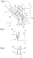
- a first embodiment of the invention is in the FIGS. 1 to 10 partially simplified and schematized.
- the floor cleaning device 1 is shown in the working position of the brush device 20, which occupies this when cleaning a horizontal surface 2. If the substrate 2 is different from the horizontal plane or has unevenness, the brushing device 20 can assume a working position deviating therefrom. In any case, the brushes 5 of the brush device 20 are in contact with the substrate 2 in the respective working positions of the brush device 20.
- the explanations regarding the embodiments of the invention shown in the figures relate, apart from explicit references to other working positions, to that working position of the brush device 20, which occupies these when cleaning a horizontal substrate 2.
- the floor cleaning device 1 has a brush device 20, which is suspended by a suspension unit 10 on a vehicle 4.
- the brush device 20 In one, with respect to the direction of travel 3 of the vehicle 4, the rear area, the brush device 20 has an axle unit 22, which forms a horizontal pivot axis 13 together with the suspension unit 10.
- the brush device 20 is pivotable about the pivot axis 13 and allows a relative angular displacement between the brush device 20 and the suspension unit 10 or the vehicle 4. By pivoting the brush device 20 relative to the suspension unit 10, the brush device 20 can be brought into a passive position, in which brushes 5 are lifted from the ground 2 and are pivoted upwards, so that the brushes 5 are, for example, in a substantially vertical plane.
- the floor cleaning device 1 For swiveling the brush device 20 relative to the suspension unit 10, the floor cleaning device 1 has a lifting element 14 cooperating with the axle unit 22, from which a torque acting about the pivot axis 13 can be exerted on the axle unit 22.
- the lifting member 14 is pivotally connected via the bolt 16 to the lever 24 of the axle unit 22, cf. Fig. 1 and 3 ,
- the lifting member 14 is designed in the embodiment as a piston-cylinder unit and hydraulically connected to a hydraulic unit, not shown, for controlling the movement of the piston-cylinder unit.
- the hydraulic unit can be arranged on the floor cleaning device 1 itself or on the vehicle 4.
- the axle unit 22 has a pivoting tube 29 pivotable about the pivot axis 13 and, in each case, an end face on this connecting part 37 for torsionally rigid connection of the brush housing 30 with the pivot tube 29 of the axle unit 22.
- the axle unit 22 with the pivot axis 13 coaxially aligned guide pin 23.
- Each of these guide pin 23 passes through a thrust member 11 of the suspension unit 10th
- the respective thrust member 11 is integrally formed in the first embodiment of the floor cleaning device 1 with the suspension unit 10 and has a slot 15 in which the guide pins 23 of the axle unit 22 are guided displaceably in the vertical direction.
- the oblong hole 15 delimiting side walls of the pusher member 11 serve to transmit the thrust or the transmission of the movement of the vehicle 4 in the direction of travel 3 on the guide pin 23 of the axle unit 22 of the brush device 20th
- the brush device 20 Due to the mobility of the brush device 20 in the elongated holes 15, the brush device 20 in a, relative to the direction of travel 3, rear portion of the brush device 20 against a force applied by the force member 12 counterforce in the vertical direction relative to the suspension unit 10 can be raised.
- the relative movement of the brush device 20 relative to the suspension unit allows adaptation of the floor cleaning device 1 to uneven surfaces 2, e.g. in step-shaped obstacles, in which a deflection of the brush device 20 upwards relative to the vehicle 4 is necessary to ensure a good cleaning performance.
- the force member 12 acts, favorably directly, with the axle unit 22 of the brush device 20 together and is connected in the exemplary embodiment with an arranged on the pivot tube 29 condyle 25 with the axle unit 22.
- the force member 12 acts, based on the longitudinal extension of the pivot tube 29, centrally on the axle unit 22, see. Fig. 2 ,
- two force elements 12 cooperating laterally with the axle unit 22 could also be provided.
- the counterforce exerted by the force member 12 acts along a vertical line of action which intersects the pivot axis 13.
- the counterforce over the entire possible attachment is constant by the execution of the force member 12 as a piston-cylinder unit.
- the amount of counterforce can also be set as required.
- the piston-cylinder unit is hydraulically connected to a hydraulic unit, not shown, for controlling the movement, which can be arranged on the floor cleaning device 1 itself or on the vehicle 4.
- the friction conditions between the brushes 5 and the surface to be cleaned are different.
- it could come without the force member 12 to raise the rear relative to the direction of travel 3 area of the brush device 20 from the substrate 2.
- the force exerted by the force member 12 counteracting force acts.
- the force with which the front brushes 5 are pressed against the ground 2 is thereby reduced, and the pressure forces of the brushes 5 are divided more evenly.
- the brushes 5 of the brush device 20 which are front-mounted in relation to the direction of travel 3 of the floor cleaning device 1, can be relieved by a torque acting about the pivot axis 13 when cleaning the substrate 2.
- the torque exerted by the lifting member 14 in the sense of relieving the brushes 5 arranged in the front region of the brushing device 10 can be adapted to the friction coefficient of the substrate 2.
- the application of the counterforce by the power member 12 and the exertion of torque by the lifting member 14 allow a largely uniform distribution of Andschreib devise relative to in the direction of travel 3 further forward and further back arranged brushes 5. Since too strong or too lightly loaded brushes 5 the Reduce cleaning performance, can significantly increase the cleaning performance with the force member 12 and the lifting member 14 and a high wear of the front of the brush device 20 arranged brush 5 can be prevented.
- the brush device 20 can be tilted about a parallel to the direction of travel 3 longitudinal axis 7 relative to the suspension unit 10.
- the force member 12 is in this case connected by means of the condyle 25 articulated to the axle unit 22.
- the condyle 25 has for this purpose, for example, a ball joint.
- the force member 12 is favorably hingedly connected to the bolt 16 by means of a ball joint, as is also provided in the embodiment.
- the longitudinal axis 7 is in Fig. 2 drawn as an imaginary or virtual axis. This tiltability allows adaptation of the floor cleaning device 1 to unevenness of the substrate 2 transversely to the direction of travel 3.
- the slots 15 limit the Verkippwinkel the axle unit 22 relative to the suspension unit 10 with respect to the longitudinal axis 7 by a queuing of the respective guide pin 23 at the top or bottom End of the respective slot 15.
- the force member 12 is supported as the lifting member 14 from the suspension unit 10.
- the entire floor cleaning device 1 can therefore be removed as a whole by removing the suspension unit 10 with the brush device 20 from the vehicle 4.
- the attachment of the suspension unit 10 on the vehicle 4 can be realized by well-known, reversibly releasable fastening devices.
- the brush device 20 has in the working position, which occupies this when cleaning a horizontal surface 2, about vertical axes of rotation 6 rotatable brushes 5, which are surrounded by a brush housing 21 open at the bottom.
- a brush housing 21 opens a plurality of steam outlets 35, which are supplied via steam lines 34 with steam generated by a steam generator.
- the steam generator for generating steam is conveniently arranged on the vehicle 4 and connected via corresponding, preferably flexible, lines to the steam lines 34.
- the steam generator could also be part of the floor cleaning device 1.
- the sucked dirt residues are conveniently collected on the vehicle.
- the brush housing 21 on Abdichtschürzen 30, the sealing strips 31 rest in the working position on the substrate 2 and prevent the escape of steam from the brush housing 21 into the environment.
- a suction device 33 of the brush housing 21 for receiving the cleaning liquid or the dissolved from the substrate 2 dirt is arranged.
- the space bounded by the brush housing 21 and the substrate 2 in the working position could also be referred to as the working space of the floor cleaning device 1.
- the respective Abdichtschürzen 30 and arranged in the suction 33 sealing strips 31 are segmented. This ensures an alignment of the sealing strips 31 to the substrate 2 and a reliable seal in uneven floors.
- the sealing strip 31 of the Abdichtschürze is guided in a guide profile 32 in the vertical direction, see. Fig. 4 ,
- the sealing strips 31 of the suction device 33 are shown only schematically, cf. Fig. 5 , These are also displaceable relative to the profile 38 of the suction device 33 in the vertical direction.
- the steam allows the softening of dirt, in particular of chewing gum before the actual mechanical removal by means of the brush 5.
- the water vapor can be in the form of wet steam or dry steam.
- steam outlets 35 hot water outlets which open into the brush housing 21.
- the floor cleaning device 1 has an additional steam apron, which is arranged relative to the direction of travel 3 in front of the brush housing 21 shown in the figures.
- the brush device 20 comprises pressing-brush holder 40, on each of which two of the brushes 5 of the brush device 20 are rotatably mounted about a vertical axis of rotation 6.
- a respective pressing brush holder 40 is pivotable about a horizontal Andschreib brush holder pivot axis 41.
- the Andschreib-brush holder pivot axis 41 is displaceable in the vertical direction relative to the cover part 27 of the brush housing 20 (based on the working position shown in the figures) and acted upon by a pressing force exerted by a pressing unit 44 in the vertical direction, wherein the two brushes 5 to the Underground 2 are pressed.
- the pressing unit 44 is formed by a piston-cylinder unit.
- the contact pressure of the brushes 5 can be conveniently preselected by pre-selection of the hydraulic pressure, wherein the brushes 5 are pressed over the entire stroke of the piston-cylinder unit with a constant contact force against the ground 2. It is conceivable and possible, instead of a piston-cylinder unit to use compression springs or other Anpressussien 44.
- the respective pressing unit 44 is held or supported in an articulated manner on a respective holding part 45, which is attached to the cover part 27 of the brush housing 21.
- the pressing unit 44 is pivotally connected to the Andschreib brush holder 40, see. 8 and 9 ,
- three pressing-brush holders 40 are provided, wherein more or less pressing-brush holder 40 may be provided.
- each support brush holder 50 is pivotable about a horizontal support brush holder pivot axis 51.
- the support brush holder pivot axes 51 are immovable in the vertical direction relative to the cover part 27 of the brush housing 20th held.
- the cover part 27 has guide plates 54 with oblong holes 55 which prevent the movement of the pivot pin 52 forming the supporting brush holder pivot axis 51 in the vertical direction.
- the elongated holes 55 allow a relative movement of the supporting brush holder 50 relative to the cover part 27 of the brush housing 21 in the horizontal direction in or against the direction of travel 3.
- the slot 55 has in the figures a much greater longitudinal extent in the direction of travel 3, as to the functionality of the ground -Cleaning device 1 is necessary.
- the representation serves only for a better representation of the function.
- Both the pressing brush holder 40, and the support brush holder 50 pass through two guide bottle 28 of the lid part 27, which limit the movement of the pressing brush holder 40 and the support brush holder 50 in the horizontal direction, see. Fig. 6 and Fig. 8 , Between the guide flange 28 and the pressing brush holder 40 and the support brush holder 50, a game is provided to allow pivoting about the Andschreib brush holder pivot axis 41 and the support brush holder pivot axis 51, without causing any Verzwnature , This is not shown separately in the figures.
- the brushes 5 are held immovably in the vertical direction with respect to the pressing brush holder 40 and the supporting brush holder 50.
- the brushes 5 in the working position of the brush device it is conceivable and possible for the brushes 5 in the working position of the brush device to be displaceable in the vertical direction relative to the pressing brush holder and / or the supporting brush holder against a spring force exerted by a compression spring.
- a deflection of one of the two brushes 5 respectively held on the pressing brush holder 40 and on the supporting brush holder 50 in a vertical upward direction leads to a deflection of the other brush 5 in the opposite direction, by pivoting the pressing brush holder 40 or the supporting brush holder 5.
- the Andschreib brush holder 40 and the support brush holder 50th thus act similar to a rocker, wherein the pressure forces of the respective brushes 5 are divided due to the geometric design.
- the supporting brush holder pivot axis 51 of the supporting brush holder 50 and the pressing brush holder pivot axis 41 of the pressing brush holder 40 are therefore eccentrically arranged between the two brushes 5 supported on the supporting brush holder 50 and the pressing brush holder 40 in the exemplary embodiment. Due to the off-center arrangement of the pivot axes, a uniform distribution of the contact pressure on the brushes 5 arranged on the respective supporting brush holder 50 or pressing brush holder 40 is achieved.
- the pressing brush holders 40 are arranged in the region between the supporting brush holders 50.
- This is particularly advantageous for small-scale uneven floors, since a uniform cleaning performance of the floor cleaning device 1 can be achieved at all points of the substrate 2 by all brushes 5 of the brush holder 20 fit snugly on the substrate 2.
- the pressing force can be adjusted accordingly.
- the supporting brush holder pivot axes 51 of the support brush holder 50 and the pressing brush holder pivot axes 41 of the pressing brush holder 40 are aligned parallel to each other and orthogonal to the direction of travel 3.
- the pressing-brush holder pivot axes 41 and the support brush holder pivot axes 51 each juxtaposed pressing-brush holder 40 and / or support brush holder 50 are arranged offset in the embodiment with respect to the direction of travel 3 to each other.
- the juxtaposed pressing brush holder 40 and / or supporting brush holder 50 are arranged overlapping with respect to the direction of travel 3. This makes it possible to nest the brushes 5, which are juxtaposed with respect to one direction orthogonal to the direction of travel 3, and thus overlap the areas swept by the brushes 5 when the brush device 20 moves in the direction of travel 3.
- Each of the brushes 5 is individually rotatable in the exemplary embodiment by means of a respective motor 36 about a vertical axis of rotation. This is an individual driving the brush 5, z. B. possible with different rotational speeds or in different directions. By the opposite direction of rotation, for example, based on the direction of travel 3 consecutively arranged brushes 5, the cleaning performance can be further increased. It is also conceivable and possible, for example, for the two brushes 5 mounted on a pressing brush holder 40 or on the supporting brush holder 50 to be driven by a common motor 36 and a corresponding distributor gear.
- Fig. 11 to 13 illustrated second embodiment of a floor cleaning device 1 according to the invention differs from the first embodiment in terms of the type of suspension of the brush device 20 on the suspension unit 10 and the initiation of the thrust forces to move the brush device. Apart from the still to be explained below Differences from the first embodiment corresponds to the embodiment of that of the first embodiment and reference is made to the description of the figures for the first embodiment.
- the axle unit 22 is movable in the second embodiment both in the vertical and in the horizontal direction relative to the suspension unit 10.
- the guide pins 23 pass through a window recess 17 of the suspension unit 10, cf. Fig. 11 to 13 ,
- the push members 11 of the suspension unit 10 are formed here as separate parts and act in the working position, the brush device 20 for movement in the direction of travel 3 directed against the direction of travel 3 surfaces 26 of the brush device 20.
- the thrust members 11 are disposed below the height of the pivot axis 13. In contrast to the first embodiment, the suspension unit 10 thus does not interact with the axle unit 22 to transmit the thrust.
- the thrust members 11 are conveniently adjustable in height relative to the thrust member 11 supporting part of the suspension unit 10. This is not shown separately in the figures. In particular, due to the different soil conditions or friction coefficients of the substrate 2 and the frictional forces acting thereby can be equalized by a height adjustment, the torque acting through the friction about the pivot axis 13. By a corresponding arrangement of the thrust member 11 at a certain height, depending on the friction conditions occurring a corresponding counter-torque can be adjusted. In this case, the force member 14 can be conveniently unlocked, d. H. that in the working position no additional torque from the lifting unit 10 to the axle unit 22 about the pivot axis 13 must be exercised. However, it is also conceivable and possible, even in the second embodiment, to use the lifting unit 14 for exerting a torque about the pivot axis 13.
- both guide pins 23 are on a window recess 17 upwardly bounding wall, see. Fig. 13 .
- the Force member 12 may in this case, in contrast to the working position, be controlled so that it moves into a retracted position and the axle unit 22 holds above.
- the guide pin 23 in the working position of the brush device 20, which occupies this when cleaning a horizontal surface 2, seen in the vertical direction is arranged centrally between the limiting walls of the recess 17 of the suspension unit 10.
- the thrust member 11 allows in the second embodiment, an adjustment of the position of the brush device 20 relative to the vehicle 4 seen in the direction of travel 3, by the variation of the length of the thrust member 11, which is shown in the embodiment as an adjusting screw.
- the lifting member 14 is supported at a different location on the vehicle than on the suspension unit 10.
- the force member 12 is supported at a different point of the vehicle on the vehicle. It is of course conceivable and possible for the lifting member 14 and the force member 12 to be supported on the suspension unit 10 analogously to the first exemplary embodiment.
- the drawn in the figures direction 3 refers to a straight ahead of the vehicle 4. Other directions, eg when driving on bends are possible. Also, a reverse drive against the marked direction of travel 3 is conveniently at least at a slow pace possible, possibly with reduced cleaning performance.
- the thrust force in a reverse drive in the region of the axle unit 22 must be initiated.
Landscapes
- Vehicle Cleaning, Maintenance, Repair, Refitting, And Outriggers (AREA)
Claims (14)
- Dispositif de nettoyage du sol (1), comprenant un dispositif à brosses (20), lequel comporte des brosses (5) pouvant tourner autour d'axes de rotation verticaux (6) par rapport à une position de travail du dispositif à brosses (20) que celui-ci occupe lors du nettoyage d'un sol horizontal (6), et un logement de brosses (21) ouvert vers le bas et entourant au moins en parties les brosses (5), logement dans lequel débouche au moins une sortie de vapeur (35) pour la vapeur produite par un générateur de vapeur et/ou au moins une sortie d'eau chaude, le dispositif à brosses (20), dans la position de travail, étant soumis à l'effet d'une force de poussée exercée par au moins une unité de suspension (10) du dispositif de nettoyage du sol (1) par l'intermédiaire de laquelle le dispositif de nettoyage du sol (1) peut être fixé à un véhicule (4), en vue de déplacer le dispositif à brosses (20) dans un sens de la marche, au moins un organe applicateur de force (12) du dispositif de nettoyage du sol (1) coopérant avec le dispositif à brosses (20), et le dispositif à brosses (20), dans une zone arrière du dispositif à brosses (20) par rapport au sens de la marche (3), pouvant être soulevé par rapport à l'unité ou aux unités de suspension (10) à l'encontre d'une force antagoniste exercée par au moins un organe applicateur de force (12) dans le sens vertical, caractérisé en ce que, par rapport à la position de travail du dispositif à brosses (20) que celui-ci occupe lors du nettoyage d'un sol horizontal (2), au moins une des brosses (5) du dispositif à brosses (20) peut être déplacée en direction verticale par rapport à une partie de couvercle (27) du logement de brosses (21), et la brosse (5) est appuyée sur le sol (2) par une force de pression exercée par une unité de pression (44), ou au moins un porte-brosses d'appui (40) du dispositif à brosses (20) est présent, sur lequel au moins deux des brosses (5) du dispositif à brosses (20) sont montées rotatives chacune autour d'un axe de rotation vertical (6), et qui peut pivoter autour d'un axe de pivotement (41) de porte-brosses d'appui horizontal, lequel axe peut coulisser en direction verticale par rapport à la partie de couvercle (27) du logement de brosses (21) et qui est soumis à l'effet d'une force de pression exercée par une unité de pression (44) en direction verticale, les au moins deux brosses (5) étant alors appuyées sur le sol (2).
- Dispositif de nettoyage du sol (1) selon la revendication 1, caractérisé en ce que le dispositif à brosses (20) comprend, dans une zone arrière par rapport au sens de la marche (3), une unité d'axe (22) qui forme conjointement avec l'au moins une unité de suspension (10) un axe de pivotement (13) horizontal dans la position de travail du dispositif à brosses (20) que celui-ci occupe lors du nettoyage d'un sol horizontal (2), le dispositif à brosses (20) pouvant pivoter autour de l'axe de pivotement, l'axe de pivotement (13) étant mobile au moins en direction verticale.
- Dispositif de nettoyage du sol (1) selon la revendication 2, caractérisé en ce que l'organe applicateur de force (12) coopère avec l'unité d'axe (22).
- Dispositif de nettoyage du sol (1) selon la revendication 2 ou 3, caractérisé en ce que l'unité d'axe (22) est guidée de façon coulissante en direction verticale par l'unité de suspension (10) et en ce que l'unité de suspension (10), dans la position de travail du dispositif à brosses (20), soumet l'unité d'axe (22) du dispositif à brosses (20) à la force de poussée pour le déplacement du dispositif à brosses (20) dans le sens de la marche (3).
- Dispositif de nettoyage du sol (1) selon la revendication 2 ou 3, caractérisé en ce que l'unité d'axe (22) est mobile en direction horizontale par rapport à l'unité de suspension (10), et l'unité de suspension (10), dans la position de travail du dispositif à brosses (20), soumet le dispositif à brosses (20) en dessous de la hauteur de l'axe de pivotement (13), sur une surface (26) du dispositif à brosses (20) orientée dans le sens opposé au sens de la marche (3), à la force de poussée pour le déplacement du dispositif à brosses (20) dans le sens de la marche (3), la force de poussée étant transmise au dispositif à brosses (20) par au moins un organe de poussée (11) de l'unité de suspension (10).
- Dispositif de nettoyage du sol (1) selon la revendication 5, caractérisé en ce que l'organe de poussée (11) peut être réglé en hauteur par rapport à une partie de l'unité de suspension (10) portant l'organe de poussée (11).
- Dispositif de nettoyage du sol (1) selon l'une des revendications 2 à 6, caractérisé en ce que le dispositif de nettoyage du sol (1) comprend au moins un organe de relevage (14) qui coopère avec l'unité d'axe (22) et par lequel un couple agissant sur l'axe de pivotement (13) peut être exercé sur l'unité d'axe (22).
- Dispositif de nettoyage du sol (1) selon l'une des revendications 1 à 7, caractérisé en ce que, par rapport à la position de travail du dispositif à brosses (20) que celui-ci occupe lors du nettoyage d'un sol horizontal (2), au moins une des brosses (5) du dispositif à brosses (20) est retenue immobile dans le sens vertical par rapport à la partie de couvercle (27) du logement de brosses (21), ou le dispositif à brosses (20) comprend au moins un porte-brosses support (50) sur lequel au moins deux des brosses (5) du dispositif à brosses (20) sont montées rotatives autour d'axes de rotation verticaux (6) et qui peut pivoter autour d'un axe de pivotement de porte-brosses support (51) horizontal qui est retenu immobile en direction verticale par rapport à la partie de couvercle (27) du logement de brosses (21).
- Dispositif de nettoyage du sol (1) selon l'une des revendications 1 à 8, caractérisé en ce que les brosses (5) montées sur le porte-brosses d'appui (40) en étant rotatives autour d'un axe de rotation vertical (6) sont retenues immobiles en direction verticale par rapport au porte-brosses d'appui (40) et/ou en ce que les brosses (5) montées sur le porte-brosses support (50) en étant rotatives autour d'un axe de rotation vertical (6) sont retenues immobiles en direction verticale par rapport au porte-brosses support (50).
- Dispositif de nettoyage du sol (1) selon l'une des revendications 8 ou 9, caractérisé en ce que le dispositif à brosses (20) comprend deux porte-brosses support (50) et au moins deux porte-brosses d'appui (40) qui sont agencés dans la zone située entre les porte-brosses support (50), et les axes de pivotement des porte-brosses support (51) des porte-brosses support (50) et les axes de pivotement des porte-brosses d'appui (41) des porte-brosses d'appui (40) sont orientés parallèlement les uns aux autres.
- Dispositif de nettoyage du sol (1) selon l'une des revendications 1 à 10, caractérisé en ce que l'axe de pivotement de porte-brosses support (51) respectif du porte-brosses support (50) et/ou l'axe de pivotement du porte-brosses d'appui (41) respectif du porte-brosses d'appui (40) sont disposés de façon excentrée entre deux brosses (5) montées rotatives autour de l'axe de rotation vertical (6) respectivement sur le porte-brosses support (50) et/ou sur le porte-brosses d'appui (40).
- Dispositif de nettoyage du sol (1) selon l'une des revendications 1 à 11, caractérisé en ce que les brosses (5), pour tourner autour d'un axe de rotation vertical (6), sont entraînées chacune séparément par un moteur (36) respectif, ou au moins deux brosses (5) disposées sur un porte-brosses d'appui (40) et/ou sur un porte-brosses support (50) sont entraînées conjointement par un moteur (36).
- Dispositif de nettoyage du sol (1) selon l'une des revendications 1 à 12, caractérisé en ce que le dispositif à brosses (20) comprend un dispositif d'aspiration (33) pour aspirer la saleté retirée du sol (2), lequel est disposé, par rapport au sens de la marche (3), dans la zone arrière du dispositif à brosses (20).
- Dispositif de nettoyage du sol (1) selon l'une des revendications 1 à 13, caractérisé en ce que l'organe applicateur de force (12) est une unité à piston-cylindre.
Priority Applications (1)
| Application Number | Priority Date | Filing Date | Title |
|---|---|---|---|
| PL16165923T PL3092932T3 (pl) | 2015-05-15 | 2016-04-19 | Urządzenie do czyszczenia podłogi |
Applications Claiming Priority (1)
| Application Number | Priority Date | Filing Date | Title |
|---|---|---|---|
| ATA307/2015A AT516710B1 (de) | 2015-05-15 | 2015-05-15 | Boden-Reinigungseinrichtung |
Publications (2)
| Publication Number | Publication Date |
|---|---|
| EP3092932A1 EP3092932A1 (fr) | 2016-11-16 |
| EP3092932B1 true EP3092932B1 (fr) | 2017-09-27 |
Family
ID=55794869
Family Applications (1)
| Application Number | Title | Priority Date | Filing Date |
|---|---|---|---|
| EP16165923.0A Active EP3092932B1 (fr) | 2015-05-15 | 2016-04-19 | Dispositif de nettoyage du sol |
Country Status (5)
| Country | Link |
|---|---|
| EP (1) | EP3092932B1 (fr) |
| AT (1) | AT516710B1 (fr) |
| ES (1) | ES2652563T3 (fr) |
| HU (1) | HUE037609T2 (fr) |
| PL (1) | PL3092932T3 (fr) |
Cited By (1)
| Publication number | Priority date | Publication date | Assignee | Title |
|---|---|---|---|---|
| WO2026032999A1 (fr) * | 2024-08-06 | 2026-02-12 | Nilfisk A/S | Mécanisme de levage de raclette activé par actionneur |
Families Citing this family (6)
| Publication number | Priority date | Publication date | Assignee | Title |
|---|---|---|---|---|
| DE102017002948B4 (de) * | 2017-03-24 | 2019-09-19 | Viarius Gmbh | Bodenreinigungsmaschine mit heb- und senkbarem Reinigungsmodul und Verfahren zum Betrieb |
| CZ31974U1 (cs) | 2018-06-12 | 2018-08-14 | GETURA PLUS, spol. s r.o. | Stacionární zařízení pro automatické čištění podlah místností |
| CN108606738A (zh) * | 2018-07-06 | 2018-10-02 | 苏州宏奇锐自动化有限公司 | 一种地面清洁机器人的清洁机构 |
| CN112956956A (zh) * | 2021-02-18 | 2021-06-15 | 美智纵横科技有限责任公司 | 清洁系统、控制方法、计算机设备及计算机可读存储介质 |
| CN112914431B (zh) * | 2021-03-25 | 2022-06-21 | 云鲸智能科技(东莞)有限公司 | 清洁组件及清洁机器人 |
| CN112890701A (zh) * | 2021-04-21 | 2021-06-04 | 广东美房智高机器人有限公司 | 一种吸水扒调节装置及洗地机 |
Family Cites Families (8)
| Publication number | Priority date | Publication date | Assignee | Title |
|---|---|---|---|---|
| GB8907481D0 (en) * | 1989-04-03 | 1989-05-17 | Unilever Plc | Floor-cleaning machine |
| US5922968A (en) * | 1995-09-06 | 1999-07-13 | Briscoe; William Anthony | Brush pressure system |
| WO2002094075A2 (fr) * | 2001-05-21 | 2002-11-28 | Tennant Company | Dispositif de suspension pour appareil d'entretien des sols |
| GB0410255D0 (en) * | 2004-05-07 | 2004-06-09 | Briscoe William A | Surface working apparatus |
| JP5898308B2 (ja) * | 2011-06-17 | 2016-04-06 | アルフレット ケルヒャー ゲゼルシャフト ミット ベシュレンクテル ハフツング ウント コンパニー コマンディトゲゼルシャフト | 清掃車 |
| CN103717117A (zh) * | 2011-08-02 | 2014-04-09 | 阿尔弗雷德·凯驰两合公司 | 可行驶的地板清洁机和用于操作地板清洁机的方法 |
| JP5986230B2 (ja) * | 2012-02-16 | 2016-09-06 | テンナント カンパニー | 小型のクリーニングヘッドリフト機構およびサスペンションを有する表面メンテナンス車 |
| US9498099B2 (en) * | 2012-02-16 | 2016-11-22 | Tennant Company | Surface maintenance vehicle with compact side brush assembly |
-
2015
- 2015-05-15 AT ATA307/2015A patent/AT516710B1/de not_active IP Right Cessation
-
2016
- 2016-04-19 ES ES16165923.0T patent/ES2652563T3/es active Active
- 2016-04-19 EP EP16165923.0A patent/EP3092932B1/fr active Active
- 2016-04-19 PL PL16165923T patent/PL3092932T3/pl unknown
- 2016-04-19 HU HUE16165923A patent/HUE037609T2/hu unknown
Non-Patent Citations (1)
| Title |
|---|
| None * |
Cited By (1)
| Publication number | Priority date | Publication date | Assignee | Title |
|---|---|---|---|---|
| WO2026032999A1 (fr) * | 2024-08-06 | 2026-02-12 | Nilfisk A/S | Mécanisme de levage de raclette activé par actionneur |
Also Published As
| Publication number | Publication date |
|---|---|
| HUE037609T2 (hu) | 2018-09-28 |
| AT516710A4 (de) | 2016-08-15 |
| EP3092932A1 (fr) | 2016-11-16 |
| PL3092932T3 (pl) | 2018-03-30 |
| AT516710B1 (de) | 2016-08-15 |
| ES2652563T3 (es) | 2018-02-05 |
Similar Documents
| Publication | Publication Date | Title |
|---|---|---|
| EP3092932B1 (fr) | Dispositif de nettoyage du sol | |
| EP0580186B1 (fr) | Machine de nettoyage du sol | |
| EP2470055B1 (fr) | Appareil de traitement de sol à guidage manuel | |
| EP1704283B1 (fr) | Machine automotrice servant a realiser des voies de circulation | |
| EP2721220A1 (fr) | Balayeuse de voirie comprenant un dispositif de réglage de disque de brosse | |
| EP2954817A1 (fr) | Machine de nettoyage du sol | |
| DE2345639A1 (de) | Staubsauger | |
| CH665524A5 (de) | Kreiselegge zur saatbettbereitung. | |
| DE10221351B4 (de) | Bodenreinigungsmaschine | |
| EP3998926A1 (fr) | Machine de nettoyage de sols | |
| EP3417756B1 (fr) | Machine de nettoyage du sol dotée d'un réglage d'appui de brosse | |
| DE2818717A1 (de) | Schleppergezogener, fahrbarer rahmen fuer bodenbearbeitungswerkzeuge bzw. -geraete | |
| EP3415067A1 (fr) | Dispositif formant balai latéral pour une machine de nettoyage du sol | |
| EP1816265A1 (fr) | Balayeuse pour nettoyer des voies, des routes ou surfaces utilisables similaires | |
| EP3403562B1 (fr) | Dispositif de ventouse pour une machine de nettoyage de sol et machine de nettoyage de sol | |
| DE102012103905B4 (de) | Reinigungsvorrichtung für Photovoltaik-Module und Trägerfahrzeug dafür | |
| DE9115713U1 (de) | Scheuersaugmaschine | |
| EP3586970B1 (fr) | Concasseur à mâchoires | |
| DE2649442C2 (de) | Bodenbearbeitungsmaschine | |
| DE4140641C2 (fr) | ||
| EP1529427B1 (fr) | Machine agricole à travail du sol et/ou de semis | |
| EP3013205A1 (fr) | Machine de nettoyage de sol autoportée mobile et procédé de positionnement d'une rampe aspirante d'une machine de nettoyage de sol autoportée mobile | |
| DE69910904T2 (de) | Sähmaschine | |
| DE69421954T2 (de) | Landwirtschaftliche Bodenbearbeitungsmaschine mit grosser Breite, die sich besser an die Bodenunebenheit anpasst | |
| WO2015155269A1 (fr) | Procédé pour faire fonctionner une machine de nettoyage de sol et machine de nettoyage de sol |
Legal Events
| Date | Code | Title | Description |
|---|---|---|---|
| PUAI | Public reference made under article 153(3) epc to a published international application that has entered the european phase |
Free format text: ORIGINAL CODE: 0009012 |
|
| AK | Designated contracting states |
Kind code of ref document: A1 Designated state(s): AL AT BE BG CH CY CZ DE DK EE ES FI FR GB GR HR HU IE IS IT LI LT LU LV MC MK MT NL NO PL PT RO RS SE SI SK SM TR |
|
| AX | Request for extension of the european patent |
Extension state: BA ME |
|
| 17P | Request for examination filed |
Effective date: 20170508 |
|
| RBV | Designated contracting states (corrected) |
Designated state(s): AL AT BE BG CH CY CZ DE DK EE ES FI FR GB GR HR HU IE IS IT LI LT LU LV MC MK MT NL NO PL PT RO RS SE SI SK SM TR |
|
| GRAP | Despatch of communication of intention to grant a patent |
Free format text: ORIGINAL CODE: EPIDOSNIGR1 |
|
| INTG | Intention to grant announced |
Effective date: 20170620 |
|
| GRAS | Grant fee paid |
Free format text: ORIGINAL CODE: EPIDOSNIGR3 |
|
| GRAA | (expected) grant |
Free format text: ORIGINAL CODE: 0009210 |
|
| AK | Designated contracting states |
Kind code of ref document: B1 Designated state(s): AL AT BE BG CH CY CZ DE DK EE ES FI FR GB GR HR HU IE IS IT LI LT LU LV MC MK MT NL NO PL PT RO RS SE SI SK SM TR |
|
| REG | Reference to a national code |
Ref country code: GB Ref legal event code: FG4D Free format text: NOT ENGLISH |
|
| REG | Reference to a national code |
Ref country code: CH Ref legal event code: EP |
|
| REG | Reference to a national code |
Ref country code: AT Ref legal event code: REF Ref document number: 931199 Country of ref document: AT Kind code of ref document: T Effective date: 20171015 |
|
| REG | Reference to a national code |
Ref country code: IE Ref legal event code: FG4D Free format text: LANGUAGE OF EP DOCUMENT: GERMAN |
|
| REG | Reference to a national code |
Ref country code: DE Ref legal event code: R096 Ref document number: 502016000166 Country of ref document: DE |
|
| REG | Reference to a national code |
Ref country code: CH Ref legal event code: NV Representative=s name: LUCHS AND PARTNER AG PATENTANWAELTE, CH |
|
| REG | Reference to a national code |
Ref country code: NL Ref legal event code: FP |
|
| REG | Reference to a national code |
Ref country code: SE Ref legal event code: TRGR |
|
| PG25 | Lapsed in a contracting state [announced via postgrant information from national office to epo] |
Ref country code: HR Free format text: LAPSE BECAUSE OF FAILURE TO SUBMIT A TRANSLATION OF THE DESCRIPTION OR TO PAY THE FEE WITHIN THE PRESCRIBED TIME-LIMIT Effective date: 20170927 Ref country code: LT Free format text: LAPSE BECAUSE OF FAILURE TO SUBMIT A TRANSLATION OF THE DESCRIPTION OR TO PAY THE FEE WITHIN THE PRESCRIBED TIME-LIMIT Effective date: 20170927 Ref country code: FI Free format text: LAPSE BECAUSE OF FAILURE TO SUBMIT A TRANSLATION OF THE DESCRIPTION OR TO PAY THE FEE WITHIN THE PRESCRIBED TIME-LIMIT Effective date: 20170927 Ref country code: NO Free format text: LAPSE BECAUSE OF FAILURE TO SUBMIT A TRANSLATION OF THE DESCRIPTION OR TO PAY THE FEE WITHIN THE PRESCRIBED TIME-LIMIT Effective date: 20171227 |
|
| REG | Reference to a national code |
Ref country code: ES Ref legal event code: FG2A Ref document number: 2652563 Country of ref document: ES Kind code of ref document: T3 Effective date: 20180205 |
|
| REG | Reference to a national code |
Ref country code: LT Ref legal event code: MG4D |
|
| PG25 | Lapsed in a contracting state [announced via postgrant information from national office to epo] |
Ref country code: GR Free format text: LAPSE BECAUSE OF FAILURE TO SUBMIT A TRANSLATION OF THE DESCRIPTION OR TO PAY THE FEE WITHIN THE PRESCRIBED TIME-LIMIT Effective date: 20171228 Ref country code: LV Free format text: LAPSE BECAUSE OF FAILURE TO SUBMIT A TRANSLATION OF THE DESCRIPTION OR TO PAY THE FEE WITHIN THE PRESCRIBED TIME-LIMIT Effective date: 20170927 Ref country code: BG Free format text: LAPSE BECAUSE OF FAILURE TO SUBMIT A TRANSLATION OF THE DESCRIPTION OR TO PAY THE FEE WITHIN THE PRESCRIBED TIME-LIMIT Effective date: 20171227 Ref country code: RS Free format text: LAPSE BECAUSE OF FAILURE TO SUBMIT A TRANSLATION OF THE DESCRIPTION OR TO PAY THE FEE WITHIN THE PRESCRIBED TIME-LIMIT Effective date: 20170927 |
|
| REG | Reference to a national code |
Ref country code: SK Ref legal event code: T3 Ref document number: E 26037 Country of ref document: SK |
|
| REG | Reference to a national code |
Ref country code: FR Ref legal event code: PLFP Year of fee payment: 3 |
|
| PG25 | Lapsed in a contracting state [announced via postgrant information from national office to epo] |
Ref country code: EE Free format text: LAPSE BECAUSE OF FAILURE TO SUBMIT A TRANSLATION OF THE DESCRIPTION OR TO PAY THE FEE WITHIN THE PRESCRIBED TIME-LIMIT Effective date: 20170927 Ref country code: IS Free format text: LAPSE BECAUSE OF FAILURE TO SUBMIT A TRANSLATION OF THE DESCRIPTION OR TO PAY THE FEE WITHIN THE PRESCRIBED TIME-LIMIT Effective date: 20180127 Ref country code: SM Free format text: LAPSE BECAUSE OF FAILURE TO SUBMIT A TRANSLATION OF THE DESCRIPTION OR TO PAY THE FEE WITHIN THE PRESCRIBED TIME-LIMIT Effective date: 20170927 |
|
| REG | Reference to a national code |
Ref country code: DE Ref legal event code: R097 Ref document number: 502016000166 Country of ref document: DE |
|
| PG25 | Lapsed in a contracting state [announced via postgrant information from national office to epo] |
Ref country code: DK Free format text: LAPSE BECAUSE OF FAILURE TO SUBMIT A TRANSLATION OF THE DESCRIPTION OR TO PAY THE FEE WITHIN THE PRESCRIBED TIME-LIMIT Effective date: 20170927 |
|
| PLBE | No opposition filed within time limit |
Free format text: ORIGINAL CODE: 0009261 |
|
| STAA | Information on the status of an ep patent application or granted ep patent |
Free format text: STATUS: NO OPPOSITION FILED WITHIN TIME LIMIT |
|
| 26N | No opposition filed |
Effective date: 20180628 |
|
| PG25 | Lapsed in a contracting state [announced via postgrant information from national office to epo] |
Ref country code: MT Free format text: LAPSE BECAUSE OF FAILURE TO SUBMIT A TRANSLATION OF THE DESCRIPTION OR TO PAY THE FEE WITHIN THE PRESCRIBED TIME-LIMIT Effective date: 20170927 |
|
| REG | Reference to a national code |
Ref country code: HU Ref legal event code: AG4A Ref document number: E037609 Country of ref document: HU |
|
| PG25 | Lapsed in a contracting state [announced via postgrant information from national office to epo] |
Ref country code: SI Free format text: LAPSE BECAUSE OF FAILURE TO SUBMIT A TRANSLATION OF THE DESCRIPTION OR TO PAY THE FEE WITHIN THE PRESCRIBED TIME-LIMIT Effective date: 20170927 |
|
| REG | Reference to a national code |
Ref country code: IE Ref legal event code: MM4A |
|
| PG25 | Lapsed in a contracting state [announced via postgrant information from national office to epo] |
Ref country code: IE Free format text: LAPSE BECAUSE OF NON-PAYMENT OF DUE FEES Effective date: 20180419 |
|
| PG25 | Lapsed in a contracting state [announced via postgrant information from national office to epo] |
Ref country code: TR Free format text: LAPSE BECAUSE OF FAILURE TO SUBMIT A TRANSLATION OF THE DESCRIPTION OR TO PAY THE FEE WITHIN THE PRESCRIBED TIME-LIMIT Effective date: 20170927 |
|
| PG25 | Lapsed in a contracting state [announced via postgrant information from national office to epo] |
Ref country code: PT Free format text: LAPSE BECAUSE OF FAILURE TO SUBMIT A TRANSLATION OF THE DESCRIPTION OR TO PAY THE FEE WITHIN THE PRESCRIBED TIME-LIMIT Effective date: 20170927 |
|
| PG25 | Lapsed in a contracting state [announced via postgrant information from national office to epo] |
Ref country code: CY Free format text: LAPSE BECAUSE OF FAILURE TO SUBMIT A TRANSLATION OF THE DESCRIPTION OR TO PAY THE FEE WITHIN THE PRESCRIBED TIME-LIMIT Effective date: 20170927 Ref country code: RO Free format text: LAPSE BECAUSE OF FAILURE TO SUBMIT A TRANSLATION OF THE DESCRIPTION OR TO PAY THE FEE WITHIN THE PRESCRIBED TIME-LIMIT Effective date: 20170927 Ref country code: MK Free format text: LAPSE BECAUSE OF NON-PAYMENT OF DUE FEES Effective date: 20170927 |
|
| PG25 | Lapsed in a contracting state [announced via postgrant information from national office to epo] |
Ref country code: AL Free format text: LAPSE BECAUSE OF FAILURE TO SUBMIT A TRANSLATION OF THE DESCRIPTION OR TO PAY THE FEE WITHIN THE PRESCRIBED TIME-LIMIT Effective date: 20170927 |
|
| PGFP | Annual fee paid to national office [announced via postgrant information from national office to epo] |
Ref country code: PL Payment date: 20210329 Year of fee payment: 6 |
|
| PGFP | Annual fee paid to national office [announced via postgrant information from national office to epo] |
Ref country code: LU Payment date: 20210426 Year of fee payment: 6 Ref country code: SK Payment date: 20210330 Year of fee payment: 6 |
|
| PGFP | Annual fee paid to national office [announced via postgrant information from national office to epo] |
Ref country code: MC Payment date: 20210421 Year of fee payment: 6 Ref country code: CZ Payment date: 20210419 Year of fee payment: 6 |
|
| PGFP | Annual fee paid to national office [announced via postgrant information from national office to epo] |
Ref country code: HU Payment date: 20210330 Year of fee payment: 6 Ref country code: SE Payment date: 20210422 Year of fee payment: 6 Ref country code: BE Payment date: 20210426 Year of fee payment: 6 |
|
| REG | Reference to a national code |
Ref country code: DE Ref legal event code: R081 Ref document number: 502016000166 Country of ref document: DE Owner name: KECKEX GMBH, AT Free format text: FORMER OWNER: K + S GMBH, LAUTERACH, AT |
|
| REG | Reference to a national code |
Ref country code: GB Ref legal event code: 732E Free format text: REGISTERED BETWEEN 20211111 AND 20211117 |
|
| REG | Reference to a national code |
Ref country code: NL Ref legal event code: PD Owner name: KECKEX GMBH; AT Free format text: DETAILS ASSIGNMENT: CHANGE OF OWNER(S), ASSIGNMENT; FORMER OWNER NAME: K + S GMBH Effective date: 20211123 |
|
| REG | Reference to a national code |
Ref country code: ES Ref legal event code: PC2A Owner name: KECKEX GMBH Effective date: 20211230 |
|
| REG | Reference to a national code |
Ref country code: AT Ref legal event code: PC Ref document number: 931199 Country of ref document: AT Kind code of ref document: T Owner name: KECKEX GMBH, AT Effective date: 20220107 |
|
| REG | Reference to a national code |
Ref country code: SE Ref legal event code: EUG |
|
| REG | Reference to a national code |
Ref country code: SK Ref legal event code: MM4A Ref document number: E 26037 Country of ref document: SK Effective date: 20220419 |
|
| REG | Reference to a national code |
Ref country code: BE Ref legal event code: MM Effective date: 20220430 |
|
| PG25 | Lapsed in a contracting state [announced via postgrant information from national office to epo] |
Ref country code: SK Free format text: LAPSE BECAUSE OF NON-PAYMENT OF DUE FEES Effective date: 20220419 Ref country code: SE Free format text: LAPSE BECAUSE OF NON-PAYMENT OF DUE FEES Effective date: 20220420 Ref country code: MC Free format text: LAPSE BECAUSE OF NON-PAYMENT OF DUE FEES Effective date: 20220502 Ref country code: LU Free format text: LAPSE BECAUSE OF NON-PAYMENT OF DUE FEES Effective date: 20220419 Ref country code: HU Free format text: LAPSE BECAUSE OF NON-PAYMENT OF DUE FEES Effective date: 20220420 Ref country code: CZ Free format text: LAPSE BECAUSE OF NON-PAYMENT OF DUE FEES Effective date: 20220419 |
|
| PG25 | Lapsed in a contracting state [announced via postgrant information from national office to epo] |
Ref country code: BE Free format text: LAPSE BECAUSE OF NON-PAYMENT OF DUE FEES Effective date: 20220430 |
|
| PG25 | Lapsed in a contracting state [announced via postgrant information from national office to epo] |
Ref country code: PL Free format text: LAPSE BECAUSE OF NON-PAYMENT OF DUE FEES Effective date: 20220419 |
|
| PGFP | Annual fee paid to national office [announced via postgrant information from national office to epo] |
Ref country code: NL Payment date: 20250424 Year of fee payment: 10 |
|
| PGFP | Annual fee paid to national office [announced via postgrant information from national office to epo] |
Ref country code: DE Payment date: 20250428 Year of fee payment: 10 |
|
| PGFP | Annual fee paid to national office [announced via postgrant information from national office to epo] |
Ref country code: ES Payment date: 20250513 Year of fee payment: 10 |
|
| PGFP | Annual fee paid to national office [announced via postgrant information from national office to epo] |
Ref country code: IT Payment date: 20250422 Year of fee payment: 10 |
|
| PGFP | Annual fee paid to national office [announced via postgrant information from national office to epo] |
Ref country code: FR Payment date: 20250424 Year of fee payment: 10 |
|
| PGFP | Annual fee paid to national office [announced via postgrant information from national office to epo] |
Ref country code: CH Payment date: 20250501 Year of fee payment: 10 |
|
| PGFP | Annual fee paid to national office [announced via postgrant information from national office to epo] |
Ref country code: AT Payment date: 20250410 Year of fee payment: 10 |
|
| PGFP | Annual fee paid to national office [announced via postgrant information from national office to epo] |
Ref country code: GB Payment date: 20260325 Year of fee payment: 11 |