EP0580307A1 - Dispositif de filtrage à ondes acoustiques de surface - Google Patents
Dispositif de filtrage à ondes acoustiques de surface Download PDFInfo
- Publication number
- EP0580307A1 EP0580307A1 EP93305195A EP93305195A EP0580307A1 EP 0580307 A1 EP0580307 A1 EP 0580307A1 EP 93305195 A EP93305195 A EP 93305195A EP 93305195 A EP93305195 A EP 93305195A EP 0580307 A1 EP0580307 A1 EP 0580307A1
- Authority
- EP
- European Patent Office
- Prior art keywords
- electrode
- fingers
- acoustic wave
- surface acoustic
- finger
- Prior art date
- Legal status (The legal status is an assumption and is not a legal conclusion. Google has not performed a legal analysis and makes no representation as to the accuracy of the status listed.)
- Granted
Links
- 238000010897 surface acoustic wave method Methods 0.000 title claims abstract description 86
- 239000000758 substrate Substances 0.000 claims abstract description 35
- 239000000463 material Substances 0.000 claims description 7
- 239000010453 quartz Substances 0.000 abstract description 12
- VYPSYNLAJGMNEJ-UHFFFAOYSA-N silicon dioxide Inorganic materials O=[Si]=O VYPSYNLAJGMNEJ-UHFFFAOYSA-N 0.000 abstract description 12
- 239000002305 electric material Substances 0.000 abstract 1
- 239000011295 pitch Substances 0.000 description 13
- 238000003780 insertion Methods 0.000 description 10
- 230000037431 insertion Effects 0.000 description 10
- 238000012360 testing method Methods 0.000 description 9
- 230000005284 excitation Effects 0.000 description 8
- 238000004519 manufacturing process Methods 0.000 description 7
- 238000000034 method Methods 0.000 description 7
- 229910003327 LiNbO3 Inorganic materials 0.000 description 5
- 238000010586 diagram Methods 0.000 description 5
- 229910052782 aluminium Inorganic materials 0.000 description 4
- XAGFODPZIPBFFR-UHFFFAOYSA-N aluminium Chemical compound [Al] XAGFODPZIPBFFR-UHFFFAOYSA-N 0.000 description 4
- 230000015556 catabolic process Effects 0.000 description 3
- 230000008878 coupling Effects 0.000 description 3
- 238000010168 coupling process Methods 0.000 description 3
- 238000005859 coupling reaction Methods 0.000 description 3
- 238000006731 degradation reaction Methods 0.000 description 3
- 230000000694 effects Effects 0.000 description 3
- 230000008020 evaporation Effects 0.000 description 3
- 238000001704 evaporation Methods 0.000 description 3
- PCHJSUWPFVWCPO-UHFFFAOYSA-N gold Chemical compound [Au] PCHJSUWPFVWCPO-UHFFFAOYSA-N 0.000 description 3
- 239000010931 gold Substances 0.000 description 3
- 229910052737 gold Inorganic materials 0.000 description 3
- 238000004088 simulation Methods 0.000 description 3
- 229910001218 Gallium arsenide Inorganic materials 0.000 description 2
- 230000002457 bidirectional effect Effects 0.000 description 2
- 230000008859 change Effects 0.000 description 2
- 238000005259 measurement Methods 0.000 description 2
- 238000012986 modification Methods 0.000 description 2
- 230000004048 modification Effects 0.000 description 2
- 230000008569 process Effects 0.000 description 2
- 229910011131 Li2B4O7 Inorganic materials 0.000 description 1
- 230000003321 amplification Effects 0.000 description 1
- 230000005540 biological transmission Effects 0.000 description 1
- 230000015572 biosynthetic process Effects 0.000 description 1
- 238000006243 chemical reaction Methods 0.000 description 1
- 239000013078 crystal Substances 0.000 description 1
- 238000005530 etching Methods 0.000 description 1
- 238000002474 experimental method Methods 0.000 description 1
- 239000010408 film Substances 0.000 description 1
- 229910052751 metal Inorganic materials 0.000 description 1
- 239000002184 metal Substances 0.000 description 1
- 238000003199 nucleic acid amplification method Methods 0.000 description 1
- 238000012545 processing Methods 0.000 description 1
- 230000001629 suppression Effects 0.000 description 1
- 239000010409 thin film Substances 0.000 description 1
Images


Classifications
-
- H—ELECTRICITY
- H03—ELECTRONIC CIRCUITRY
- H03H—IMPEDANCE NETWORKS, e.g. RESONANT CIRCUITS; RESONATORS
- H03H9/00—Networks comprising electromechanical or electro-acoustic elements; Electromechanical resonators
- H03H9/46—Filters
- H03H9/64—Filters using surface acoustic waves
- H03H9/6423—Means for obtaining a particular transfer characteristic
- H03H9/6426—Combinations of the characteristics of different transducers
-
- H—ELECTRICITY
- H03—ELECTRONIC CIRCUITRY
- H03H—IMPEDANCE NETWORKS, e.g. RESONANT CIRCUITS; RESONATORS
- H03H9/00—Networks comprising electromechanical or electro-acoustic elements; Electromechanical resonators
- H03H9/02—Details
- H03H9/125—Driving means, e.g. electrodes, coils
- H03H9/145—Driving means, e.g. electrodes, coils for networks using surface acoustic waves
- H03H9/14502—Surface acoustic wave [SAW] transducers for a particular purpose
- H03H9/14505—Unidirectional SAW transducers
Definitions
- the present invention relates to a surface acoustic wave (SAW) filter device, and more particularly to a surface acoustic wave filter device which includes internal reflection-type unidirectional transducers.
- SAW surface acoustic wave
- Surface acoustic wave filter devices are known and practically used which generally include a piezo-electric substrate, and interdigital-type input-side and output-side transducers (IDTs) formed on the substrate for taking out a signal at a specific frequency range.
- IDTs interdigital-type input-side and output-side transducers
- transducers for surface acoustic wave filter devices include transversal-type transducers wherein the surface acoustic wave excited by IDT electrodes propagates equally and bidirectionally on both sides of the transducer. It is known that the transversal-type transducers and surface acoustic wave filter devices using such transversal-type transducers are accompanied by an insertion loss (a so-called "6dB loss"). Thus, in order to decrease the insertion loss of the conventional transversal-type transducers as noted above, various types of unidirectional transducers for surface acoustic wave filter devices have been proposed, wherein the surface acoustic wave propagates unidirectionally in normal propagation direction.
- Unidirectional transducers according to such proposals can be roughly classified into three types, i.e., a three-phase-type transducer, a group-type transducer and an internal reflection-type transducer, which will be explained below.
- the three-phase-type unidirectional transducer includes three kinds of IDT electrode fingers which are respectively applied with input signals having a phase difference of 0°, 120°, and 240°.
- the three-phase-type transducer is capable of maintaining the desired unidirectional property of the surface acoustic wave propagation over a wide frequency range.
- the three-phase-type transducer requires complicated phase shifters and also particular arrangement wherein the electrode finger extending from one of three bus bars must be bridged over another bus bar. Therefore, the three-phase-type transducer is generally difficult to manufacture and, hence, costly.
- the group-type unidirectional transducer includes meander lines as ground lines which are arranged between the IDT electrode fingers in a meandering manner.
- the group-type transducer is disadvantageous in that a 90° phase shifter (e.g., a coil) is required and the total length of the meander line becomes long, which results in a higher insertion loss of the filter device due to an ohmic loss.
- the internal reflection-type unidirectional transducer may be provided with aluminum IDT electrode fingers which are combined with electrode fingers of a high density metal, such as gold, so that the distance between the center of excitation area and the center of reflection area of the surface acoustic wave is made ⁇ /8 with reference to the wavelength ⁇ of a fundamental surface acoustic wave which has been excited. While the internal reflection-type transducer does not require a phase shifter, it had been necessary to perform not only vapor evaporation for the aluminum electrode fingers, but also an additional vapor evaporation for the gold electrode fingers to be paired with the aluminum electrode finger. Hence there had been a disadvantage that the manufacturing process becomes complicated.
- Another proposal related to the internal reflection-type unidirectional transducer is to combine an electrode of a width ⁇ /8 with another electrode of a width 3 ⁇ /8. In these instances, there arises a tendency of a slight increase in the insertion loss due to a partial energy leakage of the surface acoustic wave in a reverse direction, i.e., a direction opposite to the propagation direction.
- the internal reflection-type unidirectional transducer is generally unsuitable for substrates with a small piezoelectric property, such as quartz, since the piezoelectricity of the substrate plays an important role in the reflection.
- quartz quartz or the like substrate materials with a small piezoelectric property.
- the unidirectional transducer includes a positive electrode and a negative electrode, each comprising a plurality of electrode fingers which may be formed by a photo-lithographic process after formation of an aluminum layer on the substrate.
- the electrode fingers are spaced from each other by a center distance which corresponds to the wavelength ⁇ of the fundamental surface acoustic wave.
- the electrode fingers of the positive electrode and the electrode fingers of the negative electrode are arranged alternately with each other, with a center distance of ⁇ /2. In this instance, for example, the width of each electrode finger is set as ⁇ /12.
- the electrode finger width of ⁇ /12 is as fine as approximately 1.1 ⁇ m, and such a fine width often results in practical difficulties to achieve a satisfactory manufacturing yield.
- a surface acoustic wave filter device which comprises a substrate of a piezoelectric material and having a surface; an interdigital-type input side transducer applied on the surface of substrate and including an input side positive electrode having a plurality of electrode fingers, and an input side negative electrode having a plurality of electrode fingers each arranged between successive electrode fingers of the input side positive electrode; and an interdigital-type output side transducer applied on the surface of substrate and including an output side positive electrode having a plurality of electrode fingers, and an output side negative electrode having a plurality of electrode fingers each arranged between successive electrode fingers of the output side positive electrode.
- the electrode fingers of positive and negative electrodes of each of said input side and output side transducers are arranged so as to transduce a harmonic wave of a selected order which is higher relative to a fundamental surface acoustic wave.
- the present invention is based on a novel conception of a surface acoustic wave filter device which serves to amplify and convert a harmonic wave of the fundamental surface acoustic wave. It is then possible to realize a filter device with an increased center frequency even if the widths of the electrode finger of each electrodes is set with the condition of the fundamental surface acoustic wave. Hence, when the center frequency of the pass band is the same, the width of the electrode finger can be increased, thereby making it possible to significantly improve the manufacturing yield.
- the positive electrode, negative electrode and optional floating electrode of the the input-side transducer, and the positive electrode, negative electrodes and optional floating electrode of the output-side transducer are arranged so as to form a plurality of tracks extending in parallel to one another in the propagation direction of the surface acoustic wave.
- the lengths of the tracks may vary in serial order in the direction perpendicular to the propagation direction of the surface acoustic wave.
- the widths of said tracks may vary in accordance with a fixed function in the direction perpendicular to the propagation direction of the surface acoustic wave.
- This embodiment is to utilize a distance weighting method to improve the side-lobe characteristic.
- the portions of the interdigital-type positive and negative electrodes mutually overlapped in the propagation direction, i.e., an excitation area is constituted so as to form tracks between the input-side transducer and the output-side transducer, respectively.
- the lengths of the tracks vary in serial order in the direction perpendicular to the propagation direction, while the lengths (aperture lengths) of the exciting areas vary in accordance with a fixed function in the direction perpendicular to the propagation direction. Therefore, two weighting factors can be utilized properly, together with a large suppression of the side-lobe can be established by combining with an unidirectional transducer, and loss characteristics can be improved.
- dummy electrodes may be provided for the input-side transducer and the output-side transducer so as to remove the effect of the frequency shift.
- the distance weighting method can be effectively utilized by arranging dummy electrodes so that to ensure a practical use of the second harmonic filter device having an improved side-lobe characteristic.
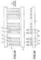
- Figs. 1A and 1B are respectively plan view and cross-sectional view of the electrode structure, showing a first embodiment of unidirectional transducer for the surface acoustic wave filter device according to the present invention.
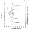
- Fig. 2 is a graph showing the frequency characteristic of the unidirectional transducer of Figs. 1A and 1B.
- Figs, 3A and 3B are respectively plan view and cross-sectional view of the electrode structure showing a second embodiment of the unidirectional transducer according to the present invention.
- Fig. 4 is a graph showing the frequency characteristic of the unidirectional transducer of Figs. 3A and 3B.
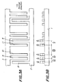
- Figs. 5A and 5B are respectively plan view and cross-sectional view of the electrode structure showing a third embodiment of the unidirectional transducer according to the present invention.
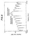
- Fig. 6 is a graph showing the frequency characteristic of the unidirectional transducer of Figs. 5A and 5B.
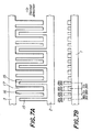
- Figs. 7A and 7B are respectively plan view and cross-sectional view of the electrode structure showing a fourth embodiment of the unidirectional transducer according to the present invention.
- Fig. 8 is a graph showing the frequency characteristic of the unidirectional transducer of Figs. 7A and 7B.
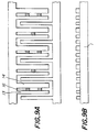
- Figs. 9A and 9B are respectively plan view and cross-sectional view of the electrode structure showing a fifth embodiment of the unidirectional transducer according to the present invention.
- Figs. 10A and 10B are respectively plan view and cross-sectional view of the electrode structure showing a sixth embodiment of the unidirectional transducer according to the present invention.
- Fig. 11 shows one example of the calculated results on the filter device according to the present invention wherein the unidirectional transducers of Figs. 10A and 10B are formed on a GaAs substrate.
- Fig. 12 shows another example of the calculated results on the filter device according to the present invention wherein the unidirectional transducers of Figs. 10A and 10B are formed on a quartz substrate.
- Fig. 13 shows still another example of the calculated results on the unidirectional characteristics of the filter device according to the present invention wherein the unidirectional transducers of Figs, 10A and 10B are formed on a LiNbO3 substrate.
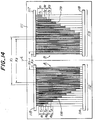
- Fig. 14 is a diagram showing the structure of an embodiment of the surface acoustic wave filter device according to the present invention.
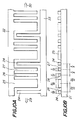
- Fig. 15 is a diagram showing in detail a part of an input-side transducer.
- Fig. 16 is a diagram showing a modified example of the surface acoustic wave filter shown in Fig. 14.
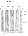
- Fig. 17 is a diagram showing the layout constitution of a dummy electrode.
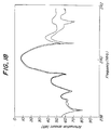
- Fig. 18 is a graph showing a passband characteristic of the acoustic surface-wave filter showing in Fig. 14.
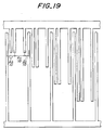
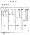
- Figs. 19 to 25 are diagrams showing various modifications of a transducer which amplifies a second harmonic wave.
- the surface acoustic wave filter device includes a substrate 1 which comprises a piezoelectric and electrostrictive material or a piezoelectric thin film.
- Unidirectional surface acoustic wave transducers comprising interdigital-type positive and negative electrodes 2, 3 are arranged on input and output sides, on the surface of the substrate 1, to excite surface acoustic wave and to receive transmitted surface acoustic wave.
- the present invention provides an internal reflection-type unidirectional surface acoustic wave transducer which operates at an operational angular frequency N ⁇ where ⁇ is the operational angular frequency corresponding to the wavelength ⁇ of the fundamental surface acoustic wave of the transducer, and N is an integer (1, 2, 3, and so on).
- the surface acoustic wave filter device incorporating such unidirectional transducer serves to amplify and convert a harmonic wave of the fundamental surface acoustic wave, making it possible to increase the electrode finger width and to thereby significantly improve the manufacturing yield.
- FIG. 1A and 1B A first embodiment of the interdigital-type unidirectional transducer according to the present invention is shown in Figs. 1A and 1B.
- the transducer is formed by periodically arranging a positive electrode finger 4 with a width ⁇ /10, a negative electrode finger 5 with a width of ⁇ /10 spaced from the positive electrode finger 4 by a center distance ⁇ /5, a negative electrode finger 6 of a width ⁇ /10 spaced from the negative electrode finger 5 by a center distance ⁇ /5, a negative electrode finger 7 of a width ⁇ /10 spaced from the negative electrode finger 6 by a center distance 2 ⁇ /5, and a positive electrode finger 4 with a width ⁇ /10 spaced from the negative electrode finger 7 by a center distance ⁇ /5, where ⁇ is the wave length of the fundamental surface acoustic wave at the fundamental operational frequency.
- said center distances and said electrode finger widths may be within a range of ⁇ 20%.
- a simulation test has been performed with respect to the frequency characteristic of the filter device with the arrangement of the unidirectional surface acoustic wave transducers shown in Figs. 1A and 1B.
- the result of the simulation test is shown in Fig. 2.
- the transducer includes interdigital-type electrodes formed by periodically arranging a positive electrode finger 8 with a width ⁇ /10, a negative electrode finger 9 with a width ⁇ /10 spaced from the positive electrode finger 8 by a center distance 7 ⁇ /40, a negative electrode finger 10 of a width ⁇ /10 spaced from the negative electrode finger 9 by a center distance 7 ⁇ /40, a negative electrode finger 11 of a width ⁇ /10 spaced from the negative electrode finger 10 by a center distance 19 ⁇ /40, and a positive electrode finger 8 with a width ⁇ /10 spaced from the negative electrode finger 11 by a center distance 7 ⁇ /40.
- said center distances and said electrode finger widths may be within a range of ⁇ 20%.
- the transducer includes interdigital-type electrodes formed by periodically arranging a positive electrode finger 12 with a width 3 ⁇ /20, a negative electrode finger 13 with a width 3 ⁇ /20 spaced from the positive electrode finger 12 by a center distance 6 ⁇ /20, a negative electrode finger 14 of a width 5 ⁇ /20 spaced from the negative electrode finger 13 by a center distance 7 ⁇ /20, and a positive electrode finger 12 of a width 3 ⁇ /20 spaced from the negative electrode finger 14 by a center distance 7 ⁇ /20.
- said center distances and said electrode finger widths may be within a range of ⁇ 20%.
- the transducer includes interdigital-type electrodes formed by periodically arranging a positive electrode finger 15 with a width 29 ⁇ /200, a negative electrode finger 16 with a width 29 ⁇ /200 spaced from the positive electrode finger 15 by a center distance 29 ⁇ /100, a negative electrode finger 17 of a width 55 ⁇ /200 spaced from the negative electrode finger 16 by a center distance 71 ⁇ /200, and a positive electrode finger 15 with a width 29 ⁇ /200 spaced from the negative electrode finger 16 by a center distance 71 ⁇ /200.
- said center distances and said electrode finger widths may be within a range of ⁇ 20%.
- FIG. 9 A fifth embodiment of the unidirectional surface acoustic wave transducer according to the present invention is shown in Fig. 9.
- the transducer includes interdigital-type electrodes 13 and 14 which are of the same electrode film thickness and the same material, and which are partially connected to each other for controlling the unidirectional degree of the internal reflector.
- each wave phase becomes in-phase at a center frequency.
- the range of ⁇ 20% is considered suitable.
- the internal reflection-type unidirectional surface acoustic wave transducer of the above-mentioned embodiments may be combined with a bidirectional surface acoustic wave transducer which is formed at the center of the substrate.
- the unidirectional transducers with above structure are arranged on both sides of the bidirectional transducer with an orientation whereby the wave energy in increased toward the center.
- the lower side and the upper side of the plan view were defined as the positive electrode 2 and the negative electrode 3, respectively.
- FIG. 10A and 10B A sixth embodiment of the unidirectional surface acoustic wave transducer according to the present invention is shown in Figs. 10A and 10B, wherein the substrate is denoted by reference numeral 21, and the negative electrode and the positive electrode are denoted by reference numerals 22, 23, respectively.
- the transducer includes interdigital-type electrodes formed by periodically arranging a positive electrode finger 24 with a width ⁇ /10, a negative electrode finger 25 with a width 3 ⁇ /10 spaced from the positive electrode finger 24 by a center distance 3 ⁇ /10, a negative electrode finger 26 with a width ⁇ /10 spaced from the negative electrode finger 25 by a center distance 3 ⁇ /10, a negative electrode finger 27 of a width ⁇ /10 spaced from the negative electrode finger 26 by a center distance ⁇ /5, and a positive electrode finger 24 with a width ⁇ /10 spaced from the negative electrode finger 27 by a center distance ⁇ /5.
- the electrode finger widths and the center distances are accurately the abovementioned values, provided that the phase of each wave becomes in-phase at the center frequency.
- the value is within the range of ⁇ 80%.
- Fig. 11 shows one example whereby a low insertion loss has been obtained by arranging the unidirectional transducers on a GaAs substrate in the direction facing the directional properties each other.
- the normal direction is shown by arrow 29 in Fig. 10A.
- the length of the electrode finger L is 200 ⁇ 2 where ⁇ 2 is the wavelength of the second harmonic wave.
- reference numeral 31 shows the normal direction characteristics, and its insertion loss is 0.5dB.
- Fig. 12 shows another example whereby a low insertion loss has been obtained by arranging the unidirectional transducers on a quartz substrate in the direction facing each other.
- the length of the electrode finger L is 350 ⁇ 2
- the insertion loss is 1.0dB.
- the normal direction is shown by arrow 30 in Fig. 10A.
- Fig. 13 shows the result of the directional property when using LiNbO3 substrate provided with the above-mentioned unidirectional transducers.
- the directional property is also small as 3.6dB.
- Figs. 14 and 15 a structural example of the surface acoustic wave filter device according to still another embodiment of the present invention.
- Fig. 14 is a plan view showing the entire structure
- Fig. 15 is a plan view showing part of Fig. 14 in an enlarged scale.
- the filter device includes a piezoelectric substrate 111 comprising quartz, and an input-side transducer 112 and an output-side transducer 113 both formed on the substrate 111.
- the input-side and the output-side transducers are constituted of unidirectional transducers which suppress excitation and reception level of the fundamental wave, and amplifies and converts the second harmonic wave.
- the input-side and the output-side transducers are arranged symmetrically with respect to the center line L perpendicular to the propagation direction of the acoustic surface-wave. Since the input-side and the output-side transducers have the same electrode structure, the input-side transducer will be explained as an example of. the electrode structure.
- the input-side transducer 112 includes an interdigital-type positive electrode 114, an interdigital-type negative electrode 115, and a shunt-type floating electrode 116 arranged between the positive and the negative electrodes.
- Each electrode finger of the positive electrode 114 is formed with a pitch ⁇ .
- the two electrode fingers 115a and 115b of the negative electrode 15 are formed between the two electrode fingers 114a and 114b of the positive electrode 114 which are adjacent to each other.
- the electrode fingers of the floating electrode 116 are formed between the electrode fingers of the negative electrodes.
- the electrode finger of the floating electrode 116 is formed between the two negative electrode fingers 115a and 115b and establishes only a mechanical reflection effect without carrying out any excitation operation.
- the floating electrode 116 performs the same function as that of a normal floating electrode which is electrically in a floated state. Therefore, the floating electrode 116 becomes shunt-type where respective electrode fingers are electrically connected to each other by way of the negative electrode 115.
- the floating electrode may be either one type which is electrically in a floated state, and another type in which respective electrode fingers are electrically connected to each other via the positive or negative electrode.
- the center distance between the electrode finger 114a of the positive electrode 114 and the electrode finger 115a of the negative electrode 115 is 7 ⁇ /40
- the center distance between the other electrode finger 114b of the positive electrode 114 and the other electrode finger 115b of the negative electrode 115 is 8 ⁇ /40.
- the electrode finger of the floating electrode 116 is formed to have a center distance 14 ⁇ /40 with reference to the electrode finger 114a of the positive electrode. For example, in the case of an surface acoustic wave filter device having a passband width of an intermediate frequency of 240 MHz, the wavelength ⁇ of the fundamental surface acoustic wave is approximately 26.3 ⁇ m.
- the positive electrode, the negative electrode and the floating electrode of the input-side transducer 112 and the output-side transducer 113 are arranged in accordance with the weighting method.
- the region where the positive electrode 114, the negative electrode 115 and the floating electrode 116 of the input-side transducer 112 are formed defines an exciting area which is divided into a plurality of tracks T1, T2, T3, ..., T n-1 , T n .
- Each of the tracks extends in the propagation direction of the acoustic surface-wave.
- the floating electrode 116 is arranged between the adjacent electrode fingers of the positive electrode 114 and the negative electrode 115.
- the region where the positive electrode 117, the negative electrode 118, and the floating electrode 119 are formed constitutes a receiving area which is divided into a plurality of tracks t1, t2, t3, ..., t n-1 , t n .
- the distance between the track Ti of the input-side transducer 12 and the corresponding track ti of the output-side transducer 13 is defined as a track length x i .
- the track length x i as shown in Fig. 14, may be defined as the distance between the electrode fingers of the innermost side of each track.
- the length xi of the tracks vary in a linear manner.
- the difference (x i - x i-1 ) (2 ⁇ i ⁇ n) between the lengths of adjacent tracks is set to a constant value which is ⁇ /2 multiplied by an integer.
- the track width which is in the direction perpendicular to the propagation direction of the surface acoustic wave is defined. That is, the track widths of the tracks T1, T2, ..., T n , and t1, t2, ..., t n are represented by a1, a2, ..., a n .
- the track widths a1, a2, ..., a n are defined in accordance with a desired function which may be an appropriate window function, such as Kaiser function, Hamming function, Hanning function, etc.
- the track lengths x1, x2, ..., x n linearly reduce at a fixed distance 2 ⁇ and the track widths a1, a2, ..., a n change according to Kaiser function. Therefore, the track width is set at the maximum value in the central track and is gradually reduced as it goes toward the end portion of the track array.
- the unidirectional transducer weighted in distance has the characteristic weighted depending on the distance between the transmission and reception portions and the aperture length, the side-lobe can be effectively suppressed in comparison with a transducer which does not add distance weighting.
- the unidirectional transducer weighted in distance is advantageous in that the impedance at the input-side can be matched with the impedance at the output-side can be obtained, and further in that the number of electrode pairs can be reduced.
- non-excitation area A where only the electrode fingers of the negative electrode 115 of the input-side transducer 112 are formed
- non-receiving area B where only the electrode fingers of the positive electrode 117 of the output-side transducer 113 are formed.
- the center frequency of the weighting function shifts so that a problem may arise that, in the frequency characteristics, the characteristic near the center frequency and the side-lobe at higher frequency side with reference to the center frequency become higher.
- the occurrence of difference in the average propagation velocity of the surface acoustic wave is avoided by arranging dummy electrodes in the non-excitation area A and the non-receiving area B in which are arranged the electrode fingers of either a positive electrode or a negative electrode only.
- Fig. 16 shows the entire structure of the surface acoustic wave filter device where dummy electrode groups 120 and 121 are formed in the device of Fig. 14, A part of the input-side transducer is shown typically in Fig. 17.
- the respective electrode fingers 120a to 120d of the dummy electrode group 120 are formed along the extended line of the electrode fingers of the positive electrode 114 and according to the lengths of the respective electrode fingers.
- the electrode fingers are present in uniform density in the area between the input-side transducer 112 and the output-side transducer 113.
- the electrode fingers 120a to 120d of the dummy electrode are formed integrally with the negative electrode 115 and used as a shunt-type dummy electrode.
- the open-type floating electrode and the shunt-type floating electrode have the same sign of reflection coefficient to each other. It is thus possible to selectively use a dummy electrode of shunt-type or open-type.
- the dummy electrode groups 122 and 123 are also formed respectively on the opposite side with respect to the side where the input-side transducer 112 confronts to the output-side transducer 113 shown in Fig. 17.
- the filter device having the structure shown in Figs. 14 and 15 was formed on a quartz substrate and the attenuation characteristics were measured.
- the results of the measurement are shown in Fig. 18.
- the broken line shows the measured result of a filter device without dummy electrodes, and the solid line shows the measured result of a filter device with the dummy electrodes.
- the insertion loss is suppressed to a lower value of 7dB.
- the attenuation of the first side-lobe is approximately 30dB.
- the attenuation becomes to 37dB to realize an excellent attenuation characteristics. From the results of the measurement, it is clear that a second harmonic wave is amplified and converted. Provision of the dummy electrodes serves to further improve the side-lobe characteristic on higher frequency with reference to the center frequency.
- the transducer shown in Fig. 19 has a structure similar to that of the transducer shown in Fig. 15. There is only difference in that the pitch of the electrode fingers is set to 2 ⁇ /10, 2 ⁇ /10, 4 ⁇ /10 and 2 ⁇ /10 in serial order along the propagation direction of the surface acoustic wave.
- the transducer shown in Fig. 20 is also the one suitable for a quartz substrate with a small electromechanical coupling coefficient.
- the electrode fingers 130a to 130d of the positive electrode 130 with an electrode width of ⁇ /10 are formed in serial order with a pitch which is same as the wavelength ⁇ of the fundamental wave.
- the negative electrode 131 has three kinds of electrode fingers 131a, 131b and 131c which are also set in serial order with a pitch ⁇ .
- the width of the electrode finger 131a is 3 ⁇ /10 and the widths of the electrode fingers 131b and 131c are to ⁇ /10.
- the center distances between the electrode fingers, as shown in Fig. 20, are made as 3 ⁇ /10, 3 ⁇ /10, 2 ⁇ /10 and 2 ⁇ /10.
- the electrode finger 131b acts as a shunt-type floating electrode.
- Such an electrode structure can realize a second harmonic surface acoustic wave filter device which amplifies a second harmonic wave and having good characteristics.
- Fig. 21 also shows a second harmonic transducer suitable for the quartz substrate.
- the respective electrode fingers of the positive electrode 140 have their width set at 29 ⁇ /200 and are formed in serial order with a pitch of ⁇ .
- the negative electrode 141 has an electrode finger 141a with an electrode width of 29 ⁇ /200 and an electrode finger 141b with the electrode width of 55 ⁇ /200. These electrode fingers are also formed in serial order with the pitch of ⁇ .
- the center distances between the respective electrode fingers are 58 ⁇ /200, 71 ⁇ /200 and 71 ⁇ /200.
- the electrode finger 141b functions as a floating electrode because the end side confronting the electrode finger 141a does not perform the exciting function and has a strong mechanical reflection effect, and the end side confronting the positive electrode 140 achieves the exciting function and serves as an electrode finger for excitation.
- Fig. 22 shows a structure which is similar to the transducer of Fig. 21. There is only a difference in that the layout pitches of the respective electrode fingers are set to 6 ⁇ /20, 7 ⁇ /20 and 7 ⁇ /20 in serial order along the propagation direction of the surface acoustic wave.
- Fig. 23 shows a second harmonic transducer suitable for a LiNbO3 substrate with a high electromechanical coupling coefficient.
- Respective electrode fingers of the positive electrode 150 has an electrode width of ⁇ /10 and is arranged with a pitch ⁇ .
- the negative electrode 151 has an electrode finger 151a with the electrode width ⁇ /10, and an electrode finger 51b with the electrode width 3 ⁇ /10.
- the open-type floating electrode 151 is arranged between the electrode fingers 151a and 151b of the negative electrode.
- Each center distance between the electrode fingers, as shown in Fig. 23, is set to 2 ⁇ /10, 2 ⁇ /10, 3 ⁇ /10 and 3 ⁇ /10.
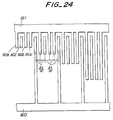
- Fig. 24 also shows the structure of a second harmonic transducer suitable for a LiNbO3 substrate.
- Respective electrode fingers of the positive electrode 160 has the electrode width ⁇ /10, and is formed in serial order with a pitch ⁇ .
- the negative electrode 161 has three kinds of electrode fingers 161a, 161b and 161c and they are formed in serial order with a pitch ⁇ , respectively.
- the electrode widths of the electrode fingers are ⁇ /10, respectively.
- the center distances between the respective electrode fingers is set with equal internal of 2 ⁇ /10.
- the electrode finger 161b of the negative electrode acts as a shunt-type floating electrode, so that it takes a form in which the open-type floating electrode 162 and the shunt-type floating electrode 161b are combined.
- Fig. 25 shows the structure of transducer suitable for both of quartz substrate and LiNbO3 substrate.
- the positive electrode 170 has an electrode width of ⁇ /8 and is formed in serial order with a pitch ⁇ .
- the negative electrode 171 has an electrode 171a of an electrode width 3 ⁇ /8 and an electrode finger 171b of an electrode width of ⁇ /8.
- the electrode fingers are formed in serial order with a pitch ⁇ .
- the center distances between respective electrode fingers are 3 ⁇ /8, 3 ⁇ /8 and 2 ⁇ /8.
- a crystal is used as a material having a small electrical and mechanical coupling coefficient in the embodiment, however, another material such as Li2B4O7 can be used.
- the unidirectional acoustic surface-wave transducer according to the present invention is constructed as described above. Therefore, it can be generally manufactured at a low cost which is comparable with that of ordinary acoustic surface-wave device. This is because an electrode can be formed by a single cycle step including evaporation, exposure and etching, and it is unnecessary to provide a special phase shifter for obtaining the unidirectional transducer.
- the transducer in accordance with the present invention is used as an input/output transducer, it is possible to minimize the ripple due to TTE (triple transit echo) which is inherent property of unidirectional transducers, because there are no factors which result in undesirable loss. Therefore, the present invention is particularly effective to realize a filter device with a small insertion loss, which can be manufactured at a low cost.
- the electrode structure in conjunction with amplification and conversion of a higher-order harmonic wave with respect to the fundamental surface acoustic wave defined by the pitch of electrode, the electrode structure is defined in accordance with a distance weighting method, it is possible to improve the side-lobe characteristic of the surface acoustic wave filter device for converting the higher-order harmonic wave. As the result, the manufacturing yield of the surface acoustic wave filter device is further improved. Furthermore, provision of the dummy electrodes makes it possible to avoid degradation of the frequency shift characteristics, and further improve the side-lobe characteristics in the higher frequency side with reference to the center frequency.
Landscapes
- Physics & Mathematics (AREA)
- Acoustics & Sound (AREA)
- Surface Acoustic Wave Elements And Circuit Networks Thereof (AREA)
Applications Claiming Priority (6)
| Application Number | Priority Date | Filing Date | Title |
|---|---|---|---|
| JP215370/92 | 1992-07-02 | ||
| JP4215370A JP3035085B2 (ja) | 1992-07-02 | 1992-07-02 | 一方向性弾性表面波変換器 |
| JP361917/92 | 1992-12-22 | ||
| JP4361917A JP2583384B2 (ja) | 1992-12-22 | 1992-12-22 | 内部反射形一方向性弾性表面波変換器及びこれを用いた電子装置 |
| JP4536293A JPH06260879A (ja) | 1993-03-05 | 1993-03-05 | 弾性表面波フィルタ装置 |
| JP45362/93 | 1993-03-05 |
Publications (2)
| Publication Number | Publication Date |
|---|---|
| EP0580307A1 true EP0580307A1 (fr) | 1994-01-26 |
| EP0580307B1 EP0580307B1 (fr) | 1998-10-07 |
Family
ID=27292205
Family Applications (1)
| Application Number | Title | Priority Date | Filing Date |
|---|---|---|---|
| EP93305195A Expired - Lifetime EP0580307B1 (fr) | 1992-07-02 | 1993-07-02 | Dispositif de filtrage à ondes acoustiques de surface |
Country Status (3)
| Country | Link |
|---|---|
| US (1) | US5438306A (fr) |
| EP (1) | EP0580307B1 (fr) |
| DE (1) | DE69321414T2 (fr) |
Cited By (2)
| Publication number | Priority date | Publication date | Assignee | Title |
|---|---|---|---|---|
| RU2195069C1 (ru) * | 2002-04-08 | 2002-12-20 | Зао Нпп "Элко" | Однонаправленный преобразователь поверхностных акустических волн |
| EP1243947A3 (fr) * | 2001-03-21 | 2004-04-14 | Carl Zeiss | Elément optique diffractif, système d'illumination et système et procédé d'exposition |
Families Citing this family (14)
| Publication number | Priority date | Publication date | Assignee | Title |
|---|---|---|---|---|
| JPH0685597A (ja) * | 1992-09-02 | 1994-03-25 | Mitsubishi Electric Corp | 弾性表面波装置 |
| FR2695771B1 (fr) * | 1992-09-15 | 1994-10-28 | Thomson Csf | Transducteur d'ondes unidirectionnel. |
| US5703427A (en) * | 1993-03-19 | 1997-12-30 | Thomson-Csf | Surface-wave distributed acoustic reflection transducer and filter including such a transducer |
| US5793146A (en) * | 1993-11-12 | 1998-08-11 | Rf Monolithics, Inc. | Surface acoustic wave transducer having selected reflectivity |
| JP3484237B2 (ja) * | 1994-09-28 | 2004-01-06 | 日本碍子株式会社 | 弾性表面波デバイス |
| US5663695A (en) * | 1994-10-31 | 1997-09-02 | Ngk Insulators, Ltd. | Surface acoustic wave filter device and transducer therefor |
| JPH10135765A (ja) * | 1996-10-30 | 1998-05-22 | Nec Corp | 一方向性弾性表面波フィルタ |
| US5952765A (en) * | 1996-11-26 | 1999-09-14 | Trw Inc. | Reduced coupling saw filter |
| JPH10256870A (ja) * | 1997-03-14 | 1998-09-25 | Ngk Insulators Ltd | 弾性表面波デバイス |
| DE19907640A1 (de) * | 1998-03-25 | 1999-10-07 | Dresden Ev Inst Festkoerper | Akustisches Oberflächenwellenbauelement |
| US6246150B1 (en) * | 1999-10-28 | 2001-06-12 | Kabushiki Kaisha Toshiba | Surface acoustic wave device |
| US6825794B2 (en) * | 2000-06-02 | 2004-11-30 | Research In Motion Limited | Wireless communication system using surface acoustic wave (SAW) second harmonic techniques |
| DE102009002605B4 (de) * | 2009-04-23 | 2014-02-13 | Leibniz-Institut Für Festkörper- Und Werkstoffforschung Dresden E.V. | Unidirektionaler Wandler für akustische Oberflächenwellen |
| DE102019113282A1 (de) * | 2019-05-20 | 2020-11-26 | RF360 Europe GmbH | Akustische Verzögerungskomponente |
Citations (1)
| Publication number | Priority date | Publication date | Assignee | Title |
|---|---|---|---|---|
| US3987376A (en) * | 1974-03-22 | 1976-10-19 | Hazeltine Corporation | Acoustic surface wave device with harmonic coupled transducers |
Family Cites Families (7)
| Publication number | Priority date | Publication date | Assignee | Title |
|---|---|---|---|---|
| US3727155A (en) * | 1972-03-20 | 1973-04-10 | Zenith Radio Corp | Acoustic surface wave filter |
| US3748603A (en) * | 1972-03-27 | 1973-07-24 | Zenith Radio Corp | Surface wave filter with reflection suppression |
| JPS5610724A (en) * | 1979-07-09 | 1981-02-03 | Toshiba Corp | Elastic surface wave transducer |
| JPS62210713A (ja) * | 1986-03-12 | 1987-09-16 | Kazuhiko Yamanouchi | 弾性表面波共振器 |
| JP2779675B2 (ja) * | 1989-12-31 | 1998-07-23 | 和彦 山之内 | 弾性表面波デバイス及び弾性表面波フィルタ |
| JPH04138710A (ja) * | 1990-09-28 | 1992-05-13 | Nec Corp | 弾性表面波フィルタ |
| JP3096102B2 (ja) * | 1991-08-29 | 2000-10-10 | 和彦 山之内 | 弾性表面波フィルタ装置 |
-
1993
- 1993-07-01 US US08/085,121 patent/US5438306A/en not_active Expired - Lifetime
- 1993-07-02 DE DE69321414T patent/DE69321414T2/de not_active Expired - Fee Related
- 1993-07-02 EP EP93305195A patent/EP0580307B1/fr not_active Expired - Lifetime
Patent Citations (1)
| Publication number | Priority date | Publication date | Assignee | Title |
|---|---|---|---|---|
| US3987376A (en) * | 1974-03-22 | 1976-10-19 | Hazeltine Corporation | Acoustic surface wave device with harmonic coupled transducers |
Non-Patent Citations (3)
| Title |
|---|
| IEEE TRANSACTIONS ON MICROWAVE THEORY AND TECHNIQUES vol. 33, no. 6, June 1985, NEW YORK US pages 510 - 518 MITSUTAKA HIKITA ET AL '800-MHZ HIGH-PERFORMANCE SAW FILTER USING NEW RESONANT CONFIGURATION' * |
| SIEMENS FORSCHUNGS- UND ENTWICKLUNGSBERICHTE vol. 6, no. 3, 1977, BERLIN DE pages 132 - 136 A. G]NTHER ET AL 'SPEEDING UP THE ANALYSIS OF SURFACE ACOUSTIC WAVE DEVICES' * |
| YAMANOUCHI K., ET AL.: "WIDE BANDWIDTH LOW LOSS FILTERS USING PIEZOELECTRIC LEAKY SAW UNIDIRECTIONAL TRANSDUCERS WITH FLOATING ELECTRODES.", JAPANESE JOURNAL OF APPLIED PHYSICS, JAPAN SOCIETY OF APPLIED PHYSICS, JP, vol. 30., no. SUPPL.30-1., 1 January 1991 (1991-01-01), JP, pages 173 - 175., XP000305676, ISSN: 0021-4922 * |
Cited By (3)
| Publication number | Priority date | Publication date | Assignee | Title |
|---|---|---|---|---|
| EP1243947A3 (fr) * | 2001-03-21 | 2004-04-14 | Carl Zeiss | Elément optique diffractif, système d'illumination et système et procédé d'exposition |
| US6885491B2 (en) | 2001-03-21 | 2005-04-26 | Carl-Zeiss-Stiftung (Trading As Carl Zeiss) | Diffraction-optical component, illumination system and exposure system comprising such a diffraction-optical component as well as an exposure method employing such an exposure system |
| RU2195069C1 (ru) * | 2002-04-08 | 2002-12-20 | Зао Нпп "Элко" | Однонаправленный преобразователь поверхностных акустических волн |
Also Published As
| Publication number | Publication date |
|---|---|
| DE69321414T2 (de) | 1999-04-01 |
| US5438306A (en) | 1995-08-01 |
| EP0580307B1 (fr) | 1998-10-07 |
| DE69321414D1 (de) | 1998-11-12 |
Similar Documents
| Publication | Publication Date | Title |
|---|---|---|
| EP0580307B1 (fr) | Dispositif de filtrage à ondes acoustiques de surface | |
| US7135805B2 (en) | Surface acoustic wave transducer | |
| US6127904A (en) | Surface acoustic wave filter having unidirectional and bidirectional transducers | |
| EP0585863B1 (fr) | Dispositif à ondes acoustiques de surface | |
| US5986523A (en) | Edge reflection type longitudinally coupled surface acoustic wave filter | |
| WO2000076067A1 (fr) | Filtre a ondes de surface | |
| JP3414373B2 (ja) | 弾性表面波装置 | |
| EP0840446B1 (fr) | Filtre unidirectionnel à ondes acoustiques de surface | |
| EP0530041B1 (fr) | Transducteur à électrodes flottants pour génération d'ondes acoustiques de surface unidirectionnelles | |
| EP0026114A1 (fr) | Dispositif à ondes acoustiques de surface | |
| EP0562876B1 (fr) | Dispositif de filtrage à ondes acoustiques de surface | |
| US4513261A (en) | Low-loss acoustic wave filter device | |
| US5714830A (en) | Free edge reflective-type surface acoustic wave device | |
| EP0802627B1 (fr) | Convertisseur d'ondes sonores de surface et dispositif de filtrage acoustique l'utilisant | |
| JP3298251B2 (ja) | 弾性表面波装置 | |
| US7102269B2 (en) | Surface acoustic wave device | |
| JPH05183378A (ja) | 弾性表面波素子 | |
| JP4379143B2 (ja) | トランスバーサル型弾性表面波フィルタ | |
| JP4385277B2 (ja) | 弾性表面波変換器とこれを用いた電子装置 | |
| JP3035085B2 (ja) | 一方向性弾性表面波変換器 | |
| JP3420051B2 (ja) | 弾性表面波フィルタ装置及びこれに用いる一方向性変換器 | |
| Tsutsumi et al. | A novel reflector-filter using a SAW waveguide directional coupler | |
| JP3394362B2 (ja) | 弾性表面波装置 | |
| Mishima et al. | IIDT type SAW filter using acoustic reflection cancel condition with solid IDT | |
| JPH08213870A (ja) | 弾性表面波フィルタ装置及びこれに用いる変換器 |
Legal Events
| Date | Code | Title | Description |
|---|---|---|---|
| PUAI | Public reference made under article 153(3) epc to a published international application that has entered the european phase |
Free format text: ORIGINAL CODE: 0009012 |
|
| AK | Designated contracting states |
Kind code of ref document: A1 Designated state(s): DE FR GB |
|
| 17P | Request for examination filed |
Effective date: 19940511 |
|
| GRAG | Despatch of communication of intention to grant |
Free format text: ORIGINAL CODE: EPIDOS AGRA |
|
| 17Q | First examination report despatched |
Effective date: 19970924 |
|
| GRAG | Despatch of communication of intention to grant |
Free format text: ORIGINAL CODE: EPIDOS AGRA |
|
| GRAG | Despatch of communication of intention to grant |
Free format text: ORIGINAL CODE: EPIDOS AGRA |
|
| GRAH | Despatch of communication of intention to grant a patent |
Free format text: ORIGINAL CODE: EPIDOS IGRA |
|
| GRAH | Despatch of communication of intention to grant a patent |
Free format text: ORIGINAL CODE: EPIDOS IGRA |
|
| GRAA | (expected) grant |
Free format text: ORIGINAL CODE: 0009210 |
|
| AK | Designated contracting states |
Kind code of ref document: B1 Designated state(s): DE FR GB |
|
| REF | Corresponds to: |
Ref document number: 69321414 Country of ref document: DE Date of ref document: 19981112 |
|
| ET | Fr: translation filed | ||
| PLBE | No opposition filed within time limit |
Free format text: ORIGINAL CODE: 0009261 |
|
| STAA | Information on the status of an ep patent application or granted ep patent |
Free format text: STATUS: NO OPPOSITION FILED WITHIN TIME LIMIT |
|
| 26N | No opposition filed | ||
| REG | Reference to a national code |
Ref country code: GB Ref legal event code: IF02 |
|
| PGFP | Annual fee paid to national office [announced via postgrant information from national office to epo] |
Ref country code: GB Payment date: 20060614 Year of fee payment: 14 |
|
| PGFP | Annual fee paid to national office [announced via postgrant information from national office to epo] |
Ref country code: FR Payment date: 20060705 Year of fee payment: 14 |
|
| PGFP | Annual fee paid to national office [announced via postgrant information from national office to epo] |
Ref country code: DE Payment date: 20060731 Year of fee payment: 14 |
|
| GBPC | Gb: european patent ceased through non-payment of renewal fee |
Effective date: 20070702 |
|
| PG25 | Lapsed in a contracting state [announced via postgrant information from national office to epo] |
Ref country code: DE Free format text: LAPSE BECAUSE OF NON-PAYMENT OF DUE FEES Effective date: 20080201 |
|
| PG25 | Lapsed in a contracting state [announced via postgrant information from national office to epo] |
Ref country code: GB Free format text: LAPSE BECAUSE OF NON-PAYMENT OF DUE FEES Effective date: 20070702 |
|
| REG | Reference to a national code |
Ref country code: FR Ref legal event code: ST Effective date: 20080331 |
|
| PG25 | Lapsed in a contracting state [announced via postgrant information from national office to epo] |
Ref country code: FR Free format text: LAPSE BECAUSE OF NON-PAYMENT OF DUE FEES Effective date: 20070731 |