EP0580437A2 - Moyen d'enregistrement, appareil d'enregistrement à jet d'encre et méthode de récupération - Google Patents
Moyen d'enregistrement, appareil d'enregistrement à jet d'encre et méthode de récupération Download PDFInfo
- Publication number
- EP0580437A2 EP0580437A2 EP93305800A EP93305800A EP0580437A2 EP 0580437 A2 EP0580437 A2 EP 0580437A2 EP 93305800 A EP93305800 A EP 93305800A EP 93305800 A EP93305800 A EP 93305800A EP 0580437 A2 EP0580437 A2 EP 0580437A2
- Authority
- EP
- European Patent Office
- Prior art keywords
- ink
- recording
- ejection
- cap
- carriage
- Prior art date
- Legal status (The legal status is an assumption and is not a legal conclusion. Google has not performed a legal analysis and makes no representation as to the accuracy of the status listed.)
- Granted
Links
- 238000000034 method Methods 0.000 title claims description 17
- 238000011084 recovery Methods 0.000 title description 51
- 239000000463 material Substances 0.000 claims abstract description 101
- 239000003570 air Substances 0.000 claims description 55
- 238000004891 communication Methods 0.000 claims description 24
- 230000000694 effects Effects 0.000 claims description 15
- 238000009835 boiling Methods 0.000 claims description 9
- 239000012080 ambient air Substances 0.000 claims description 6
- 239000011358 absorbing material Substances 0.000 claims description 5
- 230000007246 mechanism Effects 0.000 abstract description 6
- 239000000976 ink Substances 0.000 description 481
- 239000007788 liquid Substances 0.000 description 24
- 238000004140 cleaning Methods 0.000 description 17
- 238000007789 sealing Methods 0.000 description 17
- 238000012360 testing method Methods 0.000 description 17
- 239000003086 colorant Substances 0.000 description 12
- 239000013013 elastic material Substances 0.000 description 12
- 239000002699 waste material Substances 0.000 description 11
- 230000002829 reductive effect Effects 0.000 description 10
- 230000008859 change Effects 0.000 description 9
- 230000006866 deterioration Effects 0.000 description 9
- 238000006073 displacement reaction Methods 0.000 description 9
- 238000011109 contamination Methods 0.000 description 7
- 230000005499 meniscus Effects 0.000 description 7
- 239000007787 solid Substances 0.000 description 7
- 230000008901 benefit Effects 0.000 description 6
- 238000002156 mixing Methods 0.000 description 6
- 238000005549 size reduction Methods 0.000 description 6
- 230000002457 bidirectional effect Effects 0.000 description 5
- 230000007774 longterm Effects 0.000 description 5
- 230000004044 response Effects 0.000 description 5
- 239000000428 dust Substances 0.000 description 4
- 238000004519 manufacturing process Methods 0.000 description 4
- 239000003595 mist Substances 0.000 description 4
- 239000003795 chemical substances by application Substances 0.000 description 3
- 230000008602 contraction Effects 0.000 description 3
- 238000011161 development Methods 0.000 description 3
- 229920001971 elastomer Polymers 0.000 description 3
- 238000001704 evaporation Methods 0.000 description 3
- 238000010438 heat treatment Methods 0.000 description 3
- 239000000203 mixture Substances 0.000 description 3
- 230000004048 modification Effects 0.000 description 3
- 238000012986 modification Methods 0.000 description 3
- 230000001960 triggered effect Effects 0.000 description 3
- XLYOFNOQVPJJNP-UHFFFAOYSA-N water Substances O XLYOFNOQVPJJNP-UHFFFAOYSA-N 0.000 description 3
- 230000015572 biosynthetic process Effects 0.000 description 2
- 230000015556 catabolic process Effects 0.000 description 2
- 230000007423 decrease Effects 0.000 description 2
- 238000006731 degradation reaction Methods 0.000 description 2
- 230000000593 degrading effect Effects 0.000 description 2
- 230000002542 deteriorative effect Effects 0.000 description 2
- 238000007599 discharging Methods 0.000 description 2
- 238000001035 drying Methods 0.000 description 2
- 230000007613 environmental effect Effects 0.000 description 2
- 230000008020 evaporation Effects 0.000 description 2
- 238000005755 formation reaction Methods 0.000 description 2
- 239000012466 permeate Substances 0.000 description 2
- 239000002985 plastic film Substances 0.000 description 2
- 229920006255 plastic film Polymers 0.000 description 2
- 239000011148 porous material Substances 0.000 description 2
- 238000001454 recorded image Methods 0.000 description 2
- 229920006395 saturated elastomer Polymers 0.000 description 2
- 230000008961 swelling Effects 0.000 description 2
- VAYOSLLFUXYJDT-RDTXWAMCSA-N Lysergic acid diethylamide Chemical compound C1=CC(C=2[C@H](N(C)C[C@@H](C=2)C(=O)N(CC)CC)C2)=C3C2=CNC3=C1 VAYOSLLFUXYJDT-RDTXWAMCSA-N 0.000 description 1
- 239000002250 absorbent Substances 0.000 description 1
- 230000002411 adverse Effects 0.000 description 1
- 230000006835 compression Effects 0.000 description 1
- 238000007906 compression Methods 0.000 description 1
- 238000005260 corrosion Methods 0.000 description 1
- 230000007797 corrosion Effects 0.000 description 1
- 230000003111 delayed effect Effects 0.000 description 1
- 230000003292 diminished effect Effects 0.000 description 1
- 238000009826 distribution Methods 0.000 description 1
- 238000005530 etching Methods 0.000 description 1
- 230000004438 eyesight Effects 0.000 description 1
- 238000007667 floating Methods 0.000 description 1
- 230000010365 information processing Effects 0.000 description 1
- 238000009434 installation Methods 0.000 description 1
- 230000006911 nucleation Effects 0.000 description 1
- 238000010899 nucleation Methods 0.000 description 1
- 230000001151 other effect Effects 0.000 description 1
- 230000036961 partial effect Effects 0.000 description 1
- 230000009955 peripheral mechanism Effects 0.000 description 1
- 238000007639 printing Methods 0.000 description 1
- 239000000047 product Substances 0.000 description 1
- 230000002035 prolonged effect Effects 0.000 description 1
- 230000009467 reduction Effects 0.000 description 1
- 230000002940 repellent Effects 0.000 description 1
- 239000005871 repellent Substances 0.000 description 1
- 239000011347 resin Substances 0.000 description 1
- 229920005989 resin Polymers 0.000 description 1
- 230000000717 retained effect Effects 0.000 description 1
- 230000002441 reversible effect Effects 0.000 description 1
- 239000004065 semiconductor Substances 0.000 description 1
- 238000000926 separation method Methods 0.000 description 1
- 238000004904 shortening Methods 0.000 description 1
- 239000002689 soil Substances 0.000 description 1
- 238000004544 sputter deposition Methods 0.000 description 1
- 239000000758 substrate Substances 0.000 description 1
- 230000002459 sustained effect Effects 0.000 description 1
- 238000007740 vapor deposition Methods 0.000 description 1
Images







Classifications
-
- B—PERFORMING OPERATIONS; TRANSPORTING
- B41—PRINTING; LINING MACHINES; TYPEWRITERS; STAMPS
- B41J—TYPEWRITERS; SELECTIVE PRINTING MECHANISMS, i.e. MECHANISMS PRINTING OTHERWISE THAN FROM A FORME; CORRECTION OF TYPOGRAPHICAL ERRORS
- B41J2/00—Typewriters or selective printing mechanisms characterised by the printing or marking process for which they are designed
- B41J2/005—Typewriters or selective printing mechanisms characterised by the printing or marking process for which they are designed characterised by bringing liquid or particles selectively into contact with a printing material
- B41J2/01—Ink jet
- B41J2/135—Nozzles
- B41J2/165—Prevention or detection of nozzle clogging, e.g. cleaning, capping or moistening for nozzles
- B41J2/16505—Caps, spittoons or covers for cleaning or preventing drying out
- B41J2/16508—Caps, spittoons or covers for cleaning or preventing drying out connected with the printer frame
Definitions
- the present invention relates to a recording means for ejecting ink onto a recording material to effect recording, an ink jet apparatus, and a recovery means.
- a recording means for ejecting ink onto a recording material to effect recording an ink jet apparatus, and a recovery means.
- an ink jet recording apparatus comprising a recovery means for recovering the performance of the ink ejection orifice of a recording head, a recording means employed in the apparatus, and recovery method.
- a recording apparatus is employed in so many types of office equipment, for example, printers, copying machines, or facsimiles. It is also used as an output means in electronic office equipment such as computers, word processors, or work stations.
- Such a recording apparatus is designed to record images (including characters) on the recording material (recording medium) such as a sheet of paper, thin plastic film, or the like, based on image data (including character data). They can be classified depending on their recording systems, for example, an ink jet, wire dot, thermal, laser beam, or the like.
- the primary scanning is carried out in the direction perpendicular to the direction (secondary scanning direction) in which the recording material is advanced, in other words, a serial scanning system is adopted.
- the recording material is set at a predetermined spot
- the image is recorded (primary scanning) by the recording means mounted on a carriage which transverses along the recording material.
- the recording material is advanced by a predetermined distance (recording material conveyance), and then, as soon as the recording material stops, the image of next line is recorded (primary scanning). This cycle is repeated until recording is made over the entire surface of the recording material.
- the scanning occurs only on the secondary scanning direction, that is, in the direction in which the recording material is conveyed.
- the recording material set at a predetermined spot is continuously advanced (pitch conveyance) while recording is simultaneously made across the entire recording line width, until recording is made over the entire surface of the recording material.
- a recording apparatus of an ink jet type (ink jet recording apparatus), which is one of the aforementioned recording apparatuses, records images by ejecting ink from the recording means (recording head) onto the recording material. It offers several advantages: the ability to effect precise recording; no need for specially treated recording material, requiring just ordinary paper, meaning low operating costs; low operating noise because of its non-impact operation; easy size reduction; or the like. There is also such an advantage that it can easily record color images with the use of two or more colors.
- the ink jet recording apparatus of the line type can further increase the recording speed, in which a recording means comprises a large number of ejection orifices aligned in the recording material width direction, over the entire recording width, in other words, a full multi-type recording means is employed.
- the ink jet recording means (recording head)
- the one which uses thermal energy for ejecting the ink allows a further size reduction. This is because it can be produced through semiconductor manufacturing processes such as etching, vapor deposition, or sputtering, in other word, electrothermal transducers, electrodes, liquid passage walls, top plates, and the like can be easily formed on a substrate, whereby a high density liquid passage arrangement (ejection orifice arrangement) can be easily realized.
- the waste ink sometimes adheres to the ejection outlet surface (surface on which the ejection orifices are arranged) of the recording head (recording means), altering the direction in which the ink is ejected, and thereby, deteriorating the picture image quality.
- the ink jet recording system when ink droplets are ejected from the recording head to be deposited on the recording material such as paper or OHP film, a mist of floating micro droplets of ink (ink mist) is generated in addition to the main ink droplets, or the ink droplets splash as they land on the recording material.
- the ejection outlet surface is wetted as this mist or splash of ink adheres.
- a head performance recovery means is provided in the ink jet recording apparatus, for maintaining the ejection outlet surface or restoring the ejection outlet surface to the normal condition.
- This ink jet head performance recovery means possesses a distinctive structure which cannot be found in other types of recording apparatuses.
- the performance maintaining or recovering means there is a capping means for preventing the faulty ejection caused by a plugged orifice or orifices, a wiping means for preventing the ejection direction from being deviated by the solidified ink adhering to the ejection outlet surface, or the like.
- the capping means is used not only for preventing the faulty ejection but also for preventing the ejection orifices from drying up. This can be accomplished by keeping it humid within the cap.
- a wiping member is provided, which wipes away the foreign matter such as the waste ink by being placed in contact with the ejection outlet surface, and then, being moved relative to the ejection outlet surface.
- the wiping member is generally a blade formed of elastic material such as rubber.
- such a wiping means also has its own problems. For example, after being in service for a long time, its begins to lose its function, or if the amount of ink to be wiped suddenly increases, its function temporarily deteriorates, and therefore, it becomes difficult for the wiping means to sustain its performance recovery function. Further, the ink, foreign matter, or the like accumulates on the blade as the wiping means, and is sometimes transferred back to the ejection outlet surface, causing thereby the misaimed ejection or the ejection failure if it plugs the ejection orifices.
- the ink transferred to the blade by wiping one of the multiple recording heads is sometimes mixed with the ink of the different color from the second recording head when the second recording is wiped, deteriorating thereby the image quality.
- the amount of the ink adhering to the blade increases, which intensifies the ill effects from the blade contamination due to the waste ink, paper dust, ink mixing, or the like. It is of course possible to employ a different structure in which each recording head is provided with a dedicated blade. However, this brings different problems such as higher costs and the need for a larger space for the blade installation.
- an ink absorbing member is generally provided as the most appropriate form of this type of cleaning means, and the ink absorbing means is made of porous material having excellent ink absorbing properties.
- This ink absorbing member is placed in contact with, and is moved relative to the wiping means such as the blade or the like, so that the foreign matter adhering to the blade is wiped away and the waste ink is absorbed away.
- the absorbing material having the best cleaning performance loses its ink absorbing power as it keeps on absorbing the ink, and therefore, it is impossible to sustain reliably its performance for an extended period.
- the ink in the liquid passage increases its viscosity as its water content or the like evaporates, and as a result, the ink becomes unsuitable for ejection, failing sometimes to be ejected by the ejection energy imparted to the ink.
- Such unsuitable ink must be forced out of the liquid passages to refresh the ink in the liquid passage.
- a recovery means comprising a suction pump or the like is employed as the ink refreshing means.
- the ink having the increased viscosity may adhere to the ejection outlet surface when it is sucked out of the liquid passage by the pump or the like.
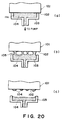
- Figure 20 is a schematic sectional view of a cap, depicting the cap movement during the performance recovery operation by suction, and at the same time, describing how the ink adheres to the ejection outlet surface during the capping operation.
- a cap 103 is airtightly placed on an ejection outlet surface 102 of a recording head 101, and a negative pressure is generated by a suction pump (unshown) connected to the cap 103, whereby the ink is sucked out of the ejection orifice.
- Figure 20(a) shows a capping stage when the above described negative pressure has been almost canceled (capping stage in which the negative pressure is canceled to a degree at which the meniscus at the ejection orifice begins to hold) after the ink is sucked out.
- An hatched area 104 represents the sucked out ink.
- the inside of the cap 103 may be assumed to be almost entirely filled with the ink.
- the cap in the capping stage shown in Figure 20(a) is moved away from the ejection outlet surface.
- the ink at the interface between the ejection outlet surface 102 and ink 104 is affected by the adhering force of the ink and the negative pressure working still to such the ink out of the ejection orifice.
- the ink tends to agglomerate due to its own surface tension. Therefore, the body of the ink 104 is constricted. in other words, the cross-sectional areas of the ink body become smaller and weaker at the locations of the constriction, and finally, the bodies of ink are severed at the conditions.
- Figure 20(c) shows a capping stage immediately after the ink body is severed at the constricted spots, leaving spots of ink on the ejection outlet surface 102 as shown in the drawing.
- the amount of the ink remaining on the ejection outlet surface 102 at this time is more than what is left because of the ink mist generated during the actual recording operation.
- the smaller the surface tension of the ink is, the larger this amount is, and that the smaller the nik repellent force of the ejection outlet surface is, the larger this amount is.
- the larger the amount of the ink adhering to the ejection outlet surface 102 is, the larger is the extent of the contamination of the apparatus interior or the recording material (recording paper).
- the negative pressure still remains within the cap immediately after the ink sucking operation, and if the cap 103 is separated at this time, that is, immediately after the ink sucking operation, the atmospheric pressure is suddenly imparted to the internal space of the cap which still is holding the remaining negative pressure.
- This sudden pressure change and the mechanical compact at the time of the cap separation sometimes destroys the meniscus within the ejectoin orifice, and if this happens, the air enters deeper into the liquid passage beyond the ejection orifice, causing the faulty ejection.
- the cap is off the ejection outlet surface while the recording head is scanning the surface of the recording material.
- the color recording apparatus having a number of recording heads
- the ink is ejected with given intervals, in addition to being ejected in response to the recording date.
- Such an ink ejecting operation is called preliminary ejection.
- the ink is ejected within the cap of the recovery unit so that the recording material or the interior of the apparatus is not contaminated by the splashed ink, and is sucked by the unshown recovery pump into a container for the residual ink and is stored there.
- the recovery pump is generally positioned at the home position of the recording head. Therefore, in order to carry out the preliminary ejection operation, the carriage on which the recording head is mounted has to be returned to a position (home position) where the recording head can face the cap of the recovery unit, whether the recording is made mono-directionally or bidirectionally.
- the recovery means still becomes complicated, and also, in order for the valve mechanism to be effective, the concavity of the cap requires a certain volumetric size, which present another restriction against the cap size reduction.
- some portions of the cap are made of elastic material in consideration of the airtightness between the cap and the ejection outlet surface, wherein the valve must be planted in a non-elastic material portion of the cap in order for the valve to operate reliably. This also makes it difficult to reduce the cap size.
- the cap size Since the aforementioned structure in which the cap is provided with the air-inlet valve increases the cap size, it presents another problem, besides the size reduction related problem. This problem is related to the negative pressure needed to suck out the foreign matter adhering to the ejection outlet surface, and bubbles or the ink with increased viscosity in the ejection orifices. As the cap size increases, the amount of the ink to be sucked out increases, and as the amount of the ink to be sucked out increases, the amount of wasted ink increases, inviting thereby a problem such as a running cost increase.
- the timing of the aforementioned preliminary ejection mode it arrives with predetermined intervals, with no coordinated relation to the carriage position. If the preliminary ejection timing arrives during the backward movement of the carriage, in other words, while the carriage is moving towards the home position, the carriage movement is not interrupted and the preliminary ink ejection is carried out after the carriage returns to the home position. However, if the preliminary ejection timing arrives during the forward movement of the carriage, the backward recording movement of the carriage (recording by backward scanning) must be skipped in order for the carriage to return to the home position for the preliminary ink ejection. This wastes the time which otherwise could be spent for recording. Therefore, it becomes impossible to realize the high speed recording which is an inherent advantage of the bi-directional recording.
- the recording is effected by making the ink permeate the recording material. Therefore, if the time allowed for the ink to permeate at different spots is changed, the tone gradation on the recording material sometimes changes. If this change occurs between the adjacent recording line, horizontal lines appear with intervals having the same width as the recording line spacing, affecting greatly the image quality. This difference in the ink permeation time is created because the scanning (moving) timing of the carriage and the recording timing are shifted between the adjacent lines by the preliminary ejection, which changes the ink permeation time.
- the aforementioned ill effect of the ink permeation time difference is much greater, and therefore, the tone gradation for a line recorded with an interruption for the preliminary ejection sometimes becomes different from those for the preceding and following lines, causing problems related to the image quality.
- the primary object of the present invention is to remove as much as possible the ink adhering to the ejection outlet surface of the recording means (recording head), so that the recording material or the interior of the apparatus is prevented from being soiled, and so that, if the apparatus comprises a wiping means, the performance of the wiping means is prevented from declining, to stabilize the ink ejection of the recording means, and to provide thereby an ink jet recording apparatus capable of sustaining excellent recording performance over a long time.
- the ink jet recording apparatus in accordance with the present invention can prevent the throughput decline and the occurrence of the horizontal streaks, which are caused by the recording timing shift triggered by the preliminary ejection during the recording operation.
- an ink jet recording apparatus comprising: a carriage for carrying recording means for effecting recording by ejection of ink on a recording material; a cap for capping an ejection outlet of the recording means formed in an ejection side surface; sucking means for sucking the ink out through the ejection outlet while the cap is closely contacted to the ejection side surface; clearance forming means for forming a clearance at a part of close-contact portion between the ejection side surface and the cap by relative motion between the cap and the carriage.
- an ink jet recording apparatus comprising: a carriage for carrying recording means for effecting recording by ejection of ink on a recording material; a cap for capping an ejection outlet of the recording means formed in an ejection side surface; sucking means for sucking the ink out through the ejection outlet while the cap is closely contacted to the ejection side surface; an air communication opening, in the recording means, for communicating a space covered by the cap with an ambient air; and shut-off means for shutting off and opening the air communication opening.
- a recording unit mountable to a carriage of an ink jet recording apparatus having a cap for capping an ejection outlet of the recording means to effect recording, comprising: an ejection side surface having an ejection outlet; an air communication opening having an end engageable with shut-off means of the ink jet recording apparatus and another end to be covered by the cap.
- an ink jet recording apparatus comprising: a carriage for mounting a plurality of recording means for effecting recording by ejection of ink to a recording material; ink receptors provided at both outsides of a region in which the recording material passes; wherein the ink receptor receives the ink from at least one recording means for each inversion of scanning movement in a main scan direction during recording.
- a method of recovering an ink jet apparatus provided with a carriage capable of carrying recording means for effecting recording by ejection of ink on the recording material, comprising the steps of: capping an ejection side surface having an ejection outlet by a cap at least partly deformable; sucking the ink through the ejection outlet by sucking means while the cap being closely contacted to the ejection side surface; forming a clearance at least partly between the cap and the ejection side surface; operating the sucking means while the clearance is present.
- a method of recovering an ink jet recording apparatus having a carriage for carrying recording means for effecting recording by ejection of ink to a recording material comprising: capping with a cap an ejection outlet formed in an ejection side surface of the recording means; sucking the ink through the ejection outlet while the cap is closely contacted to the ejection side surface, and while an air communication opening provided in the recording means for communication of a space closed by the cap with an ambient air, is being in a closed state; and sucking an inside of the cap while the air communication opening is in an open state.
- the cap can be moved away during the capping operation, without destroying the meniscus at the ejection orifice or allowing a large amount of the ink to adhere to the ejection outlet surface. Further, the amount of the ink to be sucked away is reduced by being able to control reliably the communication between the cap concavity and the atmosphere, without complicating the cap structure and increasing the cap size. Further, it is possible to prevent the throughput decline and the appearance of the horizontal lines which are caused by the recording timing shift triggered by the preliminary ejection during the recording operation.
- Figure 1 is a partially cut out perspective view of an embodiment of an ink jet recording apparatus in accordance with the present invention, showing its essential structure.
- Figure 2 is a schematic perspective view of a part of the recording means shown in Figure 1, depicting the structure of its ink ejecting portion.
- Figure 3 is a schematic plan view of the bottom of the carriage shown in Figure 1.
- Figure 4 is a schematic front view of the carriage shown in Figure 1.
- Figure 5 is a schematic front view of the recording means, depicting the appearance of the ejection outlet surface with adhering ink droplets.
- Figure 6 is a schematic front view of the recording means, depicting the appearance of the ejection outlet surface with residual ink dots.
- Figure 7 is a schematic front view of the recording means shown in Figure 1, depicting the operation for wiping the recording means, and the blade cleaning operation.
- Figure 8 is a partially cut out schematic view of the first embodiment of the present invention, describing the absorbency recovery operation.
- Figure 9 is a schematic drawing describing the cap leak operation in the first embodiment of the present invention.
- Figure 10 is a schematic drawing describing the cap leak operation in the second embodiment of the present invention.
- Figure 11 is a schematic drawing describing the cap leak operation in the modified second embodiment of the present invention.
- Figure 12 is a schematic drawing describing the cap leak operation in the third embodiment of the present invention.
- Figure 13 is a schematic drawing describing the cap leak operation in the third embodiment of the present invention.
- Figure 14 is a schematic drawing describing the cap leak operation in the second embodiment of the present invention.
- Figure 15 is a partially cut out schematic perspective view of the ink jet recording apparatus in accordance with the present invention, depicting the essential structure of the fifth embodiment of the present invention.
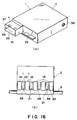
- Figure 16(a) is a perspective view of the recording means shown in Figure 15, and Figure 16(b) is a plan view of the bottom of the carriage shown in Figure 15.
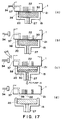
- Figures 17(a), 17(b), 17(c) and 17(d) are schematic sectional drawings, depicting the absorbency recovery operation in the fifth embodiment of the present invention.
- Figure 18 is a schematic sectional drawing, presenting a preferable positional arrangement of the cap leaking means in the fifth embodiment of the present invention.
- Figure 19 is a schematic perspective view of the recording means in the sixth embodiment of the present invention.
- Figures 20(a), 20(b), 20(c) and 20(d) are schematic sectional drawings, describing the absorbency recovery operation in a conventional ink jet recording apparatus.
- Figure 21 is a schematic perspective view of the ink jet recording apparatus in accordance with the present invention, depicting the essential structure of the seventh embodiment of the present invention.
- Figure 22 is a schematic drawing, showing the moving range of the carriage in the ninth embodiment of the present invention.
- Figures 23(a), 23(b) and 23(c) are drawings presenting an idealistic condition of the ink jet recording.
- Figures 24(a), 24(b) and 24(c) are drawings presenting an actual condition of the ink jet recording.
- Figures 25(a), 25(b) and 25(c) are drawings presenting an actual condition of the ink jet recording in the fine mode.
- Figures 26(a), 26(b) and 26(c) present magnified appearances of a staggered pattern and a reversely staggered pattern.
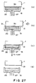
- Figure 27 illustrates a device according to a first embodiment of the present invention.
- FIG. 1 is a schematic perspective view of an ink jet recording apparatus according to the present invention, showing the essential structure of the preferred embodiment of the present invention.
- two or more (four) exchangeable head cartridges 1A, 1B, 1C and 1D are mounted on the carriage 2.
- Each of the head cartridges 1A to 1D has an ink container, at the top, and a recording head (ink ejecting member), at the bottom.
- the recording means comprises the head cartridges containing a combination unit of the recording head and ink container.
- Each of the head cartridges 1A to 1D also have a connector for receiving signals to drive the recording head, or the like.
- a recording means 1 (recording head 1, or head cartridge 1) refers to all of the recording means 1A to 1D or any given one of them.
- Each of the multiple head cartridges 1 effects recording using a different color
- its ink container contains one of the inks of a different color, for example, black, cyan, magenta, or yellow.
- the exchangeable recording means 1 is mounted on a carriage 2 through a positioning step, and the carriage 2 has a connector holder (electrically connecting member) for transmitting driving signals or the like to the recording means 1, through the aforementioned connector.
- the carriage 2 is supported by a guide shaft 3 place in the main structure of the apparatus, extending in the primary scanning direction to guide the forward or backward movement of the carriage 2.
- the carriage 2 is driven by a primary scanning motor 4, through a motor pulley 5, follower puller 6, and a timing belt 7, to control its position and movement.
- a recording material 8 such as printing paper or thin plastic film is held between two pairs of conveyer rollers 9 and 10, and 11 and 12, and is conveyed (paper feed) passing through a position (recording position) facing the ejection outlet surface of the recording 1, by the rotation of these conveyer rollers.
- the recording 8 is supported from behind by a platen (unshown), so that it can offer a flat recording surface at the recording position.
- the head cartridge 1 on the carriage 2 is held in such a manner that its ejection outlet surface protrudes downward from the carriage 2, and also, the ejection outlet surface remains parallel to the surface of the portion of the recording material 8 passing between two pairs of rollers.
- the aforementioned recording head (recording means) 1 is an ink jet recording means which comprises electrothermal transducers and ejects the ink using the thermal energy. More particularly, the thermal energy generated by the electrothermal transducers is applied to the ink, which triggers film boiling in the ink, developing a bubble. The bubble causes pressure change as it grows or collapses, and this pressure change is used to eject the ink from an ejection orifice 22, effecting thereby recording.
- Figure 2 is a schematic partial view of the recording head 1, showing the structure of the ink ejecting portion (recording head portion) thereof.
- a predetermined gap for example, 0.5 to 2.0 mm
- two or more ejection orifices 22 are formed with a predetermined pitch.
- a common liquid chamber 23 and each of the ejection orifices are independently connected with a liquid passage 24, and on the bottom wall surface of the liquid passage 24, an electrothermal transducer (exothermal resistor or the like) 25 is placed.
- a predetermined number of the recording heads 1 are arranged on the carriage 2 in such a manner that the ejection orifices 22 are aligned in the direction perpendicular to the scanning direction of the carriage 2.
- the electrothermal transducer 25 is driven (power is supplied) in response to the image signals or ejection signals to trigger film boiling in the ink within the liquid passage 24, and the pressure generated under this film boiling condition is used to eject the ink from the ejection orifices.
- a recovery system unit 14 which comprises a cap unit and a pump unit.
- the cap unit comprises two or more (four in this embodiment) caps 15, each being placed to face one of the ink ejecting portions 13 (recording head) of the head cartridge 1, and the pump unit 16 is individually connected to each of the caps 15, with a tube 27 or the like.
- the cap unit (or each of caps 15) can be vertically moved in synchronization with the approaching or departing movement of the carriage 2, so that when the carriage 2 is at the home position, each of the caps 15 can be tightly placed on one of the ejection outlet surfaces 21 of the recording head, sealing (capping) thereby the ejection orifice 22.
- This capping prevents the ink evaporation from the ejection orifice, preventing in turn the ink viscosity increase or solidified ink adhesion within the ejection orifice, and ultimately, preventing the occurrence of a faulty ejection.
- the recovery system unit 14 comprises a blade 18 being held by a blade holder 17 at a location between the cap and the recording material conveying member.
- the blade 18 serves as a wiping member formed of elastic material such as rubber, and wipes clean the ejection outlet surface 21 in coordination with the movement of the carriage 2.
- the blade 18 is set at a projecting position (wiping position) or a retracted position (wiping position) as the blade holder 17 is moved up or down by a blade moving mechanism (unshown) being driven by the movement of the carriage 2.
- a blade moving mechanism (unshown) being driven by the movement of the carriage 2.
- the wiping operation by the bladc 18 is carried out only when the carriage 2 is moving from the left side (recovery unit 14 side) to the right side of Figure 1.
- the blade 18 is located between the capping unit 15 and the recording material conveying system. That is, if the ejection outlet surface 21 is wiped when the carriage 2 moves from the right to the left in the figure, there is a possibility that the elasticity of the blade 18 may throw the wiped ink toward the recording material conveying system and the thrown ink may be splashed on the recording material 8 and soil it. If there is no possibility for such a problem, the wiping operation may be carried out in both directions.
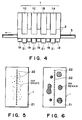
- Figure 3 is a plan view of the carriage 2, as seen from the bottom, and Figure 4 is a front view of the carriage 2.
- the ink absorbing members 19 (total of five) are fixed on the bottom surface of the carriage 2, in such a manner as to sandwich the ejection outlet surfaces 21 of the recording heads, in other words, with the appearance of one on each side of the ejection outlet surfaces of the respective recording heads 1 as shown in the drawings.
- These ink absorbing members 19 serve as cleaning means for cleaning the blade 18, and are made of ink corrosion-resistant, highly ink-absorbent, porous material.
- the ink absorbing members 19 are possitioned slightly below the ejection outlet surfaces 21 so that they do not rub against the recording material 8 during the recording operation.
- the gap between the ejection outlet surface 21 of the recording head 1 and the recording material 8 is minimized so as to minimize the landing error of the ink droplet, which in turn improves the image quality.
- the recording material 8 absorbs the ink, the water content becomes quite different between the surface where the ink is absorbed and the reverse side, and between the areas where the ink is absorbed and not absorbed. This difference in the water content causes uneven expansion and contraction of the recording material 8, which sometimes produce a swelling pattern called cockling.
- the gap between the recording head 1 and recording material 8 is set at the minimum width, within a range in which both do not touch each other even when deformation such as cockling is present on the recording paper.
- the aforementioned ink absorbing member 19 provided on the bottom surface of the carriage 2 for cleaning the blade is positioned slightly recessed below the recording head 1 which protrudes downward from the carriage 2. Further, the ink absorbing member 19 swells by absorbing the ink, and in consideration of the amount of this swelling, it is recessed from the recording head 1 by approximately 0.5 mm.
- Figure 5 is a schematic front view of the recording head 1, showing the ejection outlet surface 21 in a wet condition after the image recording.
- Figure 6 is a schematic front view of the recording head 1, showing the ejection outlet surface 21 to which the ink is adhering after the absorbency recovery operation.
- the ejection outlet surface 21 of the recording head 1 gets wet and looks as shown in Figure 21.
- the ink ejection is affected, triggering such problematic phenomenons that the ink is ejected in the unintended direction (shift), that the ink droplet is not ejected (no ejection), or the like.
- the absorbency recovery operation makes the ink adhere to the ejection outlet surface 21, as shown in Figure 6, and in this case, the amount of the adhering ink is more than in the case of just getting wet by the recording operation. Therefore, the ejection outlet surface 21 must be wiped (cleaned by wiping) by the blade 18 after the absorbency recovery operation, or with predetermined intervals (before the faulty ejection is triggered).
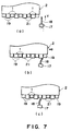
- Figure 7 schematically describes the wiping operation of this embodiment.
- the wiping operation of this embodiment is carried out only when needed, and while the carriage 2 is moved from the home position side (left side in Figure 7) to the recording material conveying system side (right side in Figure 7).
- Figure 7(a) shows the condition just before the wiping operation begins, and at this time, the blade 18 is elevated in the arrow Y direction, from the waiting position to a position (wiping position) where the blade 18 enters the passage of the recording head by the optimum amount for wiping the recording head 1, and is stopped there.
- the carriage 2 carrying the recording head 1 is horizontally moved from left to right, whereby the blade 18 altermately touches each of the ink absorbing members 19 fixed on the bottom of the carriage 2 and each of the ejection outlet surfaces 21 of the recording head 1 protruding from the carriage 2 and wipes away the foreign matter such as the ink adhering to the ejection outlet surface 21.
- the blade 18 is moved in the direction opposite to the arrow Y direction (lowered) to the retracted position where it waits.
- the ink absorbing members 19 for blade cleaning are positioned on both sides of each of the recording head 1, and therefore, the ink wiped off from each of the ejection outlet surfaces 21 is sequentially absorbed by the ink absorbing member 19, reducing constantly the amount of the ink left behind on the blade 18 to a minimum. This can prevent color mixing which may occur when the ejection outlet surface 21 of next recording head 1 is wiped.
- the ink absorbing capacity of the ink absorbing member 19 is limited, and therefore, when the amount of the ink adhering to the ejection outlet surface 21 is large, there is a possibility that the ink cannot be sufficiently absorbed.
- Figure 27 is a schematic sectional view of the cap and its surrounding area of the ink jet recording apparatus according to the present invention, depicting the ink sucking operation of the first embodiment.
- a cap 15 is made of rigid material, and comes in contact with the ejection outlet surface 21 in a manner to seal the surface it covers.
- the concavity of the cap 15 is occupied by a porous ink absorbing member 20, which fills the cavity almost to the rim so that it is places close to the ejection outlet surface 21 during the capping operation, as shown in Figure 27(a).
- An area 30 hatched in a higher density represents the ink sucked out of the ejection orifice (or sucked into the cavity).
- the cap 15 is made to airtightly contact the ejection outlet surface 21, and then, the suction pump 16 ( Figure 1) is started to generate the negative pressure in the cap 15, through the tube 27, whereby the ink is sucked from the ejection outlet surface 21. Then, the suction pump 16 is stopped.
- Figure 27(a) shows the positional relation between the cap 15 and the ejection outlet surface 21 immediately after the suction pump 16 is stopped. In this state, the negative pressure within the suction pump 16 will have been almost canceled by sucking out a give amount of the ink. In other words, the negative pressure will have sufficiently diminished without reaching a point at which the meniscus of the ejection orifice 22 begins to hold.
- the concavity of the cap 15 is almost entirely filled with the ink, in other words, the ink absorbing member 20 is saturated with the ink, having almost no absorbency. If the cap is separated in this condition, a large amount of the ink will be left on the ejection outlet surface 21 as shown in Figure 18. Therefore, in this embodiment, the carriage 2 is slightly displaced to the right in the drawing to create a gap 31 between the carriage 2 and ejection outlet surface 22, which serves as a micro vent at the interface of two components. The amount of the slight displacement of the carriage 2 for this purpose is determined to be as small as possible while allowing the seal to be broken between the cap 15 and ejection outlet surface 21.
- the term, "interface,” in the above statements means the contact surface where the cap 15 meets the ejection outlet surface 21 when the cap 15 covers the ejection orifice 22.
- a means for forming the gap that is, a gap forming means, a means for giving vernier movement, or the like is used to move the carriage 2.
- Figure 27(b) shows the condition of the concavity of the cap 15 immediately after the carriage is slight displaced from the location shown in Figure 27(a).
- the suction pump 16 Figure 1
- Figure 27(c) The state of the concavity of the cap 15 after the suction pump 16 is restarted is shown.
- the cap 15 has a leak (is open), and therefore, only the ink within the cap 15 (the ink retained in the ink absorbing member 20 in the drawing) is sucked by the restarted suction pump 16 through the tube 27, as shown in Figure 27(c), whereby the porous ink absorbing member 20 in the cap 15 recovers its ink absorbing capacity.
- the carriage 2 is returned to the previous position, that is, the position shown in Figure 27(a), where the ink absorbing member 20 with sufficiently recovered ink absorbing capacity is once again placed close to the entire area of the ejection outlet surface 20, reducing further the residual ink on the ejection outlet surface 21.
- FIG 27(d) shows the state after the cap is separated.
- the sucking operation by the suction pump 16 is stopped as soon as the sufficient amount of the ink is sucked from the ink absorbing member 20.
- the absorbency recovery operation is completed, leaving hardly the ink on the ejection outlet surface 21, as shown in Figure 27(d).
- the cap 15 is preferred not to be as rigid as the rigid cap shown in Figure 27, but to be made of elastic material, and if not, at least its contact surface (sealing surface) of the cap which comes in contact with the carriage 2 is preferred to be made of elastic material.
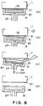
- Figure 8 shows a modified version of the cap of the first embodiment. This cap is entirely made of the elastic material.
- Figure 8 is a schematic sectional view of a cap made entirely of the elastic material, depicting another operation for sucking the ink.
- the operational stages shown by Figures 8(a), 8(b), 8(c), and 8(d) correspond to those shown by Figure 27(a), 27(b), 27(c), and 27(d), respectively.
- the main difference between Figure 8 and Figure 27 is in the slight displacement of the carriage 2 shown in Figure 8(b) and 8(c). Since the cap is deformable in this modification, the amount of the carriage displacement necessary for creating the cap between the cap and the ejection outlet surface 21 has only to be sufficient for deforming the cap itself, which gibes another reason why the elastic cap is preferable to the rigid one.
- Figure 9 shows another cap arrangement in which two or more caps are provided for a corresponding number of recording caps; Figure 9(a) showing the operational stage in which the caps are squarely on, and Figure 9(b) showing the stage in which the caps has been slightly displaced, wherein the states in Figure 9(a) and 9(b) correspond to those in Figures 27(a) and 27(b), and Figures 8(a) and 8(b).
- each recording head 1 is provided with its own cap 15, but two or more recording heads may be covered with a single cap.
- the amount of the slight displacement of the carriage 2 for shifting the cap 15 during the absorbency recovery operation was 0.4 mm.
- the temperature was set at 35 °C, and the humidity was set at 80% to 90%, being hot and humid.
- a sever environmental condition was set in which the amount of ejected ink was large, more ink adhering to the ejection outlet surface 21, and in addition, the ink was difficult to dry.
- the recording was made at a recording ratio of 100%, that is, solid black recording, increasing thereby the amount of adhering ink to the maximum. While 5000 pieces of A4 size recording material were run for the endurance test, no faulty ejection such as shifting or no ejection was observed. Another endurance test was conducted for comparison, in which the cap leak (opening by slight movement of the carriage) sequence was eliminated during the absorbency recovery operation. During this test, the faulty ejections or color mixing occurred after 1000 pieces or so were recorded. These tests proved that the service life of the ink jet recording apparatus comprising the blade 18 and blade cleaner 19 could be enormous improved in terms of sheet counts, by providing a means for creating the cap leak and sucking the ink within the concavity of the cap.
- recording heads 1 heads cartridges as shown in Figure 9 are used for color recording, but the number of the recording head is not limited to four. It may be one or other number beside one.
- This embodiment also solves a problem peculiar to the color recording, that is, the color mixing, and therefore, it is extremely effective when applied to the color recording apparatus.
- the slight displacement of the carriage 2 is in the primary scanning direction, but the direction of the slight displacement is not limited to the primary scanning direction. It may be in the secondary scanning direction (paper feed direction).
- the slight displacement is in the primary scanning direction, an existing means or structure can be utilized with a simple modification in the control method or the like. Therefore, the primary scanning direction is preferable to other directions, in teams of size reduction or mechanical simplification.
- the cap itself may be moved vertically, horizontally, or diagonally, instead of slightly displacing the carriage 2.
- the slight movement of the carriage 2 in the primary scanning direction is also preferable to this cap moving setup, just as it is preferable to the movement in the direction other than the primary scanning direction.
- each cap may be moved in the different direction.
- the same direction is preferable also in this modified version, in terms of the size reduction and simplification of the apparatus.
- FIG 10 is a schematic view of the cap and the ejection outlet surface 21 of the ink recording apparatus according to the present invention, describing the absorbency recovery operation of the second embodiment of the present invention.
- the airtight contact between the cap 15 and the ejection outlet surface 21 is caused to leak by pulling a portion of the cap 15, and thereby, deforming the cap 15 which is formed of the elastic material.
- a leak causing lever 32 is provided on the cap 15.
- the leak lever 32 is moved in the arrow A direction with a predetermined timing. While the cap 15 is sealing the surface of the ejection outlet surface 21, no force is imparted on the leak lever 32 to move it in the arrow A direction.
- the structure in the other portion of this embodiment is substantially the same as the first embodiment shown in Figures 1 to 9, and 27.
- Figure 11 is a schematic drawing showing a partially modified version of the second embodiment presented in Figure 10.
- Figure 11(a) shows the state in which the cap is sealing the ejection outlet surface 21, had
- Figure 11(b) shows the state in which the leak is established between the cap concavity and the atmosphere.
- the leak lever 32 is moved in the arrow A direction, that is, pulled, but in the case of the structure shown in Figure 11, the leak lever 32 is moved in the opposite direction (in the arrow B direction), that is, pushed.
- the ink is sucked from the ejection orifices 22 while the cap is sealing the ejection outlet surface 21 as shown in Figure 11(a).
- the leak lever 32 is moved in the arrow B direction as shown in Figure 11(b), whereby a portion of the cap 15 is pushed to deform the cap 15. As a result, the leak is established between the concavity of the cap 15 and the atmosphere. Meanwhile, the suction is continued by the operation of the suction pump 16 ( Figure 1) under the condition as shown in Figure 11(b), whereby the almost entire residual ink on the ejection outlet surface 21 is eliminated as it is in the first embodiment of the present invention.
- Figure 12 is a schematic view of the cap 15 and the ejection outlet surface 21 of the ink jet recording apparatus according to the present invention, describing the absorbency recovery operation in the third embodiment of the present invention.
- Figure 12(a) shows the state in which the cap 15 is apart from the ejection outlet surface 21;
- Figure 12(b) shows the state in which the cap 15 is sealing the ejection outlet surface 21;
- Figure 12(c) shows the state in which the leak is established by slightly displacing the carriage 2.
- the ejection outlet surface 21 of the recording head 1 and the contact surface of the cap 15 are slanted with reference to the direction in which the carriage 2 is slightly displaced (to the right in Figure 12).
- the angle of the contact surface of the cap 15 is matched with that of the ejection outlet surface 21.
- the ejection orifices 22 are sealed.
- the cap 15 of this embodiment may be made of either the rigid material or the elastic material, as described in the first embodiment. However, the elastic material is preferable in consideration of the airtight contact to be established between the cap 15 and the ejection outlet surface 21.
- the cap 15 is advanced (or elevated) from a retracted (lowered) position shown in Figure 12(a) to seal the ejection outlet surface 21 as shown in Figure 12(b). Then, after the airtight contact is established, the suction pump 16 ( Figure 1) is operated to suction the ink out of the ejection orifices 22 while maintaining the airtightness.
- the carriage 2 is slightly displaced to the right as shown in Figure 12(c), whereby the leak is established between the concavity of the cap 15 and the atmosphere.
- the other structures in this embodiment are practically the same as those in the first embodiment shown in FIgure 1 to 9.
- the ink is sucked out while the cap 15 is sealing the ejection outlet surface 21 as shown in Figure 12(b), and then, the carriage 2 is slightly displaced to the right of the figure.
- This movement deforms the cap 15 as shown in Figure 12(c), whereby the gap 31 is created between the cap 15 and the ejection outlet surface 21, establishing the leak between the concavity of the cap 15 and the atmosphere.
- the ink is sucked out by operating the suction pump 16 ( Figure 1) under the leaking condition shown in FIgure 12(c), whereby almost all of the residual ink on the ejection outlet surface 21 is eliminated as it is in the first embodiment.
- the ejection outlet surface 21 and the contact surface of the cap 15 are angled with reference to the direction in which the carriage 2 is slightly displaced, which offers such an advantage that it takes less displacement of the carriage 2 than the first embodiment, to create the gap between the ejection outlet surface 21 and the cap, in other words, it is easier to create the gap.
- Figure 13 shows a modified version of the third embodiment.
- the cap 15 is formed of the elastic material and the angle of its sealing surface is matched with the angle of the ejection outlet surface 21.
- the angle of the sealing surface of the cap 15 is slightly different from that of the ejection outlet surface 21.
- Figure 13(a) shows the state in which the cap is off the ejection outlet surface 21, and the direction in which the cap 15 is elevated
- Figure 13(b) shows the state in which the cap 15 is sealing the ejection outlet surface 21 after it is elevated in the arrow direction in Figure 12(a)
- Figure 13(c) shows the state in which the leak has been established either by slightly lowering the cap 15 in the arrow Y direction or by slightly moving the ejection outlet surface 21 in the arrow X direction.
- Figure 14 shows the fourth embodiment, in which a unique capping method is taken.
- the recording head 1 mounted on the carriage 2 has not reached the capping position; in Figure 14(b), the carriage 2 has reached the capping position and the capping has been completed; and in Figure 14(c), the carriage 2 is being slightly displaced from the capping position, establishing the leak.
- a reference numeral in Figure 14(a) designates a cap holder which is rotatable about an axis 28a. When the ejection outlet surface 21 is away from the cap as shown in Figure 14(a), the cap 15 is held at an angle.
- the cap 15 comes in contact with the ejection outlet surface 21, whereby it is rotated in the counterclockwise direction while remaining in contact with the ejection outlet surface 21, and reaches the capping position as shown in Figure 14(b).
- the ink is sucked from the ejection orifices 22 by operating the suction pump 16 connected to the cap 15 under the condition shown in Figure 14(b).
- the carriage 2 When the negative pressure within the cap 15 is almost entirely canceled after a certain amount of the ink is sucked out, the carriage 2 is slightly displaced to the right of the figure, whereby the cap 15 is slightly rotated in the counterclockwise direction about the axis 28a of the cap holder 28, creating the gap between itself and the ejection outlet surface 21. Under this condition, the suction pump 16 is restarted, whereby almost all of the ink on the ejection outlet surface 21 and within the cap 15 can be removed.
- the cap 15 is rotated by the movement of the carriage 2.
- the cap may be directly driven in coordination with the movement of the carriage 2.
- the structure in this embodiment allows a better control of the deformation of cap 15 and the moving directions of the cap and the ejection outlet surface 21 during their slight movements, and therefore, it can more reliably control the leak.
- the wiping means 18 which wipes away the foreign matter adhering to the ejection outlet surface 21 as it moves, relative to the movement of the ejection outlet surface 21, while being pressed against the ejection outlet surface 21 of the recording head 1; the cleaning means 19 which is positioned next to the ejection outlet surface 21, with its upper surface being substantially level with the ejection outlet surface 21, cleaning thereby the wiping means 18 as it moves, relative to the movement of the wiping means 18, while being pressed against the wiping means 18; and the sucking means 16 for forcefully sucking the ink from the ejection orifices 22, the airtight contact established by the cap 15 is caused to break, in other words, the cap 15 is caused to leak while the ink is sucked out, whereby the residual ink on the ejection outlet surface 21 is reduced to the absolute minimum after the absorbency recovery operation.
- the ink jet recording apparatus can sustain the ink ejection performance, offering thereby excellent image quality, over a long period. Further, such a nuisance that the direction of ink ejection is shifted by the waste ink adhering to the ejection outlet surface 21, degrading thereby the image quality, in other words, the nuisance originating from using liquid ink as the recording agent, is prevented over a long period. Therefore, it is possible to provide an ink jet recording apparatus capable of sustaining the performance to produce an excellent height quality image.
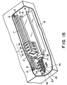
- FIG 15 is a schematic perspective view of an ink jet recording apparatus to which the present invention has been applied, depicting the essential structure of the fifth embodiment of the present invention.
- an air passage communicating with (opening to) the ejection outlet surface 21 is provided in each of the recording heads 1.
- a valve 4 for opening or closing the air passage (at the other end of the passage) is provided; one for each of the recording heads 1, that is, a total of four are provided, as shown in Figure 15.
- the valve 4 is driven with a predetermined timing by an unshown cam mechanism to be placed in contact with (closing) or to be moved away (opening) from the opening of the air passage of the recording head 1, that is, the opening opposite to the ejection outlet surface 21.
- an unshown cam mechanism to be placed in contact with (closing) or to be moved away (opening) from the opening of the air passage of the recording head 1, that is, the opening opposite to the ejection outlet surface 21.
- Figure 16 show the recording head 1 (head cartridge) and the carriage 2 of the recording apparatus shown in Figure 15;
- Figure 16(a) is a perspective view of the recording head 1
- Figure 16(b) is a plan view of the carriage 2, as soon from the bottom, which is correspondent with Figure 3.
- the recording head 1 is an exchangeable combination head comprising a recording head member H and an ink container T.
- One of the end surfaces of the recording head H serves as the ejection outlet surface 21 where two or more ejection orifices 22 are present.
- a reference numeral 35 designates a connector to receive signals for driving the recording head 1
- a reference numeral 36 designates an air vent of the ink container T.
- the recording head 1 is provided with an air passage 37 communicating with (opening at) the ejection outlet surface 21.
- the cross-sectional area of this air passage 37 is preferred to be larger than that of the ejection orifice 22, so that flow resistance becomes small enough to prevent the ink from remaining in the air passage 37.
- the ink absorbing members 19 as the cleaning means (blade cleaner) for cleaning the blade 18 are fixed in such a manner as to sandwich the ejection outlet surface 21 of the recording head 1, in the same manner as is shown in Figure 3.
- the air passage 37 opens at the ejection outlet surface 21, and the location of this opening 38 of the air passage 37 is selected so as for the opening 38 to fall within the boundary of the cap 15 when the cap is sealing the ejection outlet surface 21.
- the structure of this embodiments is different from those in the first embodiment shown in Figure 1 to 9, in that the valve 34 and air passage 37 are provided, but otherwise, it has practically the same structure. Therefore, the corresponding components are designated by the same reference codes, and their detailed descriptions are omitted.
- FIG 17 is a schematic drawing for describing the ink sucking operation in this embodiment (fifth embodiment).
- the porous ink absorbing member 20 is placed within the concavity of the cap 15, filling the cap 15 almost to the rim so that the ink absorbing member 20 will be positioned extremely close to the ejection outlet surface 21 when the cap 15 is airtightly placed on the ejection outlet surface 21.
- the densely hatched area 30 represents the ink sucked from the ejection orifice 22.
- the air passage 37 communicating with the ejection outlet surface 21 is closed at the shutoff valve 34.
- the cap 15 seals the ejection outlet surface 21.
- Figure 17(a) shows the state of this moment.
- the negative pressure which is still present after the suction pump 16 is stopped, has been almost completely canceled as a given amount of the ink is sucked out, in other words, the negative pressure has been reduced to a point where the meniscus at the ejection orifice 22 begins to hold.
- the concavity of the cap 15 is connected to the atmosphere through the air passage 37, that is, the cap 15 is under the leak (open) condition, and since the flow resistance of the air passage 37 is smaller than that of the ejection orifice 22, only the ink within the cap 15 is sucked by the suction pump 16 through the tube 27, with no ink being sucked out of the ejection orifices 22, whereby the porous ink absorbing member 20 placed in the cap 15 recovers its full ink absorbing capacity. Further, this renewed porous ink absorbing member 20 is still placed so close to the ejection outlet surface 21 that almost all of the ink left on the ejection outlet surface 21 is absorbed by this ink absorbing member 20, boasting now its full ink absorbing capacity.
- the cap 15 After even the ink to be otherwise left on the ejection outlet surface 21 is absorbed in the ink absorbing member 20, and then, is sucked away by the suction pump 16, the cap 15 is separated from the ejection outlet surface 21. Therefore, the absorbency recovery operation is completed leaving hardly any ink on the ejection outlet surface 21.
- the second sucking operation by the suction pump 16 is stopped after the ink within the ink absorbing member 20 is sufficiently emptied by sucking. Because of the described structure and operation, the absorbency recovery operations is completed, leaving hardly any ink on the ejection outlet surface 21.
- Figure 18 is a schematic drawing for describing a preferable positional relation between the air passage 37 of the recording head 1 and the suction opening 39 (opening leading to the tube 27) of the cap 15. From the standpoint of the performance to suck effectively the ink throughout the concavity of the cap 15, it is preferable for the air passage 37 and the suction opening 39 to be positioned apart from each other as for as possible, as shown in Figure 18.
- the air passage 37 also remains closed by the shutoff valve 34 to prevent the ink from evaporating, so that the ink does not increase its viscosity at the ejection orifices 22; does no dry up there; and does not dry up and stick there. Further, if the air passage is located close to the ejection orifices 22, the ink can be sucked from the proximity of the ejection orifices 22, which can more reliably prevent the ink from adhering to the ejection outlet surface 21.
- the amount of the slight displacement of the carriage 2 for shifting the cap 15 during the absorbency recovery operation was 0.4 mm.
- the temperature was set at 35 °C, and the humidity was set at 80 % to 90 %, being hot and humid.
- a sever environmental condition was set in which the amount of ejected ink was large, with more ink adhering to the ejection outlet surface 21, and in addition, the ink was difficult to dry.
- the recording was made at a recording ratio of 100 %, that is, a solid black recording, increasing thereby the amount of adhering ink to the maximum. While 5000 pieces of A4 size recording material were fed for the endurance test, no faulty ejection such as shifting or no ejection was observed. Another endurance test was conducted for comparison, in which the air passage 37 of the recording head 1 and the shutoff valve 34 were eliminated. During this comparison test, the faulty ejections or color mixing occurred after 1000 pieces or so were recorded. These tests proved that the service life of the ink jet recording apparatus comprising the blade 18 and blade cleaner 19 could be enormous improved in terms of sheet count, by providing the recording head 1 with the air passage 37 and the shutoff valve 34.
- recording head 1 head cartridges
- the number of the recording head is not limited to four. It may be one or another number beside one.
- This embodiment also solves a problem peculiar to the color recording, that is, the color mixing, and therefore, it is extremely effective when applied to a color recording apparatus.
- FIG 19 is a schematic perspective view of a recording head of an ink jet recording head according to the present invention, describing the sixth embodiment of the present invention.
- the air passage 37 opening at the ejection outlet surface 21 is provided at two locations, in other words, the opening 38 of the air passage 37 on the ejection outlet surface 21 is located at both ends of the column of the ejection orifices 22.
- the other structure of this embodiment is practically the same as the fifth embodiment shown in Figures 15 to 18. According to this embodiment, the ink left otherwise on the ejection outlet surface 21 during the absorbency recovery operation is almost entirely eliminated.
- the air passage 37 is provided at both ends of the ejection outlet surface 21, this embodiment offers not only the same effects as the aforementioned fourth embodiment, with an added air intake efficiency, but also other effects, such that even if one of the air passages 37 is clogged, the air can still be taken in through the other air passage 37, further assuring the removal of the ink.
- the air passage 37 of the recording head 1 may be provided at three or more locations, wherein the number or locational arrangement of the openings 38 with reference to the column of the ejection orifices 22 is not limited to the one shown in the drawing, and may be optionally determined.
- the wiping means 18 which wipes away the foreign matters adhering to the ejection outlet surface 21 as it moves, relative to the movement of the ejection outlet surface 21, while being pressed against the ejection outlet surface 21 of the recording head 1; the cleaning means 19 which is positioned next to the ejection outlet surface 21, with its upper surface being substantially level with the ejection outlet surface 21, cleaning thereby the wiping means 18 as it moves, relative to the movement of the wiping means 18, while being pressed against the wiping means 18; the sucking means 16 for forcefully sucking the ink from the ejection orifices 22; the air passage 37 communication with the ejection outlet surface 21 of the recording head 1; and the shutoff means 34 for opening or closing the air passage 37, the residual ink on the ejection outlet surface 21 is eliminated after the sucking operation for recovering the performance of the ejection outlet 21 of the recording head 1.
- the ink jet recording apparatus can sustain the ink ejection performance, offering thereby excellent image quality, over a long period. Further, such a nuisance that the direction of ink ejection is shifted by the waste ink adhering to the ejection outlet surface 21, degrading thereby he image quality, in other words, the nuisance originating from using liquid ink as the recording agent, is prevented over a long period. Therefore, it is possible to provide an ink jet recording apparatus capable of sustaining the performance to produce an excellent high quality image.
- the internal volume of the cap 15 can be reduced, in other words, the size of the cap 15 can be reduced, to match the small head cartridge 1, the amount of the ink to be sucked out can be minimized, reducing thereby the amount of the waste ink.
- FIG 21 is a schematic perspective view of an ink jet recording apparatus according to the present invention, describing the seventh embodiment of the present invention.
- two or more (four) exchangeable head cartridges 1A, 1B, 1C, and 1D are mounted on the carriage 2.
- Each of the head cartridges 1A to 1D has an ink container, at the top, and a recording head (ink ejecting member), at the bottom.
- the recording means (recording heads) 1A to 1D are the combination head cartridges in which the recording head and ink container are combined.
- the recording data are transmitted to the recording heads 1A to 1D, from the electrical circuit of the main assembly of the apparatus through a cable 51.
- the term, "recording means 1 (recording head or recording cartridge),” designates either all of the recording means 1A to 1D, or any one of them.
- the two or more recording heads 1 in this embodiment are devices for ejecting ink from two or more ejection orifices 22 to form micro dots on the recording material 8, comprising thereby images.
- Each of the ink ejecting members of the recording head 1 have the same structure as that in Figure 2.
- Ink of different color (or different density) is ejected from each of different recording heads 1, and the proper mixture of the ink droplets forms color images on the recording material 8.
- colors used in the different recording heads 1 for color recording they are such colors as black, cyan, magenta, and yellow.
- These exchangeable recording heads 1 are mounted on the carriage 2 to hold a specific positional relation. The color inks are ejected in the aforementioned order while the carriage 2 is moved in the primary scanning direction.
- each recording head 1 is positioned with a predetermined interval (P1) from the adjacent ones. Therefore, for instance, when solid green color is wanted, the recording of the yellow color is delayed by twice the aforementioned interval (2 x P1) after the recording of the cyan color begins, in other words, the solid yellow color is recorded on top of the solid cyan color.
- the carriage 2 movement is the primary scanning direction is controlled in response to the scanning speed and recording location of the carriage 2 deleted by a speed detecting means (unshown).
- the carriage 2 is driven by the carriage driving motor 5 through the timing belt, whereby the carriage 2 shuttles along the guide shaft 54 extended in the primary scanning direction of the carriage 2.
- recording is made in a horizontal line (belt) while the carriage 2 is moved in the primary scanning direction.
- unidirectional and bidirectional recordings There are two types in the horizontal recording; unidirectional and bidirectional recordings.
- recording is made only when the carriage 2 is moving from the home position set up on one side of the apparatus to the opposite side (forward movement), and is not made while the carriage 2 is returning to the home position. Therefore, the unidirectional recording can produce images of high precision.
- the bidirectional recording recording is made in both forward and backward directions, and therefore, it can record at high speed.
- a recovery unit 55 is located at a side location (left end in the drawing) which is within the moving range of the carriage 2, but is off the passageway of the recording material.
- This recovery unit 55 is provided for maintaining the performance of the recording head 1, or recovering the performance of the recording head 1 when the faulty ink ejection occurs.
- it has a cap unit 56.
- the cap 56 is pressed on the ejection outlet surface 21 to seal the ejection orifices 22, and it is used not only for recovering the performance for the recording head 1, but also for preventing the ink in the ejection orifices 22 from drying or the like, during the non-recording period. Therefore, the position where the carriage 2 (hence, recording unit 1) faces the performance recovery unit 55 is called the home position.
- the function of the recovery unit 55 during the actual recording operation is concretely described.
- the carriage is moved (while the recording head 1 is not capped), if the ink is not ejected from a certain ejection orifice 22 for a given period, the ink adhering around the ejection orifices 22 on the ejection outlet surface 21 dries up and sticks there.
- the ink ejection performance of this orifice declines, resulting in the inferior image quality.
- the ink is ejected with given intervals, in addition to being ejected in response to the recording data.
- Such an extra ink ejecting operation besides the ejection for actual recording is called preliminary ejection.
- ink catcher In order to prevent the recording material 8 or the interior of the apparatus from being soiled by the ink splash, and ink catcher must be provided, wherein the ink is ejected toward the ink catcher, with the recording head 1 directly facing the ink catcher.
- the recording material 8 is conveyed in the secondary scanning direction by a conveying member such as rubber rollers being driven by an unshown sheet feeding motor.
- the recording material 8 is fed from the side indicated by an arrow A.
- recording begins to be made on the recording material 8 by the recording head 1.
- the recording material 8 on which recording has been made is discharged in the direction indicated by an arrow B by a discharging mechanism comprising a sheet discharging roller 57 or the like.
- each of the recording heads 1 is supplied with one of the inks of different colors stored in different ink containers.
- Figures 23 and 24 are schematic drawings for depicting the dot formations for the fine mode of a recording system.
- Figures 23 and 24 show a case in which the recording head 1 has eight ejection orifices aligned straight.
- ink droplets 61 are ejected from the ejection orifices 22 of the recording head 1 toward the recording material 8.
- the ink droplets 61 composed of the same amount of the ink are ejected in the same direction, as shown in Figure 23(a), which constitutes an idealistic ejection.
- dots of an equal size are landed on precise locations of the recording material 8, as shown in Figure 23(b), whereby images are recorded with no uneven recording density over the entire recording material 8, as shown in Figure 23(c).
- Laid-Open Japanese Patent Application No. 107,975/1985 discloses the following method, which pertains to the monochrome recording head. The method is briefly described referring to Figures 25 and 26. In this method, the recording head 1 is made to scan the recording material 8 three times to finish recording the area shown in Figures 23 and 24. However, each horizontal half of the area, which corresponds to four dots width, is subjected to two scanning passes. In this case, the number of dots recorded by a single ejection orifice 22 during a single scan is half the number for the normal scanning, which corresponds to a half of the image data.
- every other data in a series of data is skipped during the first scanning pass, and the skipped data are used for inserting the rest of dots during the second scanning pass, to finish the horizontal half of the area, which correspond to four dots width.
- Such a recording system is called the fine recording system.
- the recording data are divided into two groups of data, one for the first scanning run and the other for the second scanning run, so that the corresponding dots are formed into a pattern capable of complementing itself between the first and second scanning runs, wherein, generally speaking, the image data are arranged (skipped) to create a dot pattern staggered both horizontally and vertically as shown in Figure 26.
- each of the horizontal halves (area corresponding to a unit of four ejection orifices) of the recording area which is ordinarily completed by a single scanning is completed by combination of the first scanning for recording the normal staggered pattern, and the second scanning for recording the reversal staggered pattern.
- Figure 26(a), 26(b) and 26(c) are drawings for describing how the recording of a given area is covered with the aforementioned normally and reversely staggered dot patterns, using a recording head 1 having the same number, that is, eight, of the ejection orifices 22 as the one shown in Figures 23 and 24.
- the staggered dot pattern is recorded using the bottom four ejection orifices 22 as shown in Figure 26(a).
- the reversely staggered dot pattern is recorded by the second scanning as shown in Figure 26(b).
- the staggered dot pattern is again recorded by the third scanning as shown in Figure 26(c).
- the staggered and reversely staggered dot patterns are alternately recorded while the recording material is advanced by the distance correspondent to the four ejection orifices, whereby the recording area correspondent to the four ejection orifices is completed by each scanning.
- the same recording area is covered by two different ejection orifices, and therefore, this system can produce high quality images with no recording density irregularity.
- the ink catcher for catching the ink ejected during the preliminary ejection is provided on both ends of the apparatus, one at the home position HP and the other at a position YP opposite to the home position across the apparatus, which are within the moving range of the carriage 2 and are off the passageway of the recording material 8.
- one of the ink catchers (the one on the left in the drawing) is the cap unit 56 itself of the performance recovery unit located at the home position HP, and the other is an ink catching member 58 disposed at the position YP, opposite to the home position.
- This ink catching member 58 is capable of absorbing and retaining the ink ejected during the preliminary ejection.
- the ink catching member 58 of this embodiment contains a porous ink absorbing member 59.
- the ink absorbing member 59 disposed in the ink catching member 58 is connected to a waste ink absorbing member provided within the main assembly of the apparatus, whereby the ink ejected during the preliminary ejection is led to the waste ink absorbing member, to be stored there.
- This ink absorbing member 59 may be of an exchangeable type.
- this ink catching means provided on the side opposite to the home position may be structured so that the ink ejected during the preliminary ejection is sucked out by the recovery pump (unshown) of the performance recovery unit provided on the home position side.
- the ink catching member is formed as a cap, and the ink absorbed by the absorbing member 59 and accumulating in it is sucked out by the recovery pump and sent to the waste ink absorbing member.
- the recording is made as the carriage 2 carrying two or more (four in this case) recording heads 1 is moved forward or backward in the primary scanning direction.
- the carriage 2 is allowed to move on in the same direction till it reaches the position for preliminary ejection in the same direction, where it faces the ink catching means and ejects the ink into it.
- the carriage 2 is allowed to move to the right end position YP, where it preliminarily ejects the ink into the ink catching means 58 and 59.
- the carriage 2 If the preliminary ejection timing arrives while the carriage 2 is moving to the left (backward scanning) in Figure 21, the carriage 2 is allowed to move to the home position HP, where it preliminarily ejects the ink into the cap 56, as the ink catching means, of the recovery unit 55.
- the ink catching means is provided at both ends of the recording apparatus (two locations), and when the preliminary ejection timing arrives, the carriage 2 is allowed to move in the same direction as it has been moving at the moment to reach the ink catching means, being in the same direction, where the ink is preliminarily ejected. Therefore, the ink is preliminarily ejected with most efficient timing, whereby the ink permeation difference between the recording lines caused by the difference in the elapsed time after the preliminary ejection can be minimized. Thus, the image quality can be improved while increasing the recording speed.
- the preliminary ejection is carried out each time the scanning direction of the carriage 2 is reversed.
- the preliminary ejection is carried out at the same time by four color recording heads 1A to 1D carried on the carriage 2 each time the scanning direction is reversed.
- the preliminary ejection, scanning reversal, and line feed are carried out with the same timing, whereby the horizontal streaks caused by the difference in the ink permeation time can be effectively prevented.
- the amount of the ink ejected per preliminary ejection may be smaller, compared to the seventh embodiment.
- one to three recording heads 1 out of four recording heads 1 are made to preliminarily eject the ink at the same time, in other words, one to three colors are preliminarily ejected at the same time, each time the scanning direction is reversed. Since the preliminary ejection is carried out each time the carriage 2 moves out of the recording range, one to three colors out of four colors may be ejected at the same time, and this procedure may be repeated with a predetermined intervals. For example, the black and cyan are preliminarily ejected during the forward scanning, that is, the first scanning, and the magenta and yellow are preliminarily ejected during the backward scanning.
- Another example is to eject the colors one at a time, that is, to eject the black during the first forward scanning, the cyan during the first backward scanning, the magenta during the second forward scanning, and the yellow during the second backward scanning.
- This sequence has an advantage of improved recording operation throughput.
- the carriage 2 When the ink is preliminarily ejected into the ink catching means facing the recording heads (cap 56, ink catching member 58, or the like), the carriage 2 must be moved, with high positional accuracy, to the position where the recording heads is to face the ink catching means.
- a substantial run-up distance is required for the carriage 2. Accordingly, the moving range of the carriage 2 must be extended, whereby it becomes possible for the overall recording time to be prolonged.
- each color ink is preliminarily ejected one at a time into one of the two ink catching members located separately at the opposite ends of the moving range of the carriage 2, whereby the moving range of the carriage 2 can be shortened to improve the throughput.
- the throughput is improved by adopting such a sequence that the recording heads 1A and 1B mounted on the right side of the carriage 2 are made to preliminarily eject the ink at the same time or separately, at the YP position, and the recording heads 1C and 1D mounted on the left side of the carriage 2 are made to preliminarily eject the ink at the same time or separately, at the home position HP.
- Figure 22 is a schematic drawing showing the moving range of the carriage 2 in the ink jet recording apparatus which adopts such a sequence (ninth embodiment).
- a range indicated by a solid arrow mark E designates the moving range of the carriage in this embodiment
- a range indicated by a dotted arrow mark F designates the moving range of the carriage when the preliminary ejection is carried out at the same time for all four colors and in both scanning directions.
- the sheet passageway range G where the recording material 8 is passed is taken wider than the recording range H of the recording head 1.
- the recording apparatus size can be reduced and the throughtput can be improved.
- the recording apparatus comprises two or more recording heads, and the recording is bidirectionally made
- the preliminary ejection of each recording head is separately carried out.
- the ink is preliminarily ejected only from the recording heads being not in use for a predetermined period.
- the preliminary ejection is carried out by the recording heads having not been in use for the predetermined period, based on the recording data. Therefore, it is possible to avoid unnecessary ink consumption, by adopting this first sequence.
- the preliminary ejection is carried out for the ejection orifices having not been in use for a predetermined period. It is not always that all of the ejection orifices of the recording head 1 are used during the recording operation. Therefore, as the recording operation continues, ejection performance difference occurs between the frequently used ejection orifices and the infrequently used ejection orifices. This phenomenon is thought to be caused by the ink conformability difference between the above described two groups of ejection orifices.
- the ink in this ejection orifice increase its viscosity, and increased ink viscosity deteriorates the ink ejection performance.
- the ink is sucked out by the ink ejection performance recovery unit 55.
- the ink is sucked out even from the ejection orifices which are normally in use during the recording operation. Therefore, as the sucking count increase, the ink consumption increases, in other words, increases wasteful ink consumption.
- ink is preliminarily ejected from the infrequently used ejection orifice than the frequently used one, during the recording operation, whereby the performance deterioration of the infrequently used ejection orifice caused by the increased ink viscosity or the like can be prevented.
- the ink is ejected at a rate of 300 dots per frequently used ejection orifice during the preliminary ejection, the ink is ejected at a rate of 600 dots per ejection orifice from the infrequently used ejection orifice.
- the ink ejection performance of the recording head can be sustained at the most excellent level, without increasing the amount of the wasteful ink consumption.
- the discrimination between the frequently used ejection orifice and the infrequently used ejection orifice it is made by counting the number of recording dots using a recording data buffer, or, if the number of ejection orifices to be used in known based on the types of recording mode (64 orifices are used in a recording mode A; only 48 ejection orifices are used in a recording mode B, and so on), the ejection orifice for which preliminary ejection count is increased is selected based on the aforementioned types of recording mode.
- the preliminary ejection catcher is provided at both ends of the recording apparatus, beyond the recording range, and the preliminary ejection is carried out each time the scanning direction of the carriage 2 is reversed during the bidirectional recording operation, whereby it is possible for the preliminary ejection during the recording operation to be carried out as needed outside the recording range each time the scanning direction of the carriage 2 is reversed. Therefore, the throughput of the bidirectional recording can be improved. Further, the recording timing shift caused by the preliminary ejection during the actual recording operation can be eliminated, and therefore, it is possible to prevent the image deterioration such as the horizontal streaks. Lastly, the preliminary ejection count for the infrequently used ejection orifice is increased compared to the frequently used one, and therefore, it is possible to prevent the deterioration of the ink ejection performance while reducing the amount of ink consumption.
- the description is referred to an exchangeable head cartridge as the recording means in which the recording head member and the ink container are combined.
- the present invention is equally applicable to a recording head comprising an independent recording head member and an independent ink container.
- the present invention is applicable regardless of the arrangement between the recording head member and the ink container, with the same effects.
- the descriptions were referred to a color recording apparatus comprising two or more recording heads for recording in different colors.
- the present invention is equally applicable to a recording apparatus comprising a single recording head, a gradation recording apparatus comprising two or more recording heads for recording in a single color while varying the density, or the like, in other words, the present invention is equally applicable regardless of the number of recording heads or the variety and density of the ink, with the same effects.
- the present invention is usable with any ink jet apparatus, such as those using electromechanical converter such as piezoelectric element, but is particularly suitably usable in an ink jet recording head and recording apparatus wherein thermal energy by an electrothermal transducer, laser beam or the like is used to cause a change of state of the ink to eject or discharge the ink. This is because the high density of the picture elements and the high resolution of the recording are possible.
- the typical structure and the operational principle are preferably the ones disclosed in U.S. Patent Nos. 4,723,129 and 4,740,796.
- the principle and structure are applicable to a so-called on-demand type recording system and a continuous type recording system.
- it is suitable for the on-demand type because the principle is such that at least one driving signal is applied to an electrothermal transducer disposed on a liquid (ink) retaining sheet or liquid passage, the driving signal being enough to provide such a quick temperature rise beyond a departure from nucleation boiling point, by which the thermal energy is provided by the electrothermal transducer to produce film boiling on the heating portion of the recording head, whereby a bubble can be formed in the liquid (ink) corresponding to each of the driving signals.
- the liquid (ink) is ejected through an ejection outlet to produce at least one droplet.
- the driving signal is preferably in the form of a pulse, because the development and contraction of the bubble can be effected instantaneously, and therefore, the liquid (ink) is ejected with quick response.
- the driving signal in the form of the pulse is preferably such as disclosed in U.S. Patents Nos. 4,463,359 and 4,345,262.
- the temperature increasing rate of the heating surface is preferably such as disclosed in U.S. Patent No. 4,313,124.
- the structure of the recording head may be as shown in U.S. Patent Nos. 4,558,333 and 4,459,600 wherein the heating portion is disposed at a bent portion, as well as the structure of the combination of the ejection outlet, liquid passage and the electrothermal transducer as disclosed in the above-mentioned patents.
- the present invention is effectively applicable to a so-called full-line type recording head having a length corresponding to the maximum recording width.
- a recording head may comprise a single recording head and plural recording head combined to cover the maximum width.
- the present invention is applicable to a serial type recording head wherein the recording head is fixed on the main assembly, to a replaceable chip type recording head which is connected electrically with the main apparatus and can be supplied with the ink when it is mounted in the main assembly, or to a cartridge type recording head having an integral ink container.
- the recording head mountable may be a single corresponding to a single color ink, or may be plural corresponding to the plurality of ink materials having different recording color or density.
- the present invention is effectively applicable to an apparatus having at least one of a monochromatic mode mainly with black, a multi-color mode with different color ink materials and/or a full-color mode using the mixture of the colors, which may be an integrally formed recording unit or a combination of plural recording heads.
- the ink has been liquid. It may be, however, an ink material which is solidified below the room temperature but liquefied at the room temperature. Since the ink is controlled within the temperature not lower than 30 °C and not higher than 70 °C to stabilize the viscosity of the ink to provide the stabilized ejection in usual recording apparatus of this type, the ink may be such that it is liquid within the temperature range when the recording signal is the present invention is applicable to other types of ink. In one of them, the temperature rise due to the thermal energy is positively prevented by consuming it for the state change of the ink from the solid state to the liquid state. Another ink material is solidified when it is left, to prevent the evaporation of the ink.
- the ink is liquefied, and the liquefied ink may be ejected.
- Another ink material may start to be solidified at the time when it reaches the recording material.
- the present invention is also applicable to such an ink material as is liquefied by the application of the thermal energy.
- the ink jet recording apparatus may be used as an output terminal of an information processing apparatus such as computer or the like, as a copying apparatus combined with an image reader or the like, or as a facsimile machine having information sending and receiving functions.
- an ink jet recording apparatus comprising: a carriage for carrying recording means for effecting recording by ejection of ink on a recording material; a cap for capping an ejection outlet of the recording means formed in an ejection side surface; sucking means for sucking the ink out through the ejection outlet while the cap is closely contacted to the ejection side surface; clearance forming means for forming a clearance at a part of close-contact portion between the ejection side surface and the cap by relative motion between the cap and the carriage.
- the ink deposited on the ejection side surface of the recording means is removed a much as possible, thus preventing contamination of the inside of the apparatus or the recording material, and preventing deterioration of the wiping means.
- the ink ejection of the recording means can be stabilized to permit satisfactory recording operation for long term.
- an ink jet recording apparatus comprising: a carriage for carrying recording means for effecting recording by ejection of ink on a recording material; a cap for capping an ejection outlet of the recording means formed in an ejection side surface; sucking means for sucking the ink out through the ejection outlet while the cap is closely contacted to the ejection side surface; an air communication opening, in the recording means, for communicating a space covered by the cap with an ambient air; and shut-off means for shutting off and opening the air communication opening.
- the ink can be removed from the ejection side surface of the recording means as much as possible, so that the contamination of the apparatus and the recording material is prevented, thus preventing deterioration of the wiping means.
- the ink ejection of the recording means can be stabilized, so that the satisfactory recording operation is possible for a long term.
- an ink jet recording apparatus in which the ink is ejected on a recording material from recording means moving in a main scan direction, wherein a plurality of recording means are used, and ink receptors are provided at opposite ends outside the recording material passage area, and the ink is ejected to the ink receptor through at least one recording means for each reversal of the main scan movement. Therefore, the reduction of throughput by the preliminary ejection during the recording, can be prevented, and production of lateral stripe due to the deviation of the recording timing can be prevented.
- a recording unit mountable to a carriage of an ink jet recording apparatus having a cap for capping an ejection outlet of the recording means to effect recording, comprising: an ejection side surface having an ejection outlet; an air communication opening having an end engageable with shut-off means of the ink jet recording apparatus and another end to be covered by the cap.
- the ink deposited on the ejection side surface of the recording means can be removed as much as possible, thus preventing contamination of the inside of the apparatus and the recording material, and therefore, preventing the deterioration of the performance of the wiping means.
- the ink ejection of the recording means is stabilized to permit satisfactory recording operation for a long term.
- a method of recovering an ink jet apparatus provided with a carriage capable of carrying recording means for effecting recording by ejection of ink on the recording material, comprising the steps of: capping an ejection side surface having an ejection outlet by a cap at least partly deformable; sucking the ink through the ejection outlet by sucking means while the cap being closely contacted to the ejection side surface; forming a clearance at least partly between the cap and the ejection side surface; operating the sucking means while the clearance is present.
- the ink deposited on the ejection side surface of the recording means is removed as much as possible, thus preventing contamination of the inside of the apparatus and the recording material, thus preventing deterioration of the performance of the wiping means.
- the ink ejection of the recording means is stabilized to permit satisfactory recording operation for long term.
- a method of recovering an ink jet recording apparatus having a carriage for carrying recording means for effecting recording by ejection of ink to a recording material comprising: capping with a cap an ejection outlet formed in an ejection side surface of the recording means; sucking the ink through the ejection outlet while the cap is closely contacted to the ejection side surface, and while an air communication opening provided in the recording means for communication of a space closed by the cap with an ambient air, is being in a closed state; and sucking an inside of the cap while the air communication opening is in an open state.
- the ink deposited on the ejection side surface of the recording means is removed as much as possible, thus preventing contamination of the inside of the apparatus and the recording material, and preventing deterioration of the performance of the wiping means.
- the ink ejection of the recording means is stabilized to permit satisfactory recording for the long term.
Landscapes
- Ink Jet (AREA)
Applications Claiming Priority (3)
| Application Number | Priority Date | Filing Date | Title |
|---|---|---|---|
| JP21836892 | 1992-07-24 | ||
| JP218368/92 | 1992-07-24 | ||
| JP04218368A JP3083409B2 (ja) | 1992-07-24 | 1992-07-24 | インクジェット記録装置および該記録装置の回復方法 |
Publications (3)
| Publication Number | Publication Date |
|---|---|
| EP0580437A2 true EP0580437A2 (fr) | 1994-01-26 |
| EP0580437A3 EP0580437A3 (fr) | 1995-05-03 |
| EP0580437B1 EP0580437B1 (fr) | 2000-01-12 |
Family
ID=16718803
Family Applications (1)
| Application Number | Title | Priority Date | Filing Date |
|---|---|---|---|
| EP93305800A Expired - Lifetime EP0580437B1 (fr) | 1992-07-24 | 1993-07-22 | Moyen d'enregistrement, appareil d'enregistrement à jet d'encre et méthode de récupération |
Country Status (9)
| Country | Link |
|---|---|
| US (1) | US5670997A (fr) |
| EP (1) | EP0580437B1 (fr) |
| JP (1) | JP3083409B2 (fr) |
| KR (1) | KR0136738B1 (fr) |
| AT (1) | ATE188649T1 (fr) |
| AU (2) | AU4216193A (fr) |
| CA (1) | CA2100980C (fr) |
| DE (1) | DE69327554T2 (fr) |
| GB (1) | GB2269344B (fr) |
Cited By (11)
| Publication number | Priority date | Publication date | Assignee | Title |
|---|---|---|---|---|
| EP0671274A1 (fr) * | 1994-03-11 | 1995-09-13 | Canon Aptex Inc. | Appareil de nettoyage pour la remise en état d'une tête d'enregistrement à jet d'encre |
| US5661510A (en) * | 1994-11-22 | 1997-08-26 | Lexmark International, Inc. | Ink-jet cartridge venting |
| EP0867295A3 (fr) * | 1997-03-25 | 1999-01-27 | Seiko Epson Corporation | Appareil d'enregistrement à jet d'encre et méthode d'aspiration pour la tête d'enregistrement |
| EP1369242A2 (fr) | 2002-06-07 | 2003-12-10 | Canon Kabushiki Kaisha | Dispositif d'enregistrement par jet d'encre et sa partie de nettoyage |
| EP1934053A4 (fr) * | 2005-10-10 | 2009-01-07 | Silverbrook Res Pty Ltd | Station de maintenance de tete d'impression |
| US7637588B2 (en) | 2005-10-11 | 2009-12-29 | Silverbrook Research Pty Ltd | Printhead maintenance assembly comprising maintenance roller and cleaning mechanism |
| US7686419B2 (en) | 2005-10-11 | 2010-03-30 | Silverbrook Research Pty Ltd | Method of maintaining a printhead using a roller action |
| US7695097B2 (en) | 2005-10-11 | 2010-04-13 | Silverbrook Research Pty Ltd | Printhead maintenance station having roller pad |
| US7753472B2 (en) | 2005-10-11 | 2010-07-13 | Silverbrook Research Pty Ltd | Printhead maintenance station having rotational pad engagement |
| US8348380B2 (en) | 2005-10-11 | 2013-01-08 | Zamtec Ltd | Printhead cartridge incorporating ink supply and moveable maintenance station |
| US11511543B2 (en) * | 2017-12-28 | 2022-11-29 | Konica Minolta, Inc. | Ink jet head maintenance apparatus and ink jet recording apparatus |
Families Citing this family (58)
| Publication number | Priority date | Publication date | Assignee | Title |
|---|---|---|---|---|
| JP3347547B2 (ja) * | 1995-08-24 | 2002-11-20 | ブラザー工業株式会社 | インクジェット記録装置 |
| JPH0957989A (ja) * | 1995-08-29 | 1997-03-04 | Oki Data:Kk | インクジェット記録装置 |
| US5774140A (en) * | 1995-10-31 | 1998-06-30 | Hewlett-Packard Company | Skip stroke wiping system for inkjet printheads |
| US6010203A (en) * | 1996-07-09 | 2000-01-04 | Brother Kogyo Kabushiki Kaisha | Apparatus for recovering an ink jet head and ink jet recorder including the same |
| JP3350361B2 (ja) * | 1996-07-29 | 2002-11-25 | ブラザー工業株式会社 | インクジェット記録装置 |
| US6134020A (en) * | 1997-11-17 | 2000-10-17 | Canon Kabushiki Kaisha | Serial printer with addressable print buffer |
| US6206506B1 (en) | 1997-11-17 | 2001-03-27 | Canon Kabushiki Kaisha | Ink jet printer having an ink cleaning mechanism |
| US6359701B1 (en) | 1997-11-17 | 2002-03-19 | Canon Kabushiki Kaisha | Multi-head printing with differing resolutions |
| US6178009B1 (en) | 1997-11-17 | 2001-01-23 | Canon Kabushiki Kaisha | Printing with multiple different black inks |
| US6128098A (en) * | 1997-11-17 | 2000-10-03 | Canon Kabushiki Kaisha | Control over print head driving parameters |
| US6089772A (en) * | 1997-11-17 | 2000-07-18 | Canon Business Machines | Ejection tray for a printer |
| US6388758B2 (en) | 1997-11-17 | 2002-05-14 | Canon Kabushiki Kaisha | System for scheduling an event in a device based on elapsed time or device event |
| US6219153B1 (en) | 1997-11-17 | 2001-04-17 | Canon Kabushiki Kaisha | Printer having a memory for storing a printer profile parameter |
| US6040670A (en) * | 1998-02-05 | 2000-03-21 | Canon Kabushiki Kaisha | Controller for printer carriage motor |
| US6325560B1 (en) | 1998-02-05 | 2001-12-04 | Canon Business Machines, Inc. | Wide format printer with detachable and replaceable paper feed unit components |
| US6250735B1 (en) | 1998-02-05 | 2001-06-26 | Canon Kabushiki Kaisha | Cover for print head alignment sensor |
| JPH11268304A (ja) * | 1998-03-20 | 1999-10-05 | Toshiba Corp | インクジェット記録装置 |
| US6406123B1 (en) * | 1998-09-07 | 2002-06-18 | Seiko Epson Corporation | Capping unit for ink jet recording head incorporated in ink jet recording apparatus and method of manufacturing the same |
| US6755513B1 (en) | 1999-06-30 | 2004-06-29 | Silverbrook Research Pty Ltd | Printhead support structure and assembly |
| US6481826B1 (en) * | 1999-09-07 | 2002-11-19 | Seiko Epson Corporation | Ink jet recording apparatus, method of discharging ink from capping unit incorporated in the apparatus, and ink composition used with the apparatus |
| US6190002B1 (en) * | 1999-10-27 | 2001-02-20 | Lexmark International, Inc. | Ink jet pen |
| JP4913939B2 (ja) * | 2000-09-29 | 2012-04-11 | キヤノン株式会社 | インクジェット記録装置およびインクジェット記録方法 |
| JP2002361908A (ja) * | 2000-11-15 | 2002-12-18 | Seiko Epson Corp | 液体噴射装置、及び、噴射ヘッドのクリーニング方法 |
| JP2002234194A (ja) | 2001-02-09 | 2002-08-20 | Canon Inc | インクジェット記録装置およびその回復方法 |
| US6693579B2 (en) | 2001-08-01 | 2004-02-17 | Lexmark International, Inc. | Method to improve sealing of ink jet printhead purge mechanism to printhead |
| JP4857510B2 (ja) * | 2001-09-25 | 2012-01-18 | コニカミノルタホールディングス株式会社 | インクジェットプリンタ |
| JP2003237092A (ja) * | 2002-02-15 | 2003-08-26 | Canon Inc | インクジェット記録装置 |
| JP4164309B2 (ja) * | 2002-07-30 | 2008-10-15 | キヤノン株式会社 | インクジェット記録装置 |
| JP2004092431A (ja) * | 2002-08-29 | 2004-03-25 | Toyota Motor Corp | 排気ガス浄化装置 |
| JP2004202740A (ja) * | 2002-12-24 | 2004-07-22 | Konica Minolta Holdings Inc | インクジェット記録方法 |
| JP4343573B2 (ja) * | 2003-04-10 | 2009-10-14 | 芝浦メカトロニクス株式会社 | 塗布装置およびヘッドのクリーニング方法 |
| JP4356367B2 (ja) * | 2003-06-13 | 2009-11-04 | コニカミノルタホールディングス株式会社 | インク吸引用キャップ及びインクジェットプリンタ |
| JP2006130665A (ja) * | 2004-11-02 | 2006-05-25 | Seiko Epson Corp | インクジェット記録装置 |
| JP5396682B2 (ja) * | 2006-02-28 | 2014-01-22 | コニカミノルタ株式会社 | インクジェット記録装置 |
| CN101616805B (zh) * | 2007-02-21 | 2012-07-18 | 武藏工业株式会社 | 喷墨涂布装置的清洗方法 |
| JP2009190262A (ja) * | 2008-02-14 | 2009-08-27 | Seiko Epson Corp | 流体噴射装置のメンテナンス方法 |
| JP5071196B2 (ja) * | 2008-03-28 | 2012-11-14 | セイコーエプソン株式会社 | 流体噴射装置及び流体噴射装置のメンテナンス方法 |
| JP2009292023A (ja) * | 2008-06-04 | 2009-12-17 | Mimaki Engineering Co Ltd | キャリッジ |
| TWI534015B (zh) | 2010-05-17 | 2016-05-21 | 滿捷特科技公司 | 於印表機中降低墨水混色效應之系統 |
| US20110279521A1 (en) | 2010-05-17 | 2011-11-17 | Silverbrook Research Pty Ltd | Apparatus for assisting printing having offset wick |
| JP5853480B2 (ja) * | 2011-08-05 | 2016-02-09 | ブラザー工業株式会社 | 液体噴射装置 |
| JP6341803B2 (ja) * | 2013-12-20 | 2018-06-13 | キヤノン株式会社 | 液体吐出ヘッドの回復方法 |
| JP6241903B2 (ja) * | 2014-03-11 | 2017-12-06 | 株式会社Joled | 蒸着装置及び蒸着装置を用いた蒸着方法、及びデバイスの製造方法 |
| JP2016030382A (ja) * | 2014-07-29 | 2016-03-07 | ブラザー工業株式会社 | 印刷装置 |
| JP6579800B2 (ja) | 2015-05-25 | 2019-09-25 | キヤノン株式会社 | インクジェット記録装置 |
| DE102016222960A1 (de) * | 2015-12-21 | 2017-06-22 | Heidelberger Druckmaschinen Ag | Digitaldruckmaschine |
| JP6976154B2 (ja) * | 2017-12-04 | 2021-12-08 | キヤノン株式会社 | 液体吐出装置、インプリント装置および方法 |
| JP7051518B2 (ja) * | 2018-03-22 | 2022-04-11 | キヤノン株式会社 | 液体吐出装置、および液体吐出装置の制御方法 |
| US11389681B2 (en) | 2018-10-02 | 2022-07-19 | Tyco Fire Products Lp | Sprinkler assembly with cap and cover |
| JP7171356B2 (ja) * | 2018-10-05 | 2022-11-15 | キヤノン株式会社 | 液体吐出ヘッド及び液体吐出装置 |
| JP7139885B2 (ja) * | 2018-10-30 | 2022-09-21 | セイコーエプソン株式会社 | 液体噴射装置、液体噴射装置のメンテナンス方法 |
| US10857798B2 (en) | 2019-02-11 | 2020-12-08 | Xerox Corporation | Cap and evaporative devices stabilizing ink in nozzles of inkjet printheads |
| US10696052B1 (en) * | 2019-02-11 | 2020-06-30 | Xerox Corporation | Submersion cap devices stabilizing ink in nozzles of inkjet printheads |
| US10894411B2 (en) | 2019-02-11 | 2021-01-19 | Xerox Corporation | Cap and application devices stabilizing ink in nozzles of inkjet printheads |
| US10814631B2 (en) | 2019-02-11 | 2020-10-27 | Xerox Corporation | Inkjet printhead cap having rotatable panels |
| US10800174B2 (en) | 2019-02-11 | 2020-10-13 | Xerox Corporation | Evaporative ink-blocking film devices stabilizing ink in nozzles of inkjet printheads |
| US10710371B1 (en) | 2019-02-11 | 2020-07-14 | Xerox Corporation | Inkjet printhead cap having latching system |
| JP7379430B2 (ja) | 2021-09-28 | 2023-11-14 | キヤノン株式会社 | 記録装置 |
Family Cites Families (33)
| Publication number | Priority date | Publication date | Assignee | Title |
|---|---|---|---|---|
| CA1127227A (fr) * | 1977-10-03 | 1982-07-06 | Ichiro Endo | Procede d'enregistrement a jet liquide et appareil d'enregistrement |
| US4330787A (en) * | 1978-10-31 | 1982-05-18 | Canon Kabushiki Kaisha | Liquid jet recording device |
| US4345262A (en) * | 1979-02-19 | 1982-08-17 | Canon Kabushiki Kaisha | Ink jet recording method |
| US4463359A (en) * | 1979-04-02 | 1984-07-31 | Canon Kabushiki Kaisha | Droplet generating method and apparatus thereof |
| US4313124A (en) * | 1979-05-18 | 1982-01-26 | Canon Kabushiki Kaisha | Liquid jet recording process and liquid jet recording head |
| JPS5727757A (en) * | 1980-07-29 | 1982-02-15 | Ricoh Co Ltd | Cleaning device of ink jet printer |
| US4558333A (en) * | 1981-07-09 | 1985-12-10 | Canon Kabushiki Kaisha | Liquid jet recording head |
| US4510510A (en) * | 1982-04-13 | 1985-04-09 | Canon Kabushiki Kaisha | Inkjet printer |
| US4631556A (en) * | 1983-05-11 | 1986-12-23 | Canon Kabushiki Kaisha | Liquid jet recording apparatus |
| JPS6023048A (ja) * | 1983-07-18 | 1985-02-05 | Matsushita Electric Ind Co Ltd | インクジエツト記録装置の洗浄方法 |
| JPS60151060A (ja) * | 1984-01-20 | 1985-08-08 | Matsushita Electric Ind Co Ltd | インクジエツト記録装置 |
| JPS60151059A (ja) * | 1984-01-20 | 1985-08-08 | Seiko Epson Corp | インクジェット記録装置のインク吸引キャップ離脱方法 |
| JPH089231B2 (ja) * | 1984-01-31 | 1996-01-31 | キヤノン株式会社 | 吐出回復方法 |
| JPS60219060A (ja) * | 1984-04-17 | 1985-11-01 | Canon Inc | 液体噴射記録装置 |
| US4567494A (en) * | 1984-06-29 | 1986-01-28 | Hewlett-Packard Company | Nozzle cleaning, priming and capping apparatus for thermal ink jet printers |
| JPS60122160A (ja) * | 1984-07-30 | 1985-06-29 | Sanyo Electric Co Ltd | インク滴噴射装置に於ける目詰まり防止方法 |
| US4999643A (en) * | 1984-11-19 | 1991-03-12 | Canon Kabushiki Kaisha | Discharge recovery device and apparatus having suction means and vent means communicating with capping means |
| US4591873A (en) * | 1985-04-12 | 1986-05-27 | Eastman Kodak Company | Ink jet printing apparatus with orifice array cleaning system |
| DE3633239A1 (de) * | 1985-10-01 | 1987-04-16 | Canon Kk | Verfahren zum betrieb einer tintenstrahl-aufzeichnungsvorrichtung und tintenstrahl-aufzeichnungsvorrichtung |
| US4772900A (en) * | 1985-10-22 | 1988-09-20 | Canon Kabushiki Kaisha | Ink-jet recording apparatus |
| US4745414A (en) * | 1986-04-09 | 1988-05-17 | Canon Kabushiki Kaisha | Recovery device for an ink jet recorder and a recovery method thereof |
| IT1195151B (it) * | 1986-09-05 | 1988-10-12 | Olivetti & Co Spa | Apparecchiatura per ripristinare il funzionamento degli ugelli di una testina di stampa a getto d inchiostro e relativo procedimento |
| JPH0825283B2 (ja) * | 1986-12-25 | 1996-03-13 | キヤノン株式会社 | インクジェット装置の回復方法 |
| JP2711846B2 (ja) * | 1987-03-13 | 1998-02-10 | キヤノン株式会社 | インクジェット記録装置の操作方法 |
| JPS63252748A (ja) * | 1987-04-09 | 1988-10-19 | Canon Inc | 液体噴射記録装置の目詰り防止装置 |
| JP2817924B2 (ja) * | 1987-11-17 | 1998-10-30 | キヤノン株式会社 | インクジェット記録装置 |
| US4965596A (en) * | 1988-02-09 | 1990-10-23 | Canon Kabushiki Kaisha | Ink jet recording apparatus with waste ink distribution paths to plural cartridges |
| EP0358487B1 (fr) * | 1988-09-07 | 1994-12-07 | Seiko Epson Corporation | Fermeture étanche pour imprimante à jet d'encre |
| KR940010881B1 (ko) * | 1988-10-07 | 1994-11-19 | 캐논 가부시끼가이샤 | 기록장치 |
| JP2752466B2 (ja) * | 1989-10-24 | 1998-05-18 | キヤノン株式会社 | インクタンクおよびインクジェットカートリッジならびにインクジェット装置 |
| US5164748A (en) * | 1990-02-13 | 1992-11-17 | Canon Kabushiki Kaisha | Suction recovery device with a cap having a communicating member to aid suction |
| JPH03253348A (ja) * | 1990-03-02 | 1991-11-12 | Nec Corp | インクジェットヘッド回復機構 |
| JPH0465250A (ja) * | 1990-07-06 | 1992-03-02 | Canon Inc | 画像記録装置 |
-
1992
- 1992-07-24 JP JP04218368A patent/JP3083409B2/ja not_active Expired - Fee Related
-
1993
- 1993-07-21 US US08/094,688 patent/US5670997A/en not_active Expired - Lifetime
- 1993-07-21 CA CA002100980A patent/CA2100980C/fr not_active Expired - Lifetime
- 1993-07-22 EP EP93305800A patent/EP0580437B1/fr not_active Expired - Lifetime
- 1993-07-22 GB GB9315238A patent/GB2269344B/en not_active Expired - Lifetime
- 1993-07-22 DE DE69327554T patent/DE69327554T2/de not_active Expired - Lifetime
- 1993-07-22 AT AT93305800T patent/ATE188649T1/de not_active IP Right Cessation
- 1993-07-23 AU AU42161/93A patent/AU4216193A/en not_active Abandoned
- 1993-07-24 KR KR1019930014118A patent/KR0136738B1/ko not_active Expired - Lifetime
-
1995
- 1995-12-21 AU AU40618/95A patent/AU693960B2/en not_active Expired
Cited By (25)
| Publication number | Priority date | Publication date | Assignee | Title |
|---|---|---|---|---|
| EP0671274A1 (fr) * | 1994-03-11 | 1995-09-13 | Canon Aptex Inc. | Appareil de nettoyage pour la remise en état d'une tête d'enregistrement à jet d'encre |
| US6871936B2 (en) | 1994-03-11 | 2005-03-29 | Canon Finetech Inc. | Recovering apparatus for recovering a status of an ink jet recording head |
| US7172261B2 (en) | 1994-03-11 | 2007-02-06 | Canon Finetech Inc. | Recovering apparatus for recovering a status of an ink jet recording head |
| US5661510A (en) * | 1994-11-22 | 1997-08-26 | Lexmark International, Inc. | Ink-jet cartridge venting |
| EP0867295A3 (fr) * | 1997-03-25 | 1999-01-27 | Seiko Epson Corporation | Appareil d'enregistrement à jet d'encre et méthode d'aspiration pour la tête d'enregistrement |
| US6312092B1 (en) | 1997-03-25 | 2001-11-06 | Seiko Epson Corporation | Ink jet recording apparatus and ink suction method of the recording head |
| US6540322B2 (en) | 1997-03-25 | 2003-04-01 | Seiko Epson Corporation | Ink jet recording apparatus and ink suction method of the recording head |
| EP1369242A2 (fr) | 2002-06-07 | 2003-12-10 | Canon Kabushiki Kaisha | Dispositif d'enregistrement par jet d'encre et sa partie de nettoyage |
| EP1369242A3 (fr) * | 2002-06-07 | 2006-10-25 | Canon Kabushiki Kaisha | Dispositif d'enregistrement par jet d'encre et sa partie de nettoyage |
| EP1934053A4 (fr) * | 2005-10-10 | 2009-01-07 | Silverbrook Res Pty Ltd | Station de maintenance de tete d'impression |
| AU2005337418B2 (en) * | 2005-10-10 | 2009-09-17 | Memjet Technology Limited | Printhead maintenance station |
| US7648222B2 (en) | 2005-10-11 | 2010-01-19 | Silverbrook Research Pty Ltd | Printhead maintenance station comprising maintenance roller and ink removal system |
| US7971958B2 (en) | 2005-10-11 | 2011-07-05 | Silverbrook Research Pty Ltd | Inkjet printer with maintenance assembly having non-absorbent roller |
| US7658463B2 (en) | 2005-10-11 | 2010-02-09 | Silverbrook Research Pty Ltd | Printhead maintenance assembly comprising first and second rollers |
| US7686419B2 (en) | 2005-10-11 | 2010-03-30 | Silverbrook Research Pty Ltd | Method of maintaining a printhead using a roller action |
| US7695097B2 (en) | 2005-10-11 | 2010-04-13 | Silverbrook Research Pty Ltd | Printhead maintenance station having roller pad |
| US7699433B2 (en) | 2005-10-11 | 2010-04-20 | Silverbrook Research Pty Ltd | Method of maintaining a printhead using a maintenance roller and ink removal system mounted on a chassis |
| US7753472B2 (en) | 2005-10-11 | 2010-07-13 | Silverbrook Research Pty Ltd | Printhead maintenance station having rotational pad engagement |
| US7637588B2 (en) | 2005-10-11 | 2009-12-29 | Silverbrook Research Pty Ltd | Printhead maintenance assembly comprising maintenance roller and cleaning mechanism |
| US7976122B2 (en) | 2005-10-11 | 2011-07-12 | Silverbrook Research Pty Ltd | Printhead maintenance system for stationary pagewidth printhead |
| US8002381B2 (en) | 2005-10-11 | 2011-08-23 | Silverbrook Research Pty Ltd | Inkjet printer with reciprocally movable maintenance station |
| US8136918B2 (en) | 2005-10-11 | 2012-03-20 | Silverbrook Research Pty Ltd | Printhead maintenance station having one-piece elastomer pad for peeling engagement with nozzles |
| US8240810B2 (en) | 2005-10-11 | 2012-08-14 | Zamtec Limited | Inkjet printer with maintenance roller mounted on chassis |
| US8348380B2 (en) | 2005-10-11 | 2013-01-08 | Zamtec Ltd | Printhead cartridge incorporating ink supply and moveable maintenance station |
| US11511543B2 (en) * | 2017-12-28 | 2022-11-29 | Konica Minolta, Inc. | Ink jet head maintenance apparatus and ink jet recording apparatus |
Also Published As
| Publication number | Publication date |
|---|---|
| GB9315238D0 (en) | 1993-09-08 |
| US5670997A (en) | 1997-09-23 |
| JP3083409B2 (ja) | 2000-09-04 |
| ATE188649T1 (de) | 2000-01-15 |
| EP0580437A3 (fr) | 1995-05-03 |
| KR0136738B1 (ko) | 1998-04-29 |
| EP0580437B1 (fr) | 2000-01-12 |
| JPH0768766A (ja) | 1995-03-14 |
| GB2269344B (en) | 1997-03-12 |
| DE69327554T2 (de) | 2000-06-15 |
| GB2269344A (en) | 1994-02-09 |
| CA2100980A1 (fr) | 1994-01-25 |
| CA2100980C (fr) | 1999-08-31 |
| AU4216193A (en) | 1994-02-03 |
| KR940005408A (ko) | 1994-03-21 |
| DE69327554D1 (de) | 2000-02-17 |
| AU693960B2 (en) | 1998-07-09 |
| AU4061895A (en) | 1996-03-14 |
Similar Documents
| Publication | Publication Date | Title |
|---|---|---|
| US5670997A (en) | Recording means for enhancing removal of ink deposited on an ejection side surface thereof, ink jet recording apparatus having said recording means, and recovery method | |
| US6508533B2 (en) | Ink-jet printing apparatus and recovery processing method of ejection port | |
| JP4939620B2 (ja) | サービスステーションおよびインクジェットプリンタ | |
| JP2005096482A (ja) | インクジェット・プリントヘッドの清掃方法およびインクジェットプリント機構 | |
| US6350012B1 (en) | Method and apparatus for cleaning/maintaining of an AIP type printhead | |
| JP4009936B2 (ja) | インクジェット式記録装置 | |
| JP4464150B2 (ja) | インクジェット記録装置及びそのクリーニング制御方法 | |
| JP2008229919A (ja) | 画像形成装置及び空吐出受け装置 | |
| JPH0747679A (ja) | インクジェット記録装置 | |
| JP4099763B2 (ja) | 液体噴射ヘッドの液体吸引装置及び液体噴射装置 | |
| JP7346138B2 (ja) | 記録装置およびその制御方法 | |
| JP3582395B2 (ja) | インクジェット式記録装置 | |
| US8740346B2 (en) | Liquid ejecting apparatus | |
| JP3865135B2 (ja) | 画像形成装置 | |
| JPH06126947A (ja) | インクジェット記録装置 | |
| JP2005081594A (ja) | 液体噴射装置 | |
| JPH07290716A (ja) | インクジェット記録装置 | |
| JP2004106433A (ja) | インクジェット記録装置 | |
| JP2001341328A (ja) | インクジェット記録装置及び吐出回復方法 | |
| JPH1178039A (ja) | インクジェット記録装置 | |
| JP4794780B2 (ja) | インクジェット記録装置及び該装置の回復方法 | |
| JP2002096457A (ja) | インクジェットプリンタ | |
| JP6852764B2 (ja) | 記録ヘッド及びそれを備えたインクジェット記録装置 | |
| JP2009137241A (ja) | インクジェットプリンターのクリーニング装置 | |
| JP2003311985A (ja) | インクジェットプリンタ |
Legal Events
| Date | Code | Title | Description |
|---|---|---|---|
| PUAI | Public reference made under article 153(3) epc to a published international application that has entered the european phase |
Free format text: ORIGINAL CODE: 0009012 |
|
| AK | Designated contracting states |
Kind code of ref document: A2 Designated state(s): AT BE CH DE DK ES FR GR IE IT LI LU NL PT SE |
|
| PUAL | Search report despatched |
Free format text: ORIGINAL CODE: 0009013 |
|
| AK | Designated contracting states |
Kind code of ref document: A3 Designated state(s): AT BE CH DE DK ES FR GR IE IT LI LU NL PT SE |
|
| 17P | Request for examination filed |
Effective date: 19950918 |
|
| 17Q | First examination report despatched |
Effective date: 19960229 |
|
| GRAG | Despatch of communication of intention to grant |
Free format text: ORIGINAL CODE: EPIDOS AGRA |
|
| GRAG | Despatch of communication of intention to grant |
Free format text: ORIGINAL CODE: EPIDOS AGRA |
|
| GRAG | Despatch of communication of intention to grant |
Free format text: ORIGINAL CODE: EPIDOS AGRA |
|
| GRAH | Despatch of communication of intention to grant a patent |
Free format text: ORIGINAL CODE: EPIDOS IGRA |
|
| GRAH | Despatch of communication of intention to grant a patent |
Free format text: ORIGINAL CODE: EPIDOS IGRA |
|
| GRAA | (expected) grant |
Free format text: ORIGINAL CODE: 0009210 |
|
| AK | Designated contracting states |
Kind code of ref document: B1 Designated state(s): AT BE CH DE DK ES FR GR IE IT LI LU NL PT SE |
|
| PG25 | Lapsed in a contracting state [announced via postgrant information from national office to epo] |
Ref country code: SE Free format text: THE PATENT HAS BEEN ANNULLED BY A DECISION OF A NATIONAL AUTHORITY Effective date: 20000112 Ref country code: NL Free format text: LAPSE BECAUSE OF FAILURE TO SUBMIT A TRANSLATION OF THE DESCRIPTION OR TO PAY THE FEE WITHIN THE PRESCRIBED TIME-LIMIT Effective date: 20000112 Ref country code: LI Free format text: LAPSE BECAUSE OF FAILURE TO SUBMIT A TRANSLATION OF THE DESCRIPTION OR TO PAY THE FEE WITHIN THE PRESCRIBED TIME-LIMIT Effective date: 20000112 Ref country code: GR Free format text: LAPSE BECAUSE OF NON-PAYMENT OF DUE FEES Effective date: 20000112 Ref country code: ES Free format text: THE PATENT HAS BEEN ANNULLED BY A DECISION OF A NATIONAL AUTHORITY Effective date: 20000112 Ref country code: CH Free format text: LAPSE BECAUSE OF FAILURE TO SUBMIT A TRANSLATION OF THE DESCRIPTION OR TO PAY THE FEE WITHIN THE PRESCRIBED TIME-LIMIT Effective date: 20000112 Ref country code: BE Free format text: LAPSE BECAUSE OF FAILURE TO SUBMIT A TRANSLATION OF THE DESCRIPTION OR TO PAY THE FEE WITHIN THE PRESCRIBED TIME-LIMIT Effective date: 20000112 Ref country code: AT Free format text: LAPSE BECAUSE OF FAILURE TO SUBMIT A TRANSLATION OF THE DESCRIPTION OR TO PAY THE FEE WITHIN THE PRESCRIBED TIME-LIMIT Effective date: 20000112 |
|
| REF | Corresponds to: |
Ref document number: 188649 Country of ref document: AT Date of ref document: 20000115 Kind code of ref document: T |
|
| REG | Reference to a national code |
Ref country code: CH Ref legal event code: EP |
|
| REF | Corresponds to: |
Ref document number: 69327554 Country of ref document: DE Date of ref document: 20000217 |
|
| REG | Reference to a national code |
Ref country code: IE Ref legal event code: FG4D |
|
| ET | Fr: translation filed | ||
| ITF | It: translation for a ep patent filed | ||
| PG25 | Lapsed in a contracting state [announced via postgrant information from national office to epo] |
Ref country code: PT Free format text: LAPSE BECAUSE OF FAILURE TO SUBMIT A TRANSLATION OF THE DESCRIPTION OR TO PAY THE FEE WITHIN THE PRESCRIBED TIME-LIMIT Effective date: 20000412 Ref country code: DK Free format text: LAPSE BECAUSE OF FAILURE TO SUBMIT A TRANSLATION OF THE DESCRIPTION OR TO PAY THE FEE WITHIN THE PRESCRIBED TIME-LIMIT Effective date: 20000412 |
|
| NLV1 | Nl: lapsed or annulled due to failure to fulfill the requirements of art. 29p and 29m of the patents act | ||
| REG | Reference to a national code |
Ref country code: CH Ref legal event code: PL |
|
| PG25 | Lapsed in a contracting state [announced via postgrant information from national office to epo] |
Ref country code: LU Free format text: LAPSE BECAUSE OF NON-PAYMENT OF DUE FEES Effective date: 20000722 |
|
| PG25 | Lapsed in a contracting state [announced via postgrant information from national office to epo] |
Ref country code: IE Free format text: LAPSE BECAUSE OF NON-PAYMENT OF DUE FEES Effective date: 20000724 |
|
| PLBE | No opposition filed within time limit |
Free format text: ORIGINAL CODE: 0009261 |
|
| STAA | Information on the status of an ep patent application or granted ep patent |
Free format text: STATUS: NO OPPOSITION FILED WITHIN TIME LIMIT |
|
| 26N | No opposition filed | ||
| REG | Reference to a national code |
Ref country code: IE Ref legal event code: MM4A |
|
| PGFP | Annual fee paid to national office [announced via postgrant information from national office to epo] |
Ref country code: FR Payment date: 20090722 Year of fee payment: 17 |
|
| PGFP | Annual fee paid to national office [announced via postgrant information from national office to epo] |
Ref country code: IT Payment date: 20090717 Year of fee payment: 17 |
|
| REG | Reference to a national code |
Ref country code: FR Ref legal event code: ST Effective date: 20110331 |
|
| PG25 | Lapsed in a contracting state [announced via postgrant information from national office to epo] |
Ref country code: FR Free format text: LAPSE BECAUSE OF NON-PAYMENT OF DUE FEES Effective date: 20100802 Ref country code: IT Free format text: LAPSE BECAUSE OF NON-PAYMENT OF DUE FEES Effective date: 20100722 |
|
| PGFP | Annual fee paid to national office [announced via postgrant information from national office to epo] |
Ref country code: DE Payment date: 20120731 Year of fee payment: 20 |
|
| REG | Reference to a national code |
Ref country code: DE Ref legal event code: R071 Ref document number: 69327554 Country of ref document: DE |
|
| PG25 | Lapsed in a contracting state [announced via postgrant information from national office to epo] |
Ref country code: DE Free format text: LAPSE BECAUSE OF EXPIRATION OF PROTECTION Effective date: 20130723 |