EP0580603B1 - Procede et dispositif pour essayer un systeme d'aeration de reservoir de carburant - Google Patents
Procede et dispositif pour essayer un systeme d'aeration de reservoir de carburant Download PDFInfo
- Publication number
- EP0580603B1 EP0580603B1 EP92906112A EP92906112A EP0580603B1 EP 0580603 B1 EP0580603 B1 EP 0580603B1 EP 92906112 A EP92906112 A EP 92906112A EP 92906112 A EP92906112 A EP 92906112A EP 0580603 B1 EP0580603 B1 EP 0580603B1
- Authority
- EP
- European Patent Office
- Prior art keywords
- tank
- ventilation
- adsorption filter
- pressure
- differential
- Prior art date
- Legal status (The legal status is an assumption and is not a legal conclusion. Google has not performed a legal analysis and makes no representation as to the accuracy of the status listed.)
- Expired - Lifetime
Links
Images


Classifications
-
- F—MECHANICAL ENGINEERING; LIGHTING; HEATING; WEAPONS; BLASTING
- F02—COMBUSTION ENGINES; HOT-GAS OR COMBUSTION-PRODUCT ENGINE PLANTS
- F02M—SUPPLYING COMBUSTION ENGINES IN GENERAL WITH COMBUSTIBLE MIXTURES OR CONSTITUENTS THEREOF
- F02M25/00—Engine-pertinent apparatus for adding non-fuel substances or small quantities of secondary fuel to combustion-air, main fuel or fuel-air mixture
- F02M25/08—Engine-pertinent apparatus for adding non-fuel substances or small quantities of secondary fuel to combustion-air, main fuel or fuel-air mixture adding fuel vapours drawn from engine fuel reservoir
- F02M25/0809—Judging failure of purge control system
Definitions
- the following relates to a method and a device for checking the functionality of a tank ventilation system for a motor vehicle with an internal combustion engine.
- the control device controls the tank ventilation valve in a predetermined time grid, for. For example, she keeps it closed for 1 1/2 minutes and then opens it for 4 minutes to allow the adsorption filter to regenerate.
- the opening cross-section of the tank ventilation valve is determined here via a duty cycle which is dependent on the respective operating state of the engine.
- a tank ventilation diagnosis is known, with which a blocked ventilation opening of an activated carbon filter can be recognized as part of the tank ventilation system.
- the pressure difference between the tank ventilation system and the intake manifold is recorded, for which purpose two separate pressure sensors are used. If this pressure difference is smaller than expected, this is taken as a sign of a blockage.
- the object of the invention is to further improve the detection of blockages in the area of the tank ventilation systems.
- a first method according to the invention for checking the functionality of a tank ventilation system of the type mentioned above is defined in claim 1.
- a second method according to the invention is defined in claim 4.
- a third method according to the invention is defined in claim 8.
- these methods therefore examine the throughput capability of the system, in particular the adsorption filter.
- This throughput capacity can be reduced, for example, either because the ventilation opening is completely or partially blocked or the filling of the adsorption filter, usually activated carbon. is baked together or soiled that it greatly impedes the flow of ventilation air through the filter.
- the adsorption filter can do its job of adsorbing fuel vapor and desorbing it with the help of ventilation air no longer exercise properly.
- the inventions are based on the knowledge that this error is noticeable in that for a given suction power the vacuum on the suction side is greater, ie less ventilation air can flow in to this side, and that when the tank ventilation valve closes, the reduction of the vacuum mentioned the slower it takes place, the slower ventilation air (and fuel vapor) flows in.
- Each of these effects ie the effect of the increased negative pressure and the effect of the slower pressure reduction, can be used separately to determine the insufficient throughput capacity of the adsorption filter.
- Another effect is excessive pressure increase when refueling an OBVR system.
- This pressure difference can be measured directly as a differential pressure, which is a measure of the pressure difference between the ventilation and suction side of the adsorption filter. However, it is easier to measure the difference between the pressure on the suction side of the adsorption filter and the ambient pressure as a measure of this pressure, since the connection of a differential pressure meter to the ventilation side can then be saved.
- the pressure measured in this way is a good measure of the actual pressure difference mentioned, since the pressure on the ventilation side of the adsorption filter essentially corresponds to the ambient pressure. If there is a tank ventilation system that has a differential pressure meter on the tank for any purpose, it is advantageous to use the signal from this differential pressure meter as a measure of the above-mentioned pressure difference.
- the threshold value for the differential vacuum If only a single value is set as the threshold value for the differential vacuum, it must be chosen so high that it can only be exceeded if there is an operating state with the highest possible vacuum on the suction side. Such an operating state is typical such a medium load and medium speed of the engine with high gas flow through the adsorption filter. Since it is possible that such an operating state will not be reached for a long time, e.g. B. when driving a vehicle with a very powerful engine in the city, it is advantageous to choose the threshold value depending on values of operating variables of the engine and the tank ventilation valve.
- the associated pressure on the suction side of the adsorption filter can be tested on a test bench with the filter working properly, and an associated threshold value can be stored in a map, which is by a predetermined percentage or a predetermined pressure difference is higher than the differential pressure that applies to proper operation.
- a first device according to the invention is defined in claim 10.
- a second device according to the invention is defined in claim 11.
- a third device according to the invention is defined in claim 12.
- the tank ventilation system shown in FIG. 1 on an internal combustion engine 10 with an intake manifold 11 has a connecting line 12 with an inserted tank ventilation valve 13 between the intake manifold 11 and an adsorption filter 14 and a connecting line 16 leading from the latter to a tank 15.
- the adsorption filter 14 could also be designed as shown in FIG. 2 described below.
- the tank 15 a differential pressure sensor 18.1 is connected, which measures the differential pressure Dp between the internal pressure of the tank and the ambient pressure.
- a tachometer 19 on the engine 10 for determining the speed n of the same.
- the speed n and the load L serve to determine the operating state of the engine 10. This also depends on the time t, namely in that an operation with an open or closed tank ventilation valve takes place alternately in a fixed time pattern.
- the tank ventilation valve 13 is controlled in a known manner by a control device 21 such that an associated pulse duty factor R of the valve is set for each operating state of the engine.
- a constant differential pressure Dp is set in the tank after a few seconds, which depends on the negative pressure in the intake manifold 11, the duty cycle R of the tank ventilation valve 13, the characteristic curve of the tank ventilation valve and the throughput capacity of the adsorption filter 14 for ventilation air.
- This differential pressure Dp can be measured on a test bench as a function of different values of the speed n, the load L and the duty cycle R.
- Each value determined in this way is e.g. B. increased by 20%, and the value thus increased is stored as a threshold value for a respective operating state, as it can be addressed via values of the mentioned operating state variables, in a threshold value map 22. From this map, a respective Pressure difference threshold value Dp_SW can be read out again when the tank ventilation system is in operation and compared in a comparator 23.1 with the currently measured differential pressure Dp.
- the differential pressure Dp rises above values as they are on the test bench for proper filter with non-gassing fuel in tank 15 has been measured.
- the current pressure difference threshold value Dp_SW is not exceeded, despite the deterioration in the throughput capacity of the adsorption filter.
- the above-mentioned case of exceeding occurs, however, as soon as the fuel no longer gasses enough to compensate for the reduced flow of ventilation air.
- the comparator 23 then outputs an error signal FS, which indicates that the differential pressure Dp has risen above the current threshold value Dp_SW. This error signal indicates that the adsorption filter has fallen below a predetermined minimum value for the throughput capacity of ventilation air.
- the threshold value map 22 can be dispensed with if the tank ventilation system and the associated engine are designed so that operating conditions with high gas throughput through the adsorption filter and thus high differential pressure Dp occur relatively frequently. It is then sufficient to specify a single high pressure difference threshold. This is particularly the case with systems for low-power engines be, since these are often operated at medium speeds and in the medium to high load range, in which operating conditions particularly high negative pressures occur between the suction and ventilation side of the adsorption filter.
- the comparator 23.1 used as a device for assessing the throughput capacity of the adsorption filter 14 can be further developed in that it does not output the error signal FS immediately when the current differential pressure rises above the differential pressure threshold value, but rather only outputs this error signal when the differential pressure is at least is above the associated threshold value for a predetermined period of time.
- This time condition can e.g. B. be fulfilled in that the differential pressure signal is integrated with a predetermined time constant prior to comparison with the threshold value.
- the tank ventilation system according to FIG. 2 with a device for checking the throughput capacity of an adsorption filter is constructed similarly to the system with the named checking device according to FIG. 1.
- a differential pressure sensor 18.2 is now connected to the suction side of the adsorption filter 14 and no longer to the tank 15 ; however, it could also be attached as in FIG. 1.
- the connecting line 16 from the tank into the adsorption filter no longer opens directly into the suction side of the adsorption filter, but rather dives deeply into the activated carbon filling 14 Filters on; however, it can also be designed as in FIG. 1.
- a shut-off valve 17.1 for the ventilation line and a level sensor 15.1 are available.
- a comparator 23.2 is present, which now receives a fixed time constant threshold ⁇ _SW instead of a differential pressure threshold value, in order to compare it with a current time constant ⁇ , such as it is supplied by a determination device 25.
- ⁇ _SW can be a fixed value or depend on the signal from the level sensor in such a way that it increases with decreasing tank filling.
- the determination device 25 receives the differential pressure signal Dp from the differential pressure sensor 18.2, the fill level signal and also receives a signal from the control 21 for the tank ventilation valve, which indicates when the tank ventilation valve 13 is closed (and the shut-off valve, if present, as in the illustrated embodiment, at the same time is opened). From this closing time, the determination device 25 detects values of the differential pressure Dp at predetermined time intervals and uses this to determine the time constant ⁇ for the reduction of the differential pressure Dp. In a simplified manner, it is also possible for the determination device 25 to be designed such that it measures the period of time within which the differential pressure Dp reaches a predetermined value, e.g. B. about a quarter of the prevailing differential pressure at the time of closing the tank ventilation valve. This measured period of time is then evaluated as a time constant.
- the shut-off valve 17.1 if present, can be used to ensure that a greater negative pressure prevails at the start of the test and thus a more precise measurement is possible because of an improved signal / interference ratio.
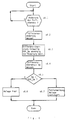
- FIGS. 3 to 5 serve to describe the previously indicated and further methods in more detail.
- the pressure difference Dp is measured after the start of the method (step s3.1), and then after passing through two marks A and B in a step s3.2 it is examined whether the measured pressure difference Dp is above a threshold value Dp_SW for a period of time ⁇ p that is longer than a threshold period of time ⁇ p_SW. If this is not the case, a final step se examines whether the method should be ended. If this is not the case, the processes run again from step s3.1. If it turns out in step s3.2 during one of the runs that the conditions queried there are both fulfilled, an error message is output in step s3.3 that the adsorption filter has insufficient throughput capability. On this signal z. B.
- a signal lamp is lit, which indicates that there is no serious error, but that a workshop should be visited in the near future.
- the error message can be stored in an error memory so that the workshop can quickly determine in the context of an error diagnosis why the signal lamp has been lit. After the error message has been issued, the end of the procedure is reached.
- Fig. 4 illustrates the case represented by the device by Fig. 1, namely that the pressure difference threshold value Dp_SW in step s3.2 in the method of Fig. 3 is not fixed, but depends on values of operating variables of the engine and the tank ventilation valve.
- steps s4.1 and s4.2 of FIG. 4 are inserted between marks A and B in the method of FIG. 3.
- step s4.1 values of operating variables of the engine and the tank ventilation valve, in the example of the speed n, the Load L and the duty cycle R are detected, and with the aid of these values a map is addressed in step s4.2, from which the current threshold value Dp_SW entered at the addressed location is read out.
- FIG. 5 illustrates a method according to the one that was explained above with reference to the device from FIG. 2.
- step s5.1 it is examined whether the tank ventilation valve has been closed. As soon as this is the case, a time measurement is started from the closing time T_0 and the differential pressure Dp_0 is detected when the valve closes (step s5.2). Further measurements of the differential pressure Dp take place at fixed times T after the closing time T_0 (step s5.3). With the help of the pressure difference values obtained as a function of time, the time constant ⁇ for reducing the pressure difference Dp is determined (step s5.4).
- a query is made as to whether the time period ⁇ determined in this way lies above a threshold ⁇ _SW. If this is the case, in step s5.6 there is a measure for error output which corresponds to that as explained above with reference to step s3.3, whereupon the method is ended. If, on the other hand, it is found in step s5.5 that the time constant ⁇ does not exceed the threshold mentioned, an end step se in turn asks whether the method should be ended. If this is not the case, the process is carried out again from step s5.1.
- the differential pressure Dp is measured at the tank 15 or at the adsorption filter 14.
- the manner in which the connecting line 16 is introduced into the adsorption filter 14 is also not apparent.
- the optimal solution can be determined by test bench tests.
- the method according to FIG. 6 is used to check whether an OBVR tank ventilation system is blocked, in particular the adsorption filter of such a system.
- OBVR on-board vapor recovery
- step s6.1 it is examined whether the fill level in the tank changes. This step is used to determine whether the vehicle is being fueled. If another sensor is available, its signal can also be used. If refueling is determined, the change in level is measured (step s6.2) and a differential overpressure threshold DSP_SW is determined with the aid of the measurement result (step s6.3). If a fixed threshold is used, steps s6.2 and s6.3 are omitted. The differential overpressure Dp is then measured (step s6.4) and the measured value is compared with the aforementioned threshold DSP_SW (step s6.5). If it is found that the measured value does not exceed the threshold value, the system is assessed as being free (step s6.6). Otherwise an error message is output (step s6.7), which indicates that the system is clogged. This message can be entered in an error memory. In addition, a warning lamp is advantageously lit to indicate to a driver that a workshop should be visited.
- the differential overpressure Dp measured in step s6.4 is the pressure difference between the internal pressure of the tank ventilation system and the ambient pressure. If the differential pressure meter for detecting this differential pressure is arranged on the tank, as shown in FIG. 1, all blockages between the tank and the ventilation line of the adsorption filter can be determined immediately by an excessive pressure increase. In the case of a type of attachment according to FIG. 2 on the adsorption filter, on the other hand, blockages of the adsorption filter due to excessively high pressure and blockages between the tank and adsorption filter become noticeable due to particularly low excess pressure when refueling.
Landscapes
- Engineering & Computer Science (AREA)
- Chemical & Material Sciences (AREA)
- Combustion & Propulsion (AREA)
- Mechanical Engineering (AREA)
- General Engineering & Computer Science (AREA)
- Supplying Secondary Fuel Or The Like To Fuel, Air Or Fuel-Air Mixtures (AREA)
- Cooling, Air Intake And Gas Exhaust, And Fuel Tank Arrangements In Propulsion Units (AREA)
Abstract
Claims (12)
- Procédé pour contrôler le bon fonctionnement d'une installation de ventilation du réservoir d'un véhicule équipé d'un moteur à combustion interne (10), installation qui présente un filtre d'aspiration (14) avec une ouverture de ventilation (17) sur le côté de sa ventilation et avec une conduite de raccordement (16) allant à un réservoir (15) et une soupape de ventilation du réservoir (13), qui est branchée dans une conduite de liaison (12), située entre le tuyau d'aspiration (11) du moteur et le côté de l'aspiration du filtre d'aspiration,
caractérisé en ce que- quand la soupape de ventilation du réservoir (13) est commandée pour s'ouvrir, et- si c'est le cas, quand la soupape commandée pour s'ouvrir (17.1) est dans l'ouverture de ventilation (17),- on mesure une pression différentielle (Dp), entre le côté de la ventilation ou l'environnement et le côté de l'aspiration du filtre d'aspiration. - Procédé selon la revendication 1,
caractérisé en ce que
la pression différentielle mesurée (Dp) doit dépasser la valeur de seuil (Dp_SW) pendant au moins un intervalle de temps prédéfini (Δt_SW), afin de pouvoir conclure à une insuffisance du filtre d'aspiration (14) en ce qui concerne son débit. - Procédé selon l'une des revendications 1 ou 2,
caractérisé en ce que- l'on détecte des valeurs de grandeurs de fonctionnement (n, L, R) du moteur (10) et de la soupape de ventilation du réservoir (13), et- l'on prédéfinit la valeur de seuil (Dp_SW) en fonction des valeurs détectées des grandeurs des états de fonctionnement. - Procédé pour contrôler le bon fonctionnement d'une installation de ventilation du réservoir d'un véhicule équipé d'un moteur à combustion interne (10), installation qui présente un filtre d'aspiration (14) avec une ouverture de ventilation (17) sur le côté de sa ventilation et avec une conduite de raccordement (16) allant à un réservoir (15) et une soupape de ventilation du réservoir (13), qui est branchée dans une conduite de liaison (12), située entre le tuyau d'aspiration (11) du moteur et le côté de l'aspiration du filtre d'aspiration,
caractérisé en ce qu'- après le déroulement d'une phase de régénération d'une durée prédéfinie dans le cas où la soupape de ventilation du réservoir (13) est ouverte, et- si c'est le cas, quand la soupape commandée (17.1) est dans l'ouverture d'aération (17), dans la phase dans laquelle il s'est établi une dépression dans l'installation de ventilation du réservoir, la soupape de ventilation du réservoir se ferme et lors sensiblement de la fermeture de celle-ci, une pression différentielle (Dp) est mesurée entre le côté de la ventilation ou l'environnement et le côté de l'aspiration du filtre d'aspiration,- la constante de temps (tau) pour la chute de la différence de pression mesurée, après la fermeture de la soupape de ventilation du réservoir, est déterminée à l'aide d'au moins une autre mesure de pression différentielle, et- l'on conclue à une insuffisance du débit du filtre d'aspiration, quand la constante de temps déterminée est plus longue qu'une constante de temps de valeur de seuil (tauSW). - Procédé selon la revendication 4,
caractérisé en ce que
la constante de temps de valeur de seuil (τ_SW) est prédéfinie en fonction de l'état de remplissage du réservoir. - Procédé selon l'une des revendications 1 à 5,
caractérisé en ce que
l'on mesure comme pression différentielle (Dp) la différence entre la pression sur le côté de l'aspiration du filtre d'aspiration (14) et la pression ambiante. - Procédé selon l'une des revendications 1 à 5,
caractérisé en ce que
l'on mesure comme pression différentielle (Dp) la différence entre la pression dans le réservoir (15) et la pression ambiante. - Procédé pour contrôler le bon fonctionnement d'une installation de ventilation du réservoir d'un véhicule équipé d'un moteur à combustion interne (10), installation qui présente un filtre d'aspiration (14) avec une ouverture de ventilation (17) sur le côté de sa ventilation et avec une conduite de raccordement (16) allant à un réservoir (15) et une soupape de ventilation du réservoir (13), qui est branchée dans une conduite de liaison (12), située entre le tuyau d'aspiration (11) du moteur et le côté de l'aspiration du filtre d'aspiration, installation qui est constituée d'une manière telle que lors du remplissage du réservoir avec le pistolet de distribution de carburant on assure l'étanchéité par rapport à l'ajutage du réservoir,
caractérisé en ce qu'- on détecte si un remplissage s'effectue,- au cas où l'on détecte qu'un remplissage s'effectue, la soupape de ventilation du réservoir (13) étant fermée pendant le remplissage du réservoir, on mesure la surpression différentielle (Dp), qui correspond à la différence entre la pression intérieure de l'installation de ventilation du réservoir et la pression ambiante, et- on considère que l'installation de ventilation du réservoir est bouchée, quand la surpression différentielle mesurée dépasse une valeur de seuil de surpression différentielle (Dp>DSpSW). - Procédé selon la revendication 8,
caractérisé en ce que
la valeur de seuil de surpression différentielle (DSP_SW) est prédéfinie en fonction de la variation d'un signal de remplissage. - Dispositif, pour contrôler le bon fonctionnement d'une installation de ventilation du réservoir d'un véhicule équipé d'un moteur à combustion interne (10), installation qui présente un filtre d'aspiration (14) avec une ouverture de ventilation (17) sur le côté de sa ventilation et avec une conduite de raccordement (16) allant à un réservoir (15) et une soupape de ventilation du réservoir (13), qui est branchée dans une conduite de liaison (12), située entre le tuyau d'aspiration (11) du moteur et le côté de l'aspiration du filtre d'aspiration,
caractérisé par- un capteur de pression différentielle, qui mesure la pression différentielle entre le côté de la ventilation ou l'environnement et le côté de l'aspiration du filtre à charbon actif, qui quand le moteur à combustion interne est en fonctionnement alors que la soupape de ventilation du réservoir (13) est ouverte, et- si c'est le cas, quand la soupape (17.1) est ouverte dans l'ouverture de ventilation (17), et- grâce à un dispositif d'estimation, qui reçoit le signal du capteur de pression différentielle, et délivre un signal de défaut, indique l'insuffisance du filtre d'aspiration quant à son débit, quand la pression différentielle mesurée dépasse une valeur de seuil. - Dispositif, pour contrôler le bon fonctionnement d'une installation de ventilation du réservoir d'un véhicule équipé d'un moteur à combustion interne (10), installation qui présente un filtre d'aspiration (14) avec une ouverture de ventilation (17) sur le côté de sa ventilation et avec une conduite de raccordement (16) allant à un réservoir (15) et une soupape de ventilation du réservoir (13), qui est branchée dans une conduite de liaison (12), située entre le tuyau d'aspiration (11) du moteur et le côté de l'aspiration du filtre d'aspiration,
caractérisé par- un capteur de pression différentielle (18.2), qui mesure la pression différentielle (DP) entre le côté de la ventilation ou l'environnement et le côté de l'aspiration du filtre d'aspiration,- un dispositif de détermination (25), qui reçoit le signal du capteur de pression différentielle et en outre un signal, qui indique la fermeture de la soupape de ventilation du réservoir, et qui détermine la constante de temps (tau) de la chute de la pression différentielle mesurée après la fermeture de la soupape de ventilation du réservoir à l'aide des signaux de la pression différentielle qui lui sont amenés, et- un dispositif d'estimation (23, 2), qui reçoit le signal du dispositif de détermination et qui délivre un signal de défaut, qui indique une insuffisance du filtre d'aspiration quant à son débit, quand la constante de temps (tau) déterminée dépasse une valeur de seuil (tauSW). - Dispositif, pour contrôler le bon fonctionnement d'une installation de ventilation du réservoir d'un véhicule équipé d'un moteur à combustion interne (10), installation qui présente un filtre d'aspiration (14) avec une ouverture de ventilation (17) sur le côté de sa ventilation et avec une conduite de raccordement (16) allant à un réservoir (15) et une soupape de ventilation du réservoir (13), qui est branchée dans une conduite de liaison (12), située entre le tuyau d'aspiration (11) du moteur et le côté de l'aspiration du filtre d'aspiration,
caractérisé par- un capteur de pression différentielle (18.2), qui mesure la pression différentielle (DP) entre la pression intérieure de l'installation de ventilation du réservoir et la pression ambiante,- un dispositif de détermination, qui détecte si l'on remplit le réservoir, et- un dispositif d'estimation, qui considère que l'installation de ventilation du réservoir est bouchée , quand, dans le cas ou l'on remplit le réservoir, la pression différentielle dépasse une valeur de seuil de surpression différentielle (DP>DSPSW).
Applications Claiming Priority (3)
| Application Number | Priority Date | Filing Date | Title |
|---|---|---|---|
| DE4111360 | 1991-04-09 | ||
| DE4111360A DE4111360A1 (de) | 1991-04-09 | 1991-04-09 | Verfahren und vorrichtung zum pruefen einer tankentluefungsanlage |
| PCT/DE1992/000129 WO1992018764A1 (fr) | 1991-04-09 | 1992-02-21 | Procede et dispositif pour essayer un systeme d'aeration de reservoir de carburant |
Publications (2)
| Publication Number | Publication Date |
|---|---|
| EP0580603A1 EP0580603A1 (fr) | 1994-02-02 |
| EP0580603B1 true EP0580603B1 (fr) | 1997-05-21 |
Family
ID=6429081
Family Applications (1)
| Application Number | Title | Priority Date | Filing Date |
|---|---|---|---|
| EP92906112A Expired - Lifetime EP0580603B1 (fr) | 1991-04-09 | 1992-02-21 | Procede et dispositif pour essayer un systeme d'aeration de reservoir de carburant |
Country Status (5)
| Country | Link |
|---|---|
| US (1) | US5505182A (fr) |
| EP (1) | EP0580603B1 (fr) |
| JP (1) | JP3322872B2 (fr) |
| DE (2) | DE4111360A1 (fr) |
| WO (1) | WO1992018764A1 (fr) |
Families Citing this family (16)
| Publication number | Priority date | Publication date | Assignee | Title |
|---|---|---|---|---|
| DE4216067C2 (de) * | 1992-05-15 | 2002-12-05 | Bosch Gmbh Robert | Verfahren und Vorrichtung zur Tankentlüftungs-Diagnose bei einem Kraftfahrzeug |
| DE4232148A1 (de) * | 1992-09-25 | 1994-03-31 | Bayerische Motoren Werke Ag | Verfahren zur Dichtheitsprüfung einer Tankanlage für Kraftfahrzeuge |
| DE4303997B4 (de) * | 1993-02-11 | 2006-04-20 | Robert Bosch Gmbh | Verfahren und Vorrichtung zur Tankentlüftungsdiagnose bei einem Kraftfahrzeug |
| US5333590A (en) * | 1993-04-26 | 1994-08-02 | Pilot Industries, Inc. | Diagnostic system for canister purge system |
| JPH08226355A (ja) * | 1995-02-21 | 1996-09-03 | Toyota Motor Corp | 内燃機関の蒸発燃料処理装置 |
| JP3139318B2 (ja) * | 1995-02-27 | 2001-02-26 | トヨタ自動車株式会社 | エバポパージシステムの故障診断装置 |
| JP3272184B2 (ja) * | 1995-03-03 | 2002-04-08 | 本田技研工業株式会社 | 内燃エンジンの蒸発燃料処理装置 |
| DE19538775A1 (de) * | 1995-10-18 | 1997-04-24 | Bosch Gmbh Robert | Verfahren zur pneumatischen Prüfung der Funktionsfähigkeit einer Tankentlüftungsanlage |
| US5915282A (en) * | 1995-12-14 | 1999-06-22 | Abbott Laboratories | Fluid handler and method of handling a fluid |
| US5957115A (en) * | 1997-02-12 | 1999-09-28 | Siemens Canada Limited | Pulse interval leak detection system |
| DE19836295B4 (de) * | 1998-08-11 | 2004-07-08 | Robert Bosch Gmbh | Verfahren zur Prüfung der Funktionsfähigkeit einer Tankentlüftungsanlage eines Fahrzeugs |
| DE19910486A1 (de) * | 1999-03-10 | 2000-09-14 | Bielomatik Leuze & Co | Einrichtung und Verfahren zur Durchflußprüfung eines Behälter-Anschlusses |
| US6564782B2 (en) | 2001-02-21 | 2003-05-20 | Denso Corporation | Device for detecting canister deterioration |
| DE102007061073A1 (de) * | 2007-12-18 | 2009-06-25 | Dr. Ing. H.C. F. Porsche Aktiengesellschaft | Prüfverfahren zur Bestimmung des Alterungsverhaltens eines Aktivkohlefilters |
| EP3256728B1 (fr) * | 2015-02-13 | 2021-04-07 | Fluid Handling LLC. | Moyen de détection de non-écoulement pour des applications de commande de pompage sans capteur |
| JP6642329B2 (ja) | 2016-08-10 | 2020-02-05 | 株式会社デンソー | 蒸発燃料処理システム |
Family Cites Families (13)
| Publication number | Priority date | Publication date | Assignee | Title |
|---|---|---|---|---|
| JPH073211B2 (ja) * | 1985-07-17 | 1995-01-18 | 日本電装株式会社 | 燃料蒸発ガス排出抑止装置 |
| US4887578A (en) * | 1987-09-25 | 1989-12-19 | Colt Industries, Inc. | On board refueling vapor recovery system |
| US4926825A (en) * | 1987-12-07 | 1990-05-22 | Honda Giken Kogyo K.K. (Honda Motor Co., Ltd. In English) | Air-fuel ratio feedback control method for internal combustion engines |
| JPH0623736Y2 (ja) * | 1988-08-10 | 1994-06-22 | トヨタ自動車株式会社 | 内燃機関のエバポパージ異常検出装置 |
| FR2635823B1 (fr) * | 1988-08-29 | 1990-11-30 | Bendix Electronics Sa | Dispositif de verification de l'etat de fonctionnement d'un systeme de recuperation de vapeurs issues d'un reservoir d'essence de vehicule automobile |
| JPH0235952U (fr) * | 1988-08-29 | 1990-03-08 | ||
| JP2586425B2 (ja) * | 1988-10-07 | 1997-02-26 | 日本電装株式会社 | 燃料蒸発ガス処理手段の診断装置 |
| JP2689538B2 (ja) * | 1988-11-11 | 1997-12-10 | 株式会社デンソー | 燃料蒸発ガス拡散防止装置における自己診断装置 |
| DE3909887A1 (de) * | 1989-03-25 | 1990-09-27 | Bosch Gmbh Robert | Verfahren und vorrichtung zur ueberpruefung der steuerbarkeit eines tankentlueftungsventils |
| EP0411173B1 (fr) * | 1989-07-31 | 1992-12-23 | Siemens Aktiengesellschaft | Disposition et procédé de détection d'erreurs dans un système de ventilation de réservoir à carburant |
| DE4003751C2 (de) * | 1990-02-08 | 1999-12-02 | Bosch Gmbh Robert | Tankentlüftungsanlage für ein Kraftfahrzeug und Verfahren zum Überprüfen deren Funktionstüchtigkeit |
| DE4012111C1 (fr) * | 1990-04-14 | 1991-03-07 | Audi Ag, 8070 Ingolstadt, De | |
| US5085194A (en) * | 1990-05-31 | 1992-02-04 | Honda Giken Kogyo K.K. | Method of detecting abnormality in an evaporative fuel-purging system for internal combustion engines |
-
1991
- 1991-04-09 DE DE4111360A patent/DE4111360A1/de not_active Withdrawn
-
1992
- 1992-02-21 WO PCT/DE1992/000129 patent/WO1992018764A1/fr not_active Ceased
- 1992-02-21 US US08/133,054 patent/US5505182A/en not_active Expired - Lifetime
- 1992-02-21 DE DE59208524T patent/DE59208524D1/de not_active Expired - Lifetime
- 1992-02-21 EP EP92906112A patent/EP0580603B1/fr not_active Expired - Lifetime
- 1992-02-21 JP JP50591992A patent/JP3322872B2/ja not_active Expired - Lifetime
Also Published As
| Publication number | Publication date |
|---|---|
| US5505182A (en) | 1996-04-09 |
| EP0580603A1 (fr) | 1994-02-02 |
| DE59208524D1 (de) | 1997-06-26 |
| DE4111360A1 (de) | 1992-10-15 |
| JPH06506514A (ja) | 1994-07-21 |
| JP3322872B2 (ja) | 2002-09-09 |
| WO1992018764A1 (fr) | 1992-10-29 |
Similar Documents
| Publication | Publication Date | Title |
|---|---|---|
| EP0578795B1 (fr) | Procede et dispositif pour verifier l'aptitude a fonctionner d'une installation de degazage de reservoir | |
| EP0580603B1 (fr) | Procede et dispositif pour essayer un systeme d'aeration de reservoir de carburant | |
| EP0559854B1 (fr) | Procede et dispositif pour controler la capacite fonctionnelle d'un systeme de degazage du reservoir | |
| DE19636431B4 (de) | Verfahren und Vorrichtung zur Prüfung der Funktionsfähigkeit einer Tankentlüftungsanlage | |
| DE69411153T2 (de) | Integritätsbestätigung eines knistersystems mit positivem druck | |
| DE69629404T2 (de) | Eine Fehlerdiagnosevorrichtung für Kraftstoffdampfentlüftungsanlage | |
| DE19702584C2 (de) | Verdampfersystem und Verfahren für dessen Diagnose | |
| DE4108856C2 (de) | Tankentlüftungsanlage sowie Verfahren und Vorrichtung zum Überprüfen der Dichtheit derselben | |
| DE69409098T2 (de) | Integritätsbestätigung eines kanistersystems mit positivem druck | |
| DE19755401C2 (de) | Diagnosevorrichtung für Verdampfungssystem | |
| DE19713085C2 (de) | Verfahren zum Überprüfen der Funktionstüchtigkeit einer Tankentlüftungsanlage für ein Kraftfahrzeug | |
| DE102012202236A1 (de) | System und verfahren zum ausführen einer kraftstoffdampfleckdiagnose in einem fahrzeug | |
| DE10028157A1 (de) | Kraftstoffanlagen-Leckerkennung | |
| DE19518292C2 (de) | Verfahren zur Diagnose eines Tankentlüftungssystems | |
| DE102013218306A1 (de) | Erfassung von Kurbelgehäuse-Unversehrtheitsverletzungen | |
| EP0535183B1 (fr) | Procede et dispositif pour surveiller le fonctionnement d'un systeme d'aeration de reservoir de carburant | |
| DE19946874A1 (de) | Diagnose von Stellgliedern und Sensoren in Verbindung mit der Gemischbildung bei Brennkraftmaschinen | |
| DE19755401A9 (de) | Diagnosevorrichtung für Verdampfungssystem | |
| EP0952332B1 (fr) | Procédé pour détecter des fuites dans les systèmes d'admission de carburant pour un véhicule | |
| DE4216067C2 (de) | Verfahren und Vorrichtung zur Tankentlüftungs-Diagnose bei einem Kraftfahrzeug | |
| DE4126880A1 (de) | Tankentlueftungsanlage sowie verfahren und vorrichtung zum ueberpruefen von deren funktionsfaehigkeit | |
| DE112012005026T5 (de) | Verfahren zum Ermitteln einer Leckage in einem Dampfmanagementsystem eines Kraftstoffsystems eines Kraftfahrzeugs sowie Dampfmanagementsysteme für ein Kraftfahrzeug mit Mitteln zum Ermitteln von Leckagen | |
| EP0503280A2 (fr) | Dispositif pour mesurer la teneur en carburant dans un réservoir | |
| DE10252225A1 (de) | Verfahren zur Bestimmung des Kraftstoff-Dampfdrucks in einem Kraftfahrzeug mit Bordmitteln | |
| DE10223513B4 (de) | Fehlfunktionsdiagnosesystem eines Verdampfungskraftstoff-Verarbeitungssystems |
Legal Events
| Date | Code | Title | Description |
|---|---|---|---|
| PUAI | Public reference made under article 153(3) epc to a published international application that has entered the european phase |
Free format text: ORIGINAL CODE: 0009012 |
|
| 17P | Request for examination filed |
Effective date: 19930904 |
|
| AK | Designated contracting states |
Kind code of ref document: A1 Designated state(s): DE FR GB IT SE |
|
| 17Q | First examination report despatched |
Effective date: 19950215 |
|
| GRAG | Despatch of communication of intention to grant |
Free format text: ORIGINAL CODE: EPIDOS AGRA |
|
| GRAH | Despatch of communication of intention to grant a patent |
Free format text: ORIGINAL CODE: EPIDOS IGRA |
|
| GRAH | Despatch of communication of intention to grant a patent |
Free format text: ORIGINAL CODE: EPIDOS IGRA |
|
| GRAA | (expected) grant |
Free format text: ORIGINAL CODE: 0009210 |
|
| AK | Designated contracting states |
Kind code of ref document: B1 Designated state(s): DE FR GB IT SE |
|
| REF | Corresponds to: |
Ref document number: 59208524 Country of ref document: DE Date of ref document: 19970626 |
|
| ET | Fr: translation filed | ||
| GBT | Gb: translation of ep patent filed (gb section 77(6)(a)/1977) |
Effective date: 19970729 |
|
| PLBE | No opposition filed within time limit |
Free format text: ORIGINAL CODE: 0009261 |
|
| STAA | Information on the status of an ep patent application or granted ep patent |
Free format text: STATUS: NO OPPOSITION FILED WITHIN TIME LIMIT |
|
| 26N | No opposition filed | ||
| REG | Reference to a national code |
Ref country code: GB Ref legal event code: IF02 |
|
| PGFP | Annual fee paid to national office [announced via postgrant information from national office to epo] |
Ref country code: GB Payment date: 20020211 Year of fee payment: 11 |
|
| PGFP | Annual fee paid to national office [announced via postgrant information from national office to epo] |
Ref country code: FR Payment date: 20020221 Year of fee payment: 11 |
|
| PG25 | Lapsed in a contracting state [announced via postgrant information from national office to epo] |
Ref country code: GB Free format text: LAPSE BECAUSE OF NON-PAYMENT OF DUE FEES Effective date: 20030221 |
|
| GBPC | Gb: european patent ceased through non-payment of renewal fee | ||
| PG25 | Lapsed in a contracting state [announced via postgrant information from national office to epo] |
Ref country code: FR Free format text: LAPSE BECAUSE OF NON-PAYMENT OF DUE FEES Effective date: 20031031 |
|
| REG | Reference to a national code |
Ref country code: FR Ref legal event code: ST |
|
| PGFP | Annual fee paid to national office [announced via postgrant information from national office to epo] |
Ref country code: SE Payment date: 20040227 Year of fee payment: 13 |
|
| PG25 | Lapsed in a contracting state [announced via postgrant information from national office to epo] |
Ref country code: IT Free format text: LAPSE BECAUSE OF NON-PAYMENT OF DUE FEES Effective date: 20050221 |
|
| PG25 | Lapsed in a contracting state [announced via postgrant information from national office to epo] |
Ref country code: SE Free format text: LAPSE BECAUSE OF NON-PAYMENT OF DUE FEES Effective date: 20050222 |
|
| EUG | Se: european patent has lapsed | ||
| PGFP | Annual fee paid to national office [announced via postgrant information from national office to epo] |
Ref country code: DE Payment date: 20110421 Year of fee payment: 20 |
|
| REG | Reference to a national code |
Ref country code: DE Ref legal event code: R071 Ref document number: 59208524 Country of ref document: DE |
|
| REG | Reference to a national code |
Ref country code: DE Ref legal event code: R071 Ref document number: 59208524 Country of ref document: DE |
|
| PG25 | Lapsed in a contracting state [announced via postgrant information from national office to epo] |
Ref country code: DE Free format text: LAPSE BECAUSE OF EXPIRATION OF PROTECTION Effective date: 20120222 |