EP0581966B1 - Moteur equipe d'un moyen de refroidissement du stator - Google Patents
Moteur equipe d'un moyen de refroidissement du stator Download PDFInfo
- Publication number
- EP0581966B1 EP0581966B1 EP93904326A EP93904326A EP0581966B1 EP 0581966 B1 EP0581966 B1 EP 0581966B1 EP 93904326 A EP93904326 A EP 93904326A EP 93904326 A EP93904326 A EP 93904326A EP 0581966 B1 EP0581966 B1 EP 0581966B1
- Authority
- EP
- European Patent Office
- Prior art keywords
- stator core
- heat
- windings
- laminated stator
- cooling
- Prior art date
- Legal status (The legal status is an assumption and is not a legal conclusion. Google has not performed a legal analysis and makes no representation as to the accuracy of the status listed.)
- Expired - Lifetime
Links
- 238000001816 cooling Methods 0.000 title claims description 21
- 238000004804 winding Methods 0.000 claims abstract description 54
- 239000008187 granular material Substances 0.000 claims abstract description 11
- TWNQGVIAIRXVLR-UHFFFAOYSA-N oxo(oxoalumanyloxy)alumane Chemical compound O=[Al]O[Al]=O TWNQGVIAIRXVLR-UHFFFAOYSA-N 0.000 claims abstract description 5
- 239000012260 resinous material Substances 0.000 claims description 22
- 239000002131 composite material Substances 0.000 claims description 21
- 239000002826 coolant Substances 0.000 claims description 16
- 229920006015 heat resistant resin Polymers 0.000 claims description 3
- 239000000110 cooling liquid Substances 0.000 abstract description 25
- 229920005989 resin Polymers 0.000 abstract description 7
- 239000011347 resin Substances 0.000 abstract description 7
- 239000000463 material Substances 0.000 abstract description 4
- 239000000805 composite resin Substances 0.000 abstract 2
- 238000000034 method Methods 0.000 description 9
- 239000000945 filler Substances 0.000 description 7
- XEEYBQQBJWHFJM-UHFFFAOYSA-N Iron Chemical compound [Fe] XEEYBQQBJWHFJM-UHFFFAOYSA-N 0.000 description 6
- RYGMFSIKBFXOCR-UHFFFAOYSA-N Copper Chemical compound [Cu] RYGMFSIKBFXOCR-UHFFFAOYSA-N 0.000 description 4
- 229910052802 copper Inorganic materials 0.000 description 4
- 239000010949 copper Substances 0.000 description 4
- 230000000694 effects Effects 0.000 description 4
- 239000003822 epoxy resin Substances 0.000 description 3
- 229910052742 iron Inorganic materials 0.000 description 3
- 238000000465 moulding Methods 0.000 description 3
- 229920000647 polyepoxide Polymers 0.000 description 3
- 229920001187 thermosetting polymer Polymers 0.000 description 3
- 238000010438 heat treatment Methods 0.000 description 2
- 229920003002 synthetic resin Polymers 0.000 description 2
- 239000000057 synthetic resin Substances 0.000 description 2
- 229910000976 Electrical steel Inorganic materials 0.000 description 1
- 239000000853 adhesive Substances 0.000 description 1
- 230000001070 adhesive effect Effects 0.000 description 1
- 238000010276 construction Methods 0.000 description 1
- 239000000112 cooling gas Substances 0.000 description 1
- 230000005484 gravity Effects 0.000 description 1
- 230000020169 heat generation Effects 0.000 description 1
- 238000003475 lamination Methods 0.000 description 1
- 230000002093 peripheral effect Effects 0.000 description 1
- 238000007789 sealing Methods 0.000 description 1
- 239000000126 substance Substances 0.000 description 1
Images


Classifications
-
- H—ELECTRICITY
- H02—GENERATION; CONVERSION OR DISTRIBUTION OF ELECTRIC POWER
- H02K—DYNAMO-ELECTRIC MACHINES
- H02K1/00—Details of the magnetic circuit
- H02K1/06—Details of the magnetic circuit characterised by the shape, form or construction
- H02K1/12—Stationary parts of the magnetic circuit
- H02K1/20—Stationary parts of the magnetic circuit with channels or ducts for flow of cooling medium
-
- H—ELECTRICITY
- H02—GENERATION; CONVERSION OR DISTRIBUTION OF ELECTRIC POWER
- H02K—DYNAMO-ELECTRIC MACHINES
- H02K9/00—Arrangements for cooling or ventilating
- H02K9/22—Arrangements for cooling or ventilating by solid heat conducting material embedded in, or arranged in contact with, the stator or rotor, e.g. heat bridges
- H02K9/223—Heat bridges
-
- H—ELECTRICITY
- H02—GENERATION; CONVERSION OR DISTRIBUTION OF ELECTRIC POWER
- H02K—DYNAMO-ELECTRIC MACHINES
- H02K9/00—Arrangements for cooling or ventilating
- H02K9/19—Arrangements for cooling or ventilating for machines with closed casing and closed-circuit cooling using a liquid cooling medium, e.g. oil
- H02K9/197—Arrangements for cooling or ventilating for machines with closed casing and closed-circuit cooling using a liquid cooling medium, e.g. oil in which the rotor or stator space is fluid-tight, e.g. to provide for different cooling media for rotor and stator
-
- H—ELECTRICITY
- H02—GENERATION; CONVERSION OR DISTRIBUTION OF ELECTRIC POWER
- H02K—DYNAMO-ELECTRIC MACHINES
- H02K9/00—Arrangements for cooling or ventilating
- H02K9/22—Arrangements for cooling or ventilating by solid heat conducting material embedded in, or arranged in contact with, the stator or rotor, e.g. heat bridges
- H02K9/227—Heat sinks
Definitions
- the present invention relates to an electric motor having means for cooling a stator, and more particularly to an electric motor having means for cooling windings arranged within slots of the stator by absorbing the heat generated by the windings, and thus removing heat generated in the stator.
- various cooling structures for an electric motor are used, such as a structure in which heat generated in a stator is absorbed through a stator core, or a structure in which heat generated in a rotor is absorbed through a rotating shaft.
- US-A-4,213,745 discloses a pump for a central heating system having a tubular housing and an electric motor in which the peripheral cavities defined between windings and two cup-shaped members are filled with a curable filler such as a epoxy resin to reduce the effect of small movement of the laminations or the windings. Although, this filler thermally connects the windings to the cup-shaped members, it did not have such a heat conductivity to obtain a substantial cooling effect for the windings.
- a curable filler such as a epoxy resin
- EP-A-0 321 582 further discloses a method of applying a synthetic resin which is coated on a stator core and windings.
- this synthetic resin also does not have a heat conductivity to obtain an effective cooling of the windings.
- a heat-absorbing, cooling structure for a stator in that an outer casing is fixed in close contact with an outer surface of a stator core surrounding a rotor, passages for a cooling medium are formed in the outer casing, and the heat generated by the stator core is absorbed by the cooling medium.
- a structure is also known, in that cooling medium passages are directly formed within a stator core, so as to improve the cooling effect (see, e.g., Japanese Unexamined Patent Publication (Kokai) No. 2-263743).
- the above-mentioned cooling structures it is possible to cool the stator of an electric motor by absorbing the heat generated mainly by the stator core.
- the heat generation in a stator is not only caused by iron loss but also by the copper loss in the windings arranged in the stator core.
- the above-mentioned conventional cooling structure cannot directly absorb the heat generated from the windings.
- the heat of the windings is partially transmitted and absorbed through the stator core, but is mostly emitted from the coil-ends of the windings, which project from the axial end faces of the stator core, into the atmosphere.
- it is difficult to obtain a substantial cooling effect for the windings.
- the object of the present invention is to provide an electric motor having cooling means that can effectively cool a stator by absorbing the heat generated by a stator core due to iron loss and the heat generated by the windings arranged in the stator core due to copper loss, and thus can improve the performance of the electric motor.
- the present invention provides an electric motor having means for cooling a stator, comprising front and rear housing members;
- the heat-transfer member may be molded by a process in that the composite heat-conductive resinous material is poured into spaces defined between the windings and the inner surfaces of the slots of the laminated stator core and the housing in a molten state, and then the composite heat-conductive resinous material is set.
- the heat-transfer member may be formed from composite heat-conductive resinous material which is molded by a process in that the granular materials are filled into spaces defined between the windings and the inner surfaces of the slots of the laminated stator core and of the housing, the heat-resistant resin is poured, in a molten state, onto the granular materials, and then the resin is set.
- the granular materials mixed into the composite heat-conductive resinous material of the heat-transfer member comprise aluminum oxide granules.
- the housing comprises a pair of housing members that support the laminated stator core axially therebetween, and that the cooling medium circuit is formed in the laminated stator core and the housing members, and continuously extends along the axial entire length of the laminated stator core and a projecting length of the coil-ends of the windings.
- Heat generated, due to copper loss, by the windings arranged on the laminated stator core is transmitted to the heat-transfer member covering the windings.
- the heat-transfer member made of composite heat-conductive resinous material effectively transfers the heat to the laminated stator core and the housing.
- the heat transferred to the laminated stator core and the housing is absorbed by the cooling medium passing through the cooling medium circuit.
- heat generated due to iron loss from the laminated stator core is also absorbed by the cooling medium passing through the cooling medium circuit. Therefore, heat generated by the windings and the laminated stator core is efficiently absorbed by the cooling medium, and thus the stator is effectively cooled.
- Figure 1 shows a sectional view of an electric motor having means for cooling a stator, according to the embodiment of the present invention.
- the motor includes a rotor 10 arranged inside the motor and a stator 18 arranged at the outer periphery of the motor; the rotor 10 integrally having a rotating shaft 12; and the stator 18 having a laminated stator core 14 surrounding the rotor 10 with a predetermined space, and a plurality of windings 16 wound on the laminated stator core 14.
- a front housing 20 and a rear housing 22 are arranged at the axial front and rear ends of the motor, respectively, for carrying the rotating shaft 12 of the rotor 10, and for supporting the laminated stator core 14 between the front and rear housings.
- the front housing 20 is provided with a bearing 24 at a center opening 20a, for rotatably supporting the rotating shaft 12 integrated into the rotor 10.
- the rear housing 22 includes an annular member 22a and a cap member 22b closely fitted with the annular member 22a, and is also provided with a bearing 24 at a center opening 22c formed inside the cap member 22b, so as to rotatably support the rotating shaft 12 of the rotor 10.
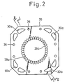
- the laminated stator core 14 is formed by stacking a plurality of thin-plate cores 26 of a silicon steel plate, as shown in Fig. 2, in an axial direction of the motor.
- the thin-plate core 26 is provided with an opening 26a at a center thereof for surrounding the rotor 10, and a plurality of slot holes 28a at a periphery of the opening 26a.
- the laminated stator core 14 is constructed so as to seal small gaps between the adjacent thin-plate cores 26, by stacking thin-plate cores 26 that are previously applied with a thermosetting adhesive onto both sides thereof, or by vacuum-impregnating a thermosetting resin into stacked thin-plate cores 26 and suitably heating the resin and cores.
- a plurality of slots 28 are formed by stacking the thin-plate cores 26 so as to communicate the slot holes 28a, and the windings 16 are disposed within the respective slots 28.
- each of the thin-plate cores 26 forming the laminated stator core 14 is provided with a plurality of cooling liquid passage holes 30a at four corners thereof, so as to define a cooling liquid circuit for cooling the stator 18.
- the cooling liquid passage holes 30a are communicated by stacking the thin-plate cores 26, and define cooling liquid passages 30 (Fig. 1) extending axially in the laminated stator core 14.
- the front housing 20 supporting the laminated stator core 14 is provided with connecting passages 32 for cooling liquid at positions corresponding to the cooling liquid passages 30, and the rear housing 22 is provided with connecting passages 34 for cooling liquid in the same manner.
- the laminated stator core 14, the front housing 20, and the rear housing 22 are fixed together by a plurality of tie-bolts (not shown).
- Fig. 2 shows bolt holes 36 for tie-bolts.
- the connecting passages 32, 34 of the front and rear housings 20, 22 connect the cooling liquid passages 30, being arranged at four corners of the laminated stator core 14, to one another in the respective housing 20, 22.
- the rear housing 22 is provided with an inlet and an outlet of cooling liquid (one 34a of which is shown in Fig. 1) connected to an external cooling liquid feed source.
- the cooling liquid is introduced into the cooling liquid passages 30 of the laminated stator core 14 through the inlet, and is discharged from the cooling liquid passages 30 through the outlet.
- a continuous cooling liquid circuit is defined from the cooling liquid inlet through the cooling liquid passages 30 and connecting passages 32, 34 to the cooling liquid outlet.
- known O-rings 38 are disposed at junctions between the cooling liquid passages 30 of the laminated stator core 14 and the connecting passages 32, 34 of the front and rear housings 20, 22, so as to ensure sealing of the junctions.
- the windings 16 wound on the laminated stator core 14 are covered over substantially the entire surfaces thereof, i.e., the surfaces of portions arranged in the slots 28 and of coil-ends 40 projecting from axial end faces of the laminated stator core 14, with heat-transfer members 42 that are made of the composite heat-conductive resinous material mentioned below.
- the composite heat-conductive resinous material is formed by mixing a highly heat-resistant, moldable resin, such as epoxy resin, with highly heat-conductive, electrically-insulative granular materials, such as aluminum oxide granules, as fillers.
- the composite heat-conductive resinous material is poured, in a molten state, into each space defined between the windings 16 and the inner surfaces of the slots 28 of the laminated stator core 14, and between the windings 16 and the inner surfaces of the front and rear housings 20, 22. Then, the composite heat-conductive resinous material is cold-set or thermoset, thereby the heat-transfer members 42 are formed so as to surround the windings 16 and to fill each space mentioned above.
- the heat-transfer members 42 thermally connect the windings 16 to the inner surfaces of the slots 28, and the windings 16 to the inner surfaces of the front and rear housings 20, 22.
- heat generated by the windings 16 is effectively transferred, through the heat-transfer members 42 made of composite heat-conductive resinous material, to the laminated stator core 14, the front housing 20, and the rear housing 22.
- the laminated stator core 14, the front housing 20, and the rear housing 22 are provided with the cooling liquid passages 30, the connecting passages 32, and the connecting passages 34, respectively, over the axial entire length of the windings 16, therefore the heat transferred to the laminated stator core 14 and the front and rear housings 20, 22 is effectively absorbed by the cooling liquid that passes through the cooling liquid passages 30 and the connecting passages 32, 34.
- the laminated stator core 14 is formed by stacking a plurality of thin-plate cores 26, and the stator 18 is constructed by arranging the windings 16 in the slots 28 of the laminated stator core 14.
- the stator 18 constructed in this manner is mounted between a pair of molds 44, 46, as shown in Fig. 3a, and is arranged on a work table (not shown) while vertically orienting the axis of the stator 18.
- the upper mold 46 is provided with a plurality of gates 48.
- Cores 50, 52, 54 are disposed at position in the center bore of the stator 18 for arranging the rotor 10 and at axial front and rear positions of the center bore, the resinous material being not pored into these positions.
- the composite heat-conductive resinous material 56 containing the filler is poured, in a molten state, into the gate 48 of the upper mold 46, and flows downward, by gravity, through gaps between the slots 28 of the laminated stator core 14 and the windings 16 to the lower mold 44.
- the other gate 48 acts as air vent.
- the composite heat-conductive resinous material 56 is poured successively into an annular cavity 56 defined between the lower mold 44 and the core 50, gaps 60 between the slots 28 as well as the core 52 and the windings 16, and an annular cavity 62 defined between the upper mold 46 and the core 54. Then, the composite heat-conductive resinous material 56 is suitably cold-set or thermo-set, and thus the heat-transfer member 42 is formed through the gaps 60 and the cavities 58, 62 (see Fig. 3b).
- the composite heat-conductive resinous material 56 cannot be sufficiently poured into the gaps and the cavities in the above method because of narrow spaces between the slots 28 of the laminated stator core 14 and the windings 16, e.g., particularly in the case of small sized motor, it is possible to separately pour the resin material and the filler of the composite heat-conductive resinous material 56. That is, only grained fillers of, e.g., aluminum oxide are put in each of the lower cavity 58, the gaps 60 between the slots 28 and the windings 16, and the upper cavity 62, and after that, an easily moldable resin such as epoxy resin is poured into each cavity or gap. According to this method, it becomes possible to pour the composite heat-conductive resinous material 56 into narrow spaces, and to improve the filler content.
- grained fillers of, e.g., aluminum oxide are put in each of the lower cavity 58, the gaps 60 between the slots 28 and the windings 16, and the upper cavity 62, and after that, an easily moldable resin such as epoxy resin is poured into
- the motor shown in Fig. 1 is constructed by inserting the rotor 10 into and fixing the front and rear housings 20, 22 to the stator 18, which is provided with the heat-transfer members 42 surrounding the windings 16 at the axial front and rear ends of the laminated stator core 14 and in the slots 28 thereof.
- the stator 18 which is provided with the heat-transfer members 42 surrounding the windings 16 at the axial front and rear ends of the laminated stator core 14 and in the slots 28 thereof.
- the above-mentioned second method is adopted.
- the windings 16 are covered with the heat-transfer members 42, the risk of substances entering the motor from the outside and adhering to the coil-ends 40, so as to cause a damage such as a short circuit, is eliminated.
- a cooling medium for cooling the laminated stator core 14 and the windings 16 is described as a cooling liquid, but of course the present invention may be applied for a gas-cooled electric motor using a cooling gas. Also, the present invention may be applied for a cooling structure in which a cooling medium circuit is formed in an outer housing fixed in close contact with the outer periphery of a laminated stator core.
- the present invention has a construction in which a cooling medium circuit is formed in the housing and/or the laminated stator core of an electric motor so as to extend over the entire length of the laminated stator core and the projecting length of the coil-ends of the windings arranged on the laminated stator core, and heat-transfer members, being molded from composite heat-conductive resinous material, are arranged in spaces between the windings and the inner surfaces of slots and the housing so as to cover the windings and to thermally connect the windings with the laminated stator core and the housing, thereby heat generated by the windings passes through the heat-transfer members, the laminated stator core, and the housing, and is absorbed by cooling medium passing through the circuit. Therefore, heat generated by the windings and the laminated stator core is efficiently absorbed by the cooling medium, and the stator is more effectively cooled, so that the heat loss of an electric motor is reduced and the performance thereof is improved.
Landscapes
- Engineering & Computer Science (AREA)
- Power Engineering (AREA)
- Motor Or Generator Cooling System (AREA)
- Iron Core Of Rotating Electric Machines (AREA)
Abstract
Claims (2)
- Moteur électrique muni d'un moyen de refroidissement du stator (18),
comprenant :des éléments de carter avant et arrière (20, 22) ;un stator (18) fixé axialement entre les éléments de carter avant et arrière, ce stator comprenant un noyau de stator feuilleté généralement cylindrique (14) muni d'un certain nombre de fentes (28) à la périphérie intérieure de ce noyau (14), ainsi qu'un certain nombre d'enroulements (16) disposés dans chaque fente (28) du noyau de stator feuilleté (14) ;un rotor (10) disposé à l'intérieur du stator (18) de manière à pouvoir tourner ;un circuit d'agent de refroidissement formé dans les éléments de carter (20, 22) et le noyau de stator feuilleté (14), ce circuit s'étendant de façon continue le long d'au moins toute la longueur axiale du noyau de stator feuilleté (14), et une certaine longueur des extrémités de bobine (40) des enroulements (16) faisant saillie aux deux extrémités axiales du noyau de stator feuilleté (14) ; etun élément de transfert de chaleur (42) réalisé dans un matériau résineux (56) composite conducteur de la chaleur qu'on obtient en mélangeant une résine résistante à la chaleur avec un matériau granulaire extrêmement conducteur de la chaleur et électriquement isolant, cet élément de transfert de chaleur (42) recouvrant les enroulements (16) et venant en contact avec les surfaces intérieures des fentes (28) du noyau de stator feuilleté (14) et des éléments de carter (20, 22). - Moteur électrique selon la revendication 1,
dans lequel
le matériau granulaire mélangé dans le matériau résineux (56) composite conducteur de la chaleur de l'élément de transfert de chaleur (42), consiste en des granules d'oxyde d'aluminium.
Applications Claiming Priority (3)
| Application Number | Priority Date | Filing Date | Title |
|---|---|---|---|
| JP35264/92 | 1992-02-21 | ||
| JP4035264A JP2823412B2 (ja) | 1992-02-21 | 1992-02-21 | 電動機の冷却装置 |
| PCT/JP1993/000206 WO1993017485A1 (fr) | 1992-02-21 | 1993-02-19 | Moteur equipe d'un moyen de refroidissement du stator |
Publications (3)
| Publication Number | Publication Date |
|---|---|
| EP0581966A1 EP0581966A1 (fr) | 1994-02-09 |
| EP0581966A4 EP0581966A4 (en) | 1994-06-08 |
| EP0581966B1 true EP0581966B1 (fr) | 1997-01-15 |
Family
ID=12436950
Family Applications (1)
| Application Number | Title | Priority Date | Filing Date |
|---|---|---|---|
| EP93904326A Expired - Lifetime EP0581966B1 (fr) | 1992-02-21 | 1993-02-19 | Moteur equipe d'un moyen de refroidissement du stator |
Country Status (5)
| Country | Link |
|---|---|
| EP (1) | EP0581966B1 (fr) |
| JP (1) | JP2823412B2 (fr) |
| KR (1) | KR0135988B1 (fr) |
| DE (1) | DE69307422T2 (fr) |
| WO (1) | WO1993017485A1 (fr) |
Cited By (6)
| Publication number | Priority date | Publication date | Assignee | Title |
|---|---|---|---|---|
| US6735846B2 (en) | 2001-01-09 | 2004-05-18 | Black & Decker Inc. | Method for forming an electric motor having armature coated with a thermally conductive plastic |
| US6946758B2 (en) | 2001-01-09 | 2005-09-20 | Black & Decker Inc. | Dynamoelectric machine having encapsulated coil structure with one or more of phase change additives, insert molded features and insulated pinion |
| US7096566B2 (en) | 2001-01-09 | 2006-08-29 | Black & Decker Inc. | Method for making an encapsulated coil structure |
| US7814641B2 (en) | 2001-01-09 | 2010-10-19 | Black & Decker Inc. | Method of forming a power tool |
| US10615663B2 (en) | 2018-02-09 | 2020-04-07 | Deere & Company | Electrical motor cooling design |
| GB2640595A (en) * | 2024-04-28 | 2025-10-29 | Jaguar Land Rover Ltd | Stator |
Families Citing this family (50)
| Publication number | Priority date | Publication date | Assignee | Title |
|---|---|---|---|---|
| EP0632566A1 (fr) * | 1993-06-30 | 1995-01-04 | Simmonds Precision Engine Systems, Inc. | Appareil et procédé pour la dissipation de la chaleur dans les dispositifs électromécaniques |
| DE19716758C2 (de) * | 1997-04-12 | 2002-01-10 | System Antriebstechnik Dresden | Gehäuselose elektrische Maschine mit mehreren unmittelbar fluiddurchströmten axialen Kühlkanälen |
| JPH10322942A (ja) * | 1997-05-21 | 1998-12-04 | Denso Corp | 回転電機 |
| JP2001516663A (ja) * | 1997-07-21 | 2001-10-02 | シーメンス アクチエンゲゼルシヤフト | 船用のポッド電動駆動装置 |
| DE29821564U1 (de) * | 1998-12-02 | 2000-07-13 | Impella Cardiotechnik AG, 52074 Aachen | Fluidgekühlter Elektromotor mit hoher Leistungsdichte |
| EP1208632A2 (fr) * | 1999-08-03 | 2002-05-29 | Siemens Aktiengesellschaft | Systeme d'entrainement de bateau a excitation permanente et a protection contre la demagnetisation |
| DE19954314A1 (de) * | 1999-11-11 | 2001-05-17 | Hilti Ag | Elektromotor |
| DE19957942C1 (de) * | 1999-12-02 | 2001-03-08 | Fortuna Werke Maschf Ag | Motorspindel für eine Werkzeugmaschine, insbesondere Hochfrequenz-Motorspindel |
| JP3502589B2 (ja) * | 2000-02-10 | 2004-03-02 | 三菱電機株式会社 | 交流発電機 |
| JP3806303B2 (ja) * | 2000-12-11 | 2006-08-09 | 三菱重工業株式会社 | 発電機における冷却構造 |
| JP2003011889A (ja) * | 2001-06-29 | 2003-01-15 | Mitsubishi Heavy Ind Ltd | アジマス推進器 |
| US6933633B2 (en) | 2001-10-03 | 2005-08-23 | Nissan Motor Co., Ltd. | Rotating electric machine and cooling structure for rotating electric machine |
| KR100839471B1 (ko) * | 2001-12-28 | 2008-06-18 | 두산인프라코어 주식회사 | 전기모터의 냉각구조 |
| DE20302709U1 (de) * | 2003-02-19 | 2004-07-29 | Intrasys Gmbh Innovative Transport-Systeme | Stator mit Wickelspulenkühlung |
| DE10317593A1 (de) * | 2003-04-16 | 2004-11-18 | Siemens Ag | Elektrische Maschine mit gekühlten Ständer- und Läuferblechpaketen und Wicklungen |
| DE102004050743A1 (de) * | 2004-10-19 | 2006-04-20 | Pfeiffer Vacuum Gmbh | Vibrationsarme Vakuumpumpe |
| KR101221236B1 (ko) * | 2005-12-23 | 2013-01-11 | 두산인프라코어 주식회사 | 전동기의 냉각 구조장치 |
| CA2655134C (fr) | 2006-06-07 | 2017-07-04 | A.O. Smith Corporation | Moteur refroidi par ventilateur totalement confine |
| US8358043B2 (en) | 2008-10-24 | 2013-01-22 | Baker Hughes Incorporated | Enhanced thermal conductivity material in annular gap between electrical motor stator and housing |
| CN103595172A (zh) * | 2009-08-27 | 2014-02-19 | 六逸科技股份有限公司 | 内部具有导热胶的马达 |
| US8519582B2 (en) | 2009-09-29 | 2013-08-27 | Regal Beloit America, Inc. | Air cooled electric motor |
| EP2378642B1 (fr) * | 2010-04-13 | 2013-07-17 | Siemens Aktiengesellschaft | Machine électrique |
| JP5573330B2 (ja) * | 2010-04-23 | 2014-08-20 | 株式会社Ihi | モータ |
| TWI424663B (zh) * | 2010-07-01 | 2014-01-21 | Joy Ride Tech Co Ltd | A motor with heat pipe |
| US20130069455A1 (en) * | 2011-09-15 | 2013-03-21 | Colin J. Hamer | Electric machine module cooling system and method |
| WO2013067627A1 (fr) * | 2011-11-08 | 2013-05-16 | Tm4 Inc. | Ensemble de refroidissement pour machines électriques |
| US20150188385A1 (en) * | 2013-12-30 | 2015-07-02 | Samsung Electro-Mechanics Co., Ltd. | Spindle motor |
| DE102015207865A1 (de) * | 2015-04-29 | 2016-11-03 | Continental Automotive Gmbh | Gehäuselose elektrische Maschine |
| JP6672741B2 (ja) * | 2015-11-24 | 2020-03-25 | トヨタ紡織株式会社 | モータ及びこれを備える電動過給機 |
| US10971975B2 (en) | 2016-12-14 | 2021-04-06 | American Axle & Manufacturing, Inc. | System and method for stator slot encapsulation using injected polymer |
| US20180266440A1 (en) * | 2017-03-17 | 2018-09-20 | Nidec Corporation | Blower and vacuum cleaner |
| JP2018155237A (ja) * | 2017-03-17 | 2018-10-04 | 日本電産株式会社 | 送風装置及び掃除機 |
| DE102017208550A1 (de) * | 2017-05-19 | 2018-11-22 | Mahle International Gmbh | Elektrische Maschine, insbesondere für ein Fahrzeug |
| JP6710334B2 (ja) * | 2017-07-10 | 2020-06-17 | 三菱電機株式会社 | 電動機、空気調和機、及び電気掃除機、並びに電動機の製造方法 |
| DE102017214427B4 (de) | 2017-08-18 | 2019-05-09 | Conti Temic Microelectronic Gmbh | Stator für eine elektrische Maschine, insbesondere eines Kraftfahrzeugs, sowie Verfahren zum Herstellen eines solchen Stators |
| DE102017221835A1 (de) | 2017-12-04 | 2019-06-06 | Mahle International Gmbh | Elektrische Maschine, insbesondere für ein Fahrzeug |
| DE102017221836A1 (de) * | 2017-12-04 | 2019-06-06 | Mahle International Gmbh | Elektrische Maschine, insbesondere für ein Fahrzeug |
| CN110858744A (zh) * | 2018-08-23 | 2020-03-03 | 北京锋锐新源电驱动科技有限公司 | 一种具有强化散热性能的轮毂电机 |
| CN111384820A (zh) * | 2018-12-27 | 2020-07-07 | 观致汽车有限公司 | 驱动电机冷却结构和具有该冷却结构的驱动电机 |
| DE102019215693A1 (de) * | 2019-10-11 | 2021-04-15 | Robert Bosch Gmbh | Elektrische Maschine und Verfahren zur Herstellung der elektrischen Maschine |
| US11959493B2 (en) * | 2021-09-16 | 2024-04-16 | Garrett Transportation I Inc | Turbomachine with e-machine housing thermal fluid retainer member |
| US11843281B2 (en) * | 2021-10-01 | 2023-12-12 | Ford Global Technologies, Llc | Electric machine for vehicle |
| US11923738B2 (en) | 2021-10-01 | 2024-03-05 | Ford Global Technologies, Llc | Electric machine for vehicle |
| US20230105407A1 (en) * | 2021-10-01 | 2023-04-06 | Ford Global Technologies, Llc | Electric machine for vehicle |
| EP4283841A1 (fr) | 2022-05-24 | 2023-11-29 | Siemens Aktiengesellschaft | Procédé de fabrication d'un stator d'une machine dynamoélectrique |
| JPWO2024024792A1 (fr) * | 2022-07-26 | 2024-02-01 | ||
| KR102890023B1 (ko) * | 2023-03-17 | 2025-11-27 | 에이치엘만도 주식회사 | 모터 및 모터의 제조 방법 |
| CN116852741B (zh) * | 2023-07-13 | 2025-09-23 | 苏州真核电机科技有限公司 | 一种无管道液冷结构制作方法和电机 |
| KR102863182B1 (ko) * | 2023-12-11 | 2025-09-23 | 주식회사 신라공업 | 에폭시 함침방식 모터 기반 액추에이터용 스테이터 절연구성 및 그 절연방법 |
| DE102024126606A1 (de) * | 2024-09-16 | 2026-03-19 | Elringklinger Ag | Statorblechpaket und Statorvorrichtung |
Family Cites Families (13)
| Publication number | Priority date | Publication date | Assignee | Title |
|---|---|---|---|---|
| US2992405A (en) * | 1957-03-26 | 1961-07-11 | Raytheon Co | Insulating and cooling devices |
| JPS49104104A (fr) * | 1973-02-09 | 1974-10-02 | ||
| US4213745A (en) * | 1978-09-11 | 1980-07-22 | Roberts Samuel A | Pump for central heating system |
| JPS56141741A (en) * | 1980-04-03 | 1981-11-05 | Mitsubishi Electric Corp | Canned type electric rotary machine |
| JPS60121941A (ja) * | 1983-12-05 | 1985-06-29 | Fanuc Ltd | 液冷モ−タ |
| JPS6149637A (ja) * | 1984-08-16 | 1986-03-11 | Fanuc Ltd | 小型モ−タの外被構造の製造方法 |
| JPS641448A (en) * | 1987-06-22 | 1989-01-05 | Fanuc Ltd | Mold forming method for motor stator |
| JP2567014B2 (ja) * | 1988-02-02 | 1996-12-25 | ファナック株式会社 | 液冷モータの冷却用管路接合構造 |
| JPH01157554U (fr) * | 1988-04-12 | 1989-10-31 | ||
| JPH02237445A (ja) * | 1989-03-07 | 1990-09-20 | Mitsubishi Electric Corp | 電動機の成形方法 |
| JPH04145859A (ja) * | 1990-10-03 | 1992-05-19 | Fanuc Ltd | 液冷ステータコアを有するモータハウジング構造 |
| JP3040860U (ja) * | 1997-02-13 | 1997-09-05 | 眞司 池谷 | 電話回線利用画像発信機 |
| JP3070056U (ja) * | 1999-12-28 | 2000-07-14 | 株式会社ホーネンコーポレーション | 小型遠心分離機等に適合した試験管 |
-
1992
- 1992-02-21 JP JP4035264A patent/JP2823412B2/ja not_active Expired - Fee Related
-
1993
- 1993-02-19 WO PCT/JP1993/000206 patent/WO1993017485A1/fr not_active Ceased
- 1993-02-19 EP EP93904326A patent/EP0581966B1/fr not_active Expired - Lifetime
- 1993-02-19 DE DE69307422T patent/DE69307422T2/de not_active Expired - Fee Related
- 1993-10-15 KR KR93703145A patent/KR0135988B1/ko not_active Expired - Fee Related
Cited By (16)
| Publication number | Priority date | Publication date | Assignee | Title |
|---|---|---|---|---|
| US6735846B2 (en) | 2001-01-09 | 2004-05-18 | Black & Decker Inc. | Method for forming an electric motor having armature coated with a thermally conductive plastic |
| US6946758B2 (en) | 2001-01-09 | 2005-09-20 | Black & Decker Inc. | Dynamoelectric machine having encapsulated coil structure with one or more of phase change additives, insert molded features and insulated pinion |
| US7096566B2 (en) | 2001-01-09 | 2006-08-29 | Black & Decker Inc. | Method for making an encapsulated coil structure |
| US7215048B2 (en) | 2001-01-09 | 2007-05-08 | Black & Decker Inc. | Dynamoelectric machine having encapsulated coil structure with one or more of phase change additives, insert molded features and insulated pinion |
| US7464455B2 (en) | 2001-01-09 | 2008-12-16 | Black & Decker Inc. | Method for forming an armature for an electric motor |
| US7591063B2 (en) | 2001-01-09 | 2009-09-22 | Black & Decker Inc. | Method of making an armature |
| US7685697B2 (en) | 2001-01-09 | 2010-03-30 | Black & Decker Inc. | Method of manufacturing an electric motor of a power tool and of manufacturing the power tool |
| US7814641B2 (en) | 2001-01-09 | 2010-10-19 | Black & Decker Inc. | Method of forming a power tool |
| US8324764B2 (en) | 2001-01-09 | 2012-12-04 | Black & Decker Inc. | Method for forming a power tool |
| US8850690B2 (en) | 2001-01-09 | 2014-10-07 | Black & Decker Inc. | Method of forming a power tool |
| US8901787B2 (en) | 2001-01-09 | 2014-12-02 | Black & Decker Inc. | Method of forming a power tool |
| US8937412B2 (en) | 2001-01-09 | 2015-01-20 | Black & Decker Inc. | Method of forming a power tool |
| US8997332B2 (en) | 2001-01-09 | 2015-04-07 | Black & Decker Inc. | Method of forming a power tool |
| US9472989B2 (en) | 2001-01-09 | 2016-10-18 | Black & Decker Inc. | Method of manufacturing a power tool with molded armature |
| US10615663B2 (en) | 2018-02-09 | 2020-04-07 | Deere & Company | Electrical motor cooling design |
| GB2640595A (en) * | 2024-04-28 | 2025-10-29 | Jaguar Land Rover Ltd | Stator |
Also Published As
| Publication number | Publication date |
|---|---|
| DE69307422T2 (de) | 1997-08-21 |
| EP0581966A1 (fr) | 1994-02-09 |
| EP0581966A4 (en) | 1994-06-08 |
| JP2823412B2 (ja) | 1998-11-11 |
| DE69307422D1 (de) | 1997-02-27 |
| WO1993017485A1 (fr) | 1993-09-02 |
| KR0135988B1 (en) | 1998-06-15 |
| JPH05236705A (ja) | 1993-09-10 |
Similar Documents
| Publication | Publication Date | Title |
|---|---|---|
| EP0581966B1 (fr) | Moteur equipe d'un moyen de refroidissement du stator | |
| EP2057731B1 (fr) | Moteur a courant alternatif semi-enferme | |
| EP4138274B1 (fr) | Rotor de moteur électrique, moteur électrique et véhicule | |
| US7514826B2 (en) | Stator coil cooling and method of manufacturing | |
| US6185811B1 (en) | Method for making a transformer | |
| US20080042498A1 (en) | Method for manufacturing an electric machine and electric machine manufactured according to said method | |
| US20090273254A1 (en) | Encapsulated stator of a dynamo-electrical machine | |
| US20060066159A1 (en) | Fluid-passage built-in type electric rotating machine | |
| US20200244144A1 (en) | Electric motor with improved heat dissipation and productivity and method for manufacturing same | |
| CN111712993B (zh) | 电动马达的具有定子齿组的外部定子、每个定子齿组具有两个相邻的定子齿和连接轭 | |
| CN101171732A (zh) | 整体模制型定子 | |
| CN112186914B (zh) | 一种灌封定子、电机及加工工装 | |
| CN111711287A (zh) | 一种用于电机的高效散热方法及其应用的电机 | |
| JP7525002B2 (ja) | 回転電機及び回転電機の冷却構造 | |
| US5939102A (en) | Apparatus for encapsulating field windings of rotary electric machines | |
| US20190207483A1 (en) | Electric machine | |
| US6914352B2 (en) | Electric motor with improved cooling system | |
| IL160102A0 (en) | Electric motor comprising a cooling system | |
| CN212210636U (zh) | 一种具有高效散热效果的定子组件及其应用的电机 | |
| US4486677A (en) | Encased electric motor employing gas as heat dissipating means | |
| JPH0345141A (ja) | 電気機械 | |
| CN110912326B (zh) | 三相接线座、驱动总成和交通工具 | |
| CN110936841A (zh) | 散热组件和充电模块 | |
| CN223486810U (zh) | 一种新型变压器结构 | |
| CN224021524U (zh) | 绕组灌胶固定的槽冷却定子、电机 |
Legal Events
| Date | Code | Title | Description |
|---|---|---|---|
| PUAI | Public reference made under article 153(3) epc to a published international application that has entered the european phase |
Free format text: ORIGINAL CODE: 0009012 |
|
| 17P | Request for examination filed |
Effective date: 19931008 |
|
| AK | Designated contracting states |
Kind code of ref document: A1 Designated state(s): DE IT |
|
| A4 | Supplementary search report drawn up and despatched | ||
| AK | Designated contracting states |
Kind code of ref document: A4 Designated state(s): DE IT |
|
| 17Q | First examination report despatched |
Effective date: 19950821 |
|
| GRAG | Despatch of communication of intention to grant |
Free format text: ORIGINAL CODE: EPIDOS AGRA |
|
| GRAH | Despatch of communication of intention to grant a patent |
Free format text: ORIGINAL CODE: EPIDOS IGRA |
|
| GRAH | Despatch of communication of intention to grant a patent |
Free format text: ORIGINAL CODE: EPIDOS IGRA |
|
| GRAA | (expected) grant |
Free format text: ORIGINAL CODE: 0009210 |
|
| AK | Designated contracting states |
Kind code of ref document: B1 Designated state(s): DE IT |
|
| PG25 | Lapsed in a contracting state [announced via postgrant information from national office to epo] |
Ref country code: IT Free format text: LAPSE BECAUSE OF FAILURE TO SUBMIT A TRANSLATION OF THE DESCRIPTION OR TO PAY THE FEE WITHIN THE PRE;WARNING: LAPSES OF ITALIAN PATENTS WITH EFFECTIVE DATE BEFORE 2007 MAY HAVE OCCURRED AT ANY TIME BEFORE 2007. THE CORRECT EFFECTIVE DATE MAY BE DIFFERENT FROM THE ONE RECORDED.SCRIBED TIME-LIMIT Effective date: 19970115 |
|
| REF | Corresponds to: |
Ref document number: 69307422 Country of ref document: DE Date of ref document: 19970227 |
|
| PLBE | No opposition filed within time limit |
Free format text: ORIGINAL CODE: 0009261 |
|
| STAA | Information on the status of an ep patent application or granted ep patent |
Free format text: STATUS: NO OPPOSITION FILED WITHIN TIME LIMIT |
|
| 26N | No opposition filed | ||
| PGFP | Annual fee paid to national office [announced via postgrant information from national office to epo] |
Ref country code: DE Payment date: 20090213 Year of fee payment: 17 |
|
| PG25 | Lapsed in a contracting state [announced via postgrant information from national office to epo] |
Ref country code: DE Free format text: LAPSE BECAUSE OF NON-PAYMENT OF DUE FEES Effective date: 20100901 |