EP0582443A1 - Couvercle pour loger un coussin pneumatique destiné à un générateur de gaz à haute puissance et charnière pour celui-ci - Google Patents
Couvercle pour loger un coussin pneumatique destiné à un générateur de gaz à haute puissance et charnière pour celui-ci Download PDFInfo
- Publication number
- EP0582443A1 EP0582443A1 EP93306020A EP93306020A EP0582443A1 EP 0582443 A1 EP0582443 A1 EP 0582443A1 EP 93306020 A EP93306020 A EP 93306020A EP 93306020 A EP93306020 A EP 93306020A EP 0582443 A1 EP0582443 A1 EP 0582443A1
- Authority
- EP
- European Patent Office
- Prior art keywords
- hinge
- cover
- air bag
- container
- wall
- Prior art date
- Legal status (The legal status is an assumption and is not a legal conclusion. Google has not performed a legal analysis and makes no representation as to the accuracy of the status listed.)
- Granted
Links
- 239000000463 material Substances 0.000 claims abstract description 35
- 239000004033 plastic Substances 0.000 claims abstract description 22
- 229920003023 plastic Polymers 0.000 claims abstract description 22
- 230000003014 reinforcing effect Effects 0.000 claims abstract description 14
- 238000000926 separation method Methods 0.000 claims abstract description 3
- 230000002093 peripheral effect Effects 0.000 claims description 10
- 230000002787 reinforcement Effects 0.000 claims description 8
- 239000013305 flexible fiber Substances 0.000 claims description 5
- 239000000835 fiber Substances 0.000 claims description 3
- 230000035515 penetration Effects 0.000 claims 1
- 238000000465 moulding Methods 0.000 abstract description 3
- 230000001976 improved effect Effects 0.000 description 12
- 230000006378 damage Effects 0.000 description 11
- 239000011347 resin Substances 0.000 description 7
- 229920005989 resin Polymers 0.000 description 7
- 208000027418 Wounds and injury Diseases 0.000 description 6
- 239000007924 injection Substances 0.000 description 6
- 238000002347 injection Methods 0.000 description 6
- 208000014674 injury Diseases 0.000 description 6
- 239000002184 metal Substances 0.000 description 5
- 239000002991 molded plastic Substances 0.000 description 5
- 239000000088 plastic resin Substances 0.000 description 4
- 230000000717 retained effect Effects 0.000 description 4
- 238000001746 injection moulding Methods 0.000 description 3
- 238000000034 method Methods 0.000 description 3
- 239000006260 foam Substances 0.000 description 2
- 239000002985 plastic film Substances 0.000 description 2
- 230000035882 stress Effects 0.000 description 2
- JOYRKODLDBILNP-UHFFFAOYSA-N Ethyl urethane Chemical compound CCOC(N)=O JOYRKODLDBILNP-UHFFFAOYSA-N 0.000 description 1
- 239000004677 Nylon Substances 0.000 description 1
- 206010042209 Stress Diseases 0.000 description 1
- 238000010276 construction Methods 0.000 description 1
- 239000002537 cosmetic Substances 0.000 description 1
- 230000007613 environmental effect Effects 0.000 description 1
- 239000004744 fabric Substances 0.000 description 1
- 229920002457 flexible plastic Polymers 0.000 description 1
- 238000007373 indentation Methods 0.000 description 1
- 230000000977 initiatory effect Effects 0.000 description 1
- 238000012986 modification Methods 0.000 description 1
- 230000004048 modification Effects 0.000 description 1
- 229920001778 nylon Polymers 0.000 description 1
- 238000004806 packaging method and process Methods 0.000 description 1
- 229920001225 polyester resin Polymers 0.000 description 1
- 239000004645 polyester resin Substances 0.000 description 1
- 229920005749 polyurethane resin Polymers 0.000 description 1
- 239000004800 polyvinyl chloride Substances 0.000 description 1
- 229920000915 polyvinyl chloride Polymers 0.000 description 1
- 230000000979 retarding effect Effects 0.000 description 1
- 238000007789 sealing Methods 0.000 description 1
- 238000010008 shearing Methods 0.000 description 1
- 238000005728 strengthening Methods 0.000 description 1
- 230000000153 supplemental effect Effects 0.000 description 1
- 230000008093 supporting effect Effects 0.000 description 1
- 230000003319 supportive effect Effects 0.000 description 1
- 239000000057 synthetic resin Substances 0.000 description 1
- 229920003002 synthetic resin Polymers 0.000 description 1
- 229920001169 thermoplastic Polymers 0.000 description 1
- 239000004416 thermosoftening plastic Substances 0.000 description 1
Images



Classifications
-
- B—PERFORMING OPERATIONS; TRANSPORTING
- B60—VEHICLES IN GENERAL
- B60R—VEHICLES, VEHICLE FITTINGS, OR VEHICLE PARTS, NOT OTHERWISE PROVIDED FOR
- B60R21/00—Arrangements or fittings on vehicles for protecting or preventing injuries to occupants or pedestrians in case of accidents or other traffic risks
- B60R21/02—Occupant safety arrangements or fittings, e.g. crash pads
- B60R21/16—Inflatable occupant restraints or confinements designed to inflate upon impact or impending impact, e.g. air bags
- B60R21/20—Arrangements for storing inflatable members in their non-use or deflated condition; Arrangement or mounting of air bag modules or components
- B60R21/215—Arrangements for storing inflatable members in their non-use or deflated condition; Arrangement or mounting of air bag modules or components characterised by the covers for the inflatable member
- B60R21/2165—Arrangements for storing inflatable members in their non-use or deflated condition; Arrangement or mounting of air bag modules or components characterised by the covers for the inflatable member characterised by a tear line for defining a deployment opening
- B60R21/21656—Steering wheel covers or similar cup-shaped covers
-
- E—FIXED CONSTRUCTIONS
- E05—LOCKS; KEYS; WINDOW OR DOOR FITTINGS; SAFES
- E05D—HINGES OR SUSPENSION DEVICES FOR DOORS, WINDOWS OR WINGS
- E05D1/00—Pinless hinges; Substitutes for hinges
- E05D1/02—Pinless hinges; Substitutes for hinges made of one piece
-
- E—FIXED CONSTRUCTIONS
- E05—LOCKS; KEYS; WINDOW OR DOOR FITTINGS; SAFES
- E05Y—INDEXING SCHEME ASSOCIATED WITH SUBCLASSES E05D AND E05F, RELATING TO CONSTRUCTION ELEMENTS, ELECTRIC CONTROL, POWER SUPPLY, POWER SIGNAL OR TRANSMISSION, USER INTERFACES, MOUNTING OR COUPLING, DETAILS, ACCESSORIES, AUXILIARY OPERATIONS NOT OTHERWISE PROVIDED FOR, APPLICATION THEREOF
- E05Y2900/00—Application of doors, windows, wings or fittings thereof
- E05Y2900/10—Application of doors, windows, wings or fittings thereof for buildings or parts thereof
- E05Y2900/13—Type of wing
- E05Y2900/132—Doors
Definitions
- the present invention relates to a new and improved, cosmetic, container or enclosure for a driver's side module of a high performance type air bag or inflator. More particularly, the present invention is directed towards a new and improved air bag container having a novel hinge structure especially designed for use with a high performance inflator.
- the hinge is effective to retain a cover or panel of the enclosure during and after deployment of the air bag even though hot and cold environmental conditions obtain and yet readily permit the cover or panel to open under the pressure of air bag inflation.
- the open panel or cover is retained against separation from the enclosure side wall so as to prevent damage to the air bag or injury to the occupants in the vehicle in which the air bag is deployed.
- U.S. Patent No. 3,199,913 discloses a vehicle sun shade or visor wherein the article is formed substantially entirely of molded plastic material with an integral hinge therein permitting vertical and horizontal movement of the sun shade as desired.
- U.S. Patent No. 3,551,940 discloses a box hinge for use with containers and packaging enclosure employing a hinge integrally formed of plastic sheet material permitting flexibility and a relatively wide range of pivotal movement without breakage or distortion.
- U.S. Patent No. 3,767,229 discloses an inflatable dash panel construction for protecting automobile occupants in collisions and the like wherein a one-piece element of relatively thick material is provided as a padded dash assembly and which element is designed to provide a supportive cushion to protect an occupant upon inflation of a chamber behind the element.
- U.S. Patent No. 4,183,550 is directed towards an air bag holding container which has an improved shearing resistance in an area surrounding a gas generator.
- U.S. Patent No. 4,414,705 discloses an integral thermoplastic biasing hinge useful for container caps or tops and is adapted to retain the top or cap either in a fully closed or in a fully open position.
- U.S. Patent No. 4,968,057 discloses a cover assembly for an air bag unit including first and second separate door members, each having a polyvinylchloride outer shell, a urethane foam pad and a yieldable thin metal back plate.
- U.S. Patent No. 5,044,663 discloses a blow molded air bag having internal fabric reinforcements for providing supplemental support during inflation.
- U.S. Patent No. 5,069,477 discloses a pad for an air bag device including a reinforcing metallic member embedded in at least a front and rear side wall of an insert member made of synthetic resin.
- a problem for air bag containers utilized for holding high performance inflators has been the tendency of pieces or parts of a cover member especially when formed of metal to come loose and inadvertently cut or slice open the air bag during the inflation process and/or strike occupants of the vehicle causing injury. These types of problems have tended to limit the overall safety characteristics of many air bag enclosures.
- Yet another object of the present invention is to provide a new and improved hinge system for use with an openable cover of a container for a high performance inflatable air bag, which hinge system permits a wide angle of pivotal movement of an opening panel so as to provide little or no interference with a rapid deployment of the air bag during inflation and yet at the same time provides for positive retainment of the opened panel or door with a fixed wall portion of the enclosure.
- Yet another object of the present invention is to provide a new and improved hinge structure that is useful in connection with a stiffening or reinforcing element provided in a front face or cover panel of an air bag containing enclosure.
- Still another object of the present invention is to provide a new and improved air bag container of the type described which is pleasing to the eye, especially reliable and safe in operation and which can be constructed and installed on an economical basis to provide a highly effective safety device for use in motor vehicles and the like.
- Still another object of the present invention is to provide a new and improved air bag container and hinge structure therefor which is effective to allow door or panel to fracture or break away along predetermined fracture lines in order to rapidly open up and yet is strong enough to withstand accelerating forces and masses involved and capable of preventing the opened door or panel from becoming a loose projectile when the air bag is deployed.
- a new and improved hinge system includes a pair of spaced apart hinges. Each hinge is secured on the inside of a fixed wall portion and to a panel or door segment on the cover for retaining attachment between the two when the cover is fractured or broken away from the fixed wall portion to pivot outwardly during rapid inflation of the air bag.
- Each hinge is formed of a piece of scrim material comprising strong, woven, flexible fibers and having a first section attached to the cover and a second section attached to the fixed wall of the air bag enclosure.
- An intermediate hinge section is integral with the first and second sections and the integral hinge section includes a portion overlying one of said sections and integrally joined along a fold line extending along an edge of the enclosure or container.
- the cover When the air bag is deployed, the cover is fractured along a groove adjacent the center thereby forming a pair of separate panels or doors which pivot away from one another to release the inflating air bag.
- the flexible scrim material of each hinge permits unfolding along a fold line but the scrim material remains positively attached to prevent the door or panel from completely separating from the fixed wall structure. Because the pivoting doors or panels never become completely detached from the fixed wall portion of the enclosure, and cuts or damage to the air bag, injuries to a person in the vehicle or damage to adjacent interior surfaces of the vehicle are precluded.
- Fracture of the cover into a pair of pivotally opening doors or panels is facilitated by grooves on the inside of the cover reducing the thickness of the walls along intended lines of fracture.
- each hinge includes a plurality of overlapping web portions in an intermediate hinge section thereof and these web portions are separated from one another by a strip of tape or layer of impervious sheet material so that as the scrim material is enveloped in resinous plastic material during the molding process, the resin does not bond together the overlapping web portion when the resin solidifies.
- a strip of tape is also provided between a web portion of the hinge section and an adjacent first or second section of the hinge secured to an adjacent enclosure wall so that solidified resin does not preclude pivotal movement as a panel or door opens upon inflation of the air bag.
- a new and unique type of plastic stiffening element is provided to reinforce the wall structure of the air bag enclosure and the stiffening element is molded-in-place within the wall structure as it is formed with plastic resin.
- FIG. 2A a new and improved air bag enclosure or container 10 adapted to be mounted on a motor vehicle steering wheel 12 and designed to contain a high performance inflatable air bag 14 in a folded up condition before deployment as shown in FIG. 2.
- the container 10 is adapted to open up upon rapid inflation of the air bag 14 to an expanded condition as shown in FIG. 2A wherein the air bag is effective to prevent injury to a person or occupant 16 behind the steering wheel 12 in case of an accident.
- the air bag 14 is formed of strong, lightweight, thin, flexible plastic sheet material which is airtight and is adapted to be rapidly inflated with gas discharged through a metal inlet fitting 18 having a plurality of wall ports 20 spaced in a ring around a side wall thereof.
- the inlet fitting 18 is generally cylindrical and is mounted in a central opening provided in an internal back plate 22 in the air bag container 10.
- the back plate 22 is generally rectangular or square in a front elevational view and has a somewhat pie-shaped profile configuration in a side view (FIGS. 2 and 2A).
- An intermediate flange extending around the cylindrical side wall of the inflator inlet fitting 18 is secured to the back plate 22 and to a ring-like element 24 by a plurality of suitable fasteners 26 for sealing the air bag 14 around the inlet fitting in place in an airtight connection.
- the air bag container 10 includes an outer back cover member 28, preferably formed of strong, lightweight, injection molded plastic resin material and supported from the steering column structure on which the steering wheel 12 is mounted.
- the outer back cover member 28 includes a forwardly extending peripheral, edge flange or side wall 30 of generally rectangular shape dimensioned to interfit and join with an outer front cover member 32, also preferably formed of a strong, lightweight injection molded plastic resin material such as a gas or foam filled, high density polyurethane resin or polyester resin.
- the front cover member 32 includes a generally rectangular-shaped, relatively stiff and strong front wall 34 which is reinforced internally as will be described hereinafter and the front wall is integrally joined around peripheral edges to a continuous peripheral flange-like side wall 36 (FIG. 3) comprising an upper wall 38, a lower wall 40 and a pair of opposite side walls 42.
- a continuous peripheral flange-like side wall 36 (FIG. 3) comprising an upper wall 38, a lower wall 40 and a pair of opposite side walls 42.
- rearwardly facing ends of the peripheral side wall 36 of the front cover member 32 are adapted to bond with forwardly facing ends of the peripheral wall 30 of the outer back wall structure 28 to form a tight, strong enclosure (FIG. 2) for containing the air bag 14 under normal operating conditions.
- a strengthening or reinforcing element 46 is integrally molded in place in the front cover member 32.
- the reinforcing member 46 is generally similar in shape to the front cover member 32 and includes a front wall 48 formed with a plurality of square and diamond-shaped openings distributed over substantially all of the surface area thereof for allowing plastic resin to pass therethrough in the molding process to form the outside surface of the front cover member 32.
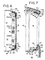
- the front wall is formed with a series of aligned slots 50 extending from edge to edge at a generally mid-level or centerline as best shown in FIGS. 4, 5 and 6.
- the front wall 48 includes a line of slots 52 extending vertically along opposite edges and joining the opposite ends of the center line of slots 50.
- the side edge slots 52 are joined with a pair of short oppositely inwardly directed lines of slots 54 positioned along an upper edge of the front wall 48.
- Inner end slots of the line of slots 54 are provided with an enlarged rounded aperture 55 as best shown in FIGS. 4 and 5, and similarly, along a lower edge of the front wall 48 of the reinforcing element 46, there is provided a pair of short oppositely inwardly directed lines of slots 56 joining the lower end of the side edge line of slots 52.
- Inner end slots of the line slots 56 are formed with an enlarged rounded aperture 57.
- a line of relatively wide slots 58 corresponding to an upper hinge axis of the container 10.
- a line of relatively wide lower edge slots 60 corresponding to a lower hinge axis of the container 10.
- the center line of slots 50, the upper line of slots 58 and the lower line of slots 60 are generally parallel of each other and identify lines of fracture in the front wall 34 of the front cover 32 of the air bag container 10 when the air bag 14 is rapidly deployed by inflation. These lines of intended fracture are shown in dotted line form on FIG.
- the upper line of slots 58 and lower line of slots 60 generally define elongated axes of hinges for supporting and retaining the upper and lower panels or doors 62 and 64 when the panels are fractured away from one another along the centerline 50 during deployment of the air bag 14. Moreover, fracture also occurs along the vertical lines of opposite edge slots 52 in the outer surface of the front wall 34.
- the air bag container 10 includes a pair of new and unique hinges 66 constructed from strips of tough, strong, flexible, resilient, wovenscrim material formed of resinous plastic fibers such as that sold under the trademark "NYLON".
- the scrim material is woven with an open weave as shown in FIG. 4 and is especially adapted for positively retaining the upper and lower panels or doors 62 and 64 to a fixed peripheral edge wall 72 of the front cover member 32 during and after deployment of the air bag 14 as shown in FIG. 7.
- the scrim material of the hinges 66 extends longitudinally between the enlarged apertures 55 along the upper hinge line 58 and between the enlarged apertures 57 along the lower hinge line 60.
- Each hinge 66 includes a relatively large size first section 66a adapted to be secured to either an upper panel 62 or lower panel 64 in the front wall 34 of the front cover member 32.
- the first hinge sections 66a are adapted to bear against the back side face of the front wall 48 of the reinforcing element 46 and because both the reinforcing element and the hinge material have a large area of open space, the plastic resin used in the injection molding process to form the front cover member 32 can flow through and bond together the first section 66a of each hinge 66 with the front wall 48 as the outer layer of resinous plastic material making up the front wall 34 of the front cover member 32 is molded-in-place.
- the hinges 66 also include second sections 66b initially secured in place by means of staples or the like 68 to a layer of open weave reinforcing tape 70 secured around the inside peripheral wall 72 of the reinforcing element 46 as best shown in FIGS. 4 and 6. Because both the hinge sections 66b and the tape 70 are made of open weave material, injection molding plastic resin can flow through and around these elements to positively secure the hinge sections 66b in a molded-in-place condition with the respective upper and lower walls 38 and 40 of the front cover member 32.
- Each hinge 66 is also provided with a pair of integral, folded over webs or hinge portions 66c and 66d, which web portions are arranged in overlying relationship with one another and with a first section 66a (FIGS. 4 and 6) before the injection of molded plastic material takes place.
- the overlying web portions 66c and 66d provide flexibility and strength to permit relatively wide, angular movement during opening of the upper panel 62 (approximately 270°, FIG. 7) and the lower panel 64 (approximately 180°, FIG. 7). Both hinges 66 thus positively secure the doors or panels 62 and 64 to the fixed side wall structure 36 of the front cover member 32 during and after deployment of the air bag 14.
- the panels are permanently secured to the peripheral fixed side wall 36 even though fracture of the front wall 34 into separate panels 62 and 64 has occurred and the panels have been rapidly pivoted along fold or hinge lines 58 and 68 during deployment of the air bag 14. This arrangement ensures that the air bag 14 itself is not punctured or cut during deployment and that the cover doors or panels 62 and 64 do not separate permanently and fly about or become dangerous projectiles with uncontrollable trajectories during rapid air bag deployment.
- strips of impervious tape or plastic material 74 are interposed between the folded over, overlying web portions 66c and 66d of each hinge 66 and between the overlying hinge portions 66d and the first sections 66a of each hinge 77 adjacent the respective panels or doors 62 and 64.
- the impervious strips of tape 74 prevent resin from filling in between the overlying webs of the open weave scrim material of the hinges 66 so that free pivotal movement along the fold lines 58, 58' and 60, 60' is achieved without any retarding action caused because of solidified resin.
- FIG. 3 illustrates a back side view of the front cover member 32 after the injection molding process has taken place
- the back surface of the cover member is provided with elongated indentations or grooves 50', 52', 54' 55', 56' and 57' which grooves provide for a reduced wall thickness overall of the molded plastic front cover member 32 along the lines of intended fracture.
- the inside grooves are positioned opposite and corresponding to the lines of slots 50, 52, 54, 55, 56 and 57 provided in the plastic reinforcing element 46.
- the resultant injection molded, resinous plastic structure is thus strong and stiff and provides a nice appearing front wall or surface 34 for the air bag container 10 mounted on a steering wheel 12 of a motor vehicle and at the same time concentric lines of stress to locate desired lines of fracture to ensure that rapid deployment of the air bag 14 can occur with minimal interference.
- FIG. 8 represents the pressure in the air bag 14 during a deployment thereof and it should be noted that initially the pressure is very high.
- the hinges 66 are strong, resilient and flexible to withstand this high stresss without failure and because the portions 66a and 66b of the hinges are molded-in-place exceptional holding power is provided. Moreover, the need for a metal reinforcing element or hinge is eliminated in the container 10 of the present invention.
Landscapes
- Engineering & Computer Science (AREA)
- Mechanical Engineering (AREA)
- Air Bags (AREA)
- Respiratory Apparatuses And Protective Means (AREA)
- Purses, Travelling Bags, Baskets, Or Suitcases (AREA)
- Superstructure Of Vehicle (AREA)
Applications Claiming Priority (2)
| Application Number | Priority Date | Filing Date | Title |
|---|---|---|---|
| FR9209829A FR2694530A1 (fr) | 1992-08-07 | 1992-08-07 | Conteneur pour coussinet de sécurité. |
| FR9209829 | 1992-08-07 |
Publications (2)
| Publication Number | Publication Date |
|---|---|
| EP0582443A1 true EP0582443A1 (fr) | 1994-02-09 |
| EP0582443B1 EP0582443B1 (fr) | 1996-12-04 |
Family
ID=9432720
Family Applications (1)
| Application Number | Title | Priority Date | Filing Date |
|---|---|---|---|
| EP93306020A Expired - Lifetime EP0582443B1 (fr) | 1992-08-07 | 1993-07-30 | Couvercle pour loger un coussin pneumatique destiné à un générateur de gaz à haute puissance et charnière pour celui-ci |
Country Status (10)
| Country | Link |
|---|---|
| US (1) | US5346249A (fr) |
| EP (1) | EP0582443B1 (fr) |
| JP (2) | JPH06171450A (fr) |
| AT (1) | ATE145868T1 (fr) |
| AU (1) | AU3983993A (fr) |
| CA (1) | CA2101470A1 (fr) |
| DE (1) | DE69306331T2 (fr) |
| FR (1) | FR2694530A1 (fr) |
| MX (1) | MX9303716A (fr) |
| ZA (1) | ZA934076B (fr) |
Cited By (11)
| Publication number | Priority date | Publication date | Assignee | Title |
|---|---|---|---|---|
| DE4437773C1 (de) * | 1994-10-24 | 1995-10-26 | Daimler Benz Ag | Instrumententafel mit einem integrierten, aufklappbaren Gassackdeckel |
| DE4425495A1 (de) * | 1994-07-19 | 1996-01-25 | Takata Europ Gmbh | Airbag-Anordnung |
| EP0695669A1 (fr) * | 1994-08-05 | 1996-02-07 | Morton International, Inc. | Système de sac gonflable avec un couvercle retenu par sangle |
| EP0761507A1 (fr) * | 1995-08-24 | 1997-03-12 | General Motors Corporation | Module de sac gonflable et volant de direction |
| US5658008A (en) * | 1994-07-19 | 1997-08-19 | Takata (Europe) Vehicle Safety Technology Gmbh | Airbag arrangement |
| DE19935625C2 (de) * | 1999-07-29 | 2003-12-04 | Ruetgers Kunststofftechnik Gmb | Gassackabdeckung |
| EP1393994A1 (fr) * | 2002-08-22 | 2004-03-03 | Peguform GmbH & Co. KG | Couvercle de module de sac gonflable comprenant un renforcement allégé en plastique |
| WO2009080616A1 (fr) * | 2007-12-20 | 2009-07-02 | Dsm Ip Assets B.V. | Conteneur de coussin de sécurité gonflable |
| DE102007008797B4 (de) * | 2007-02-22 | 2015-11-12 | Bayerische Motoren Werke Aktiengesellschaft | Fahrzeug mit einer Airbaganordnung |
| CN105196955A (zh) * | 2014-06-24 | 2015-12-30 | 福特全球技术公司 | 车辆安全气囊总成的模制的有效塑料组件 |
| EP3730354A1 (fr) * | 2019-04-24 | 2020-10-28 | Faurecia Intérieur Industrie | Système de coussin gonflable pour véhicule et procédé de fabrication du système de coussin gonflable |
Families Citing this family (25)
| Publication number | Priority date | Publication date | Assignee | Title |
|---|---|---|---|---|
| US5501485A (en) * | 1992-12-02 | 1996-03-26 | Larry J. Winget | Snap-on air bag cover |
| US5498026A (en) * | 1992-12-02 | 1996-03-12 | Larry J. Winget | Air bag cover having a hidden break seam |
| US5487557A (en) * | 1993-10-20 | 1996-01-30 | Larry J. Winget | Air bag cover having an applique fastened thereto and method of manufacturing same |
| US5429784A (en) * | 1993-12-06 | 1995-07-04 | Davidson Textron Inc. | Method for making a reinforced air bag door cover |
| US5836610A (en) * | 1994-05-31 | 1998-11-17 | Morton International, Inc. | Multiple level fluid fueled airbag inflator |
| US5803492A (en) * | 1994-05-31 | 1998-09-08 | Morton International, Inc. | Fuel containment for fluid fueled airbag inflators |
| JPH08230597A (ja) * | 1994-12-26 | 1996-09-10 | Toyoda Gosei Co Ltd | エアバッグ装置 |
| US5779266A (en) * | 1995-10-10 | 1998-07-14 | Morton International, Inc. | Fluid fueled inflator with flow reversal |
| US5636859A (en) * | 1995-11-09 | 1997-06-10 | General Motors Corporation | Air bag module assembly |
| US5857699A (en) * | 1997-02-25 | 1999-01-12 | Autoliv Asp, Inc. | Adaptive output fluid fueled airbag inflator |
| US6047984A (en) * | 1998-04-06 | 2000-04-11 | Larry J. Winget | Air bag cover and method of making same |
| US6402189B1 (en) | 2000-02-15 | 2002-06-11 | Textron Automotive Company, Inc | Airbag door and method for making same |
| JP3625756B2 (ja) * | 2000-09-19 | 2005-03-02 | ダイハツ工業株式会社 | エアバッグ装置のカバー構造 |
| FR2842472B1 (fr) * | 2002-07-17 | 2005-02-18 | Faurecia Interieur Ind | Ensemble de masquage d'un coussin gonflable de securite a organes de renfort et procede de realisation correspondants |
| US20040119267A1 (en) * | 2002-12-19 | 2004-06-24 | Lear Corporation | Natural fiber tether for an airbag system |
| US7014208B2 (en) * | 2003-03-21 | 2006-03-21 | Lear Corporation | Interior vehicle trim panel |
| US7140636B2 (en) * | 2003-05-07 | 2006-11-28 | Lear Corporation | Airbag support assembly for a vehicle instrument panel |
| US20050104338A1 (en) * | 2003-11-19 | 2005-05-19 | Quin Soderquist | Applique film airbag cover |
| US7291301B2 (en) * | 2003-12-09 | 2007-11-06 | International Automotive Components Group North America, Inc. | Method of manufacturing an airbag assembly and vehicle trim component |
| US7160404B2 (en) * | 2003-12-10 | 2007-01-09 | Lear Corporation | Method of manufacturing an airbag assembly and vehicle trim component |
| DE102006008564B4 (de) * | 2006-02-22 | 2009-06-10 | Peguform Gmbh | Luftsackführung mit Abdeckung |
| KR101240603B1 (ko) * | 2010-11-22 | 2013-03-06 | 현대모비스 주식회사 | 조수석 에어백 도어 |
| US8567814B2 (en) * | 2011-05-19 | 2013-10-29 | Faurecia Interior Systems, Inc. | Patterned weakening of airbag coverings |
| EP3670032A1 (fr) * | 2018-12-21 | 2020-06-24 | Aciturri Engineering S.L.U. | Procédé de production de pièces tridimensionnelles |
| KR102680264B1 (ko) * | 2020-01-10 | 2024-07-01 | 현대모비스 주식회사 | 스크림 일체형 에어백 도어 및 그 제조방법 |
Citations (10)
| Publication number | Priority date | Publication date | Assignee | Title |
|---|---|---|---|---|
| US3199913A (en) * | 1963-06-13 | 1965-08-10 | Gen Motors Corp | Vehicle body sunshade |
| US3551940A (en) * | 1968-08-19 | 1971-01-05 | Lilly Co Eli | Box hinge |
| US3767229A (en) * | 1971-12-30 | 1973-10-23 | R Cain | Inflatable dash-panel construction |
| US4183550A (en) * | 1977-12-29 | 1980-01-15 | Toyota Jidosha Kogyo Kabushiki Kaisha | Air bag holding means in an inflating type occupant restraint device |
| DE2848547A1 (de) * | 1978-11-09 | 1980-05-22 | Daimler Benz Ag | Nach unten aufklappbare abdeckung fuer ein gefaltet angeordnetes gaskissen |
| US4414705A (en) * | 1981-07-17 | 1983-11-15 | Ethyl Products Company | Overcenter hinge |
| US4968057A (en) * | 1989-12-11 | 1990-11-06 | Davidson Textron Inc. | Cover assembly for an airbag unit |
| DE4024189A1 (de) * | 1989-08-08 | 1991-02-14 | Toyoda Gosei Kk | Abdeckung fuer eine airbag-einheit |
| US5044663A (en) * | 1990-02-12 | 1991-09-03 | Solvay Automotive, Inc. | Blow molded airbag with fabric reinforcements |
| US5069477A (en) * | 1989-10-30 | 1991-12-03 | Toyoda Gosei Co., Ltd. | Pad for air bag device |
Family Cites Families (9)
| Publication number | Priority date | Publication date | Assignee | Title |
|---|---|---|---|---|
| US3656790A (en) * | 1970-10-12 | 1972-04-18 | William H Nienstedt | Vehicle pre-loaded impact-cushioning device |
| US3910595A (en) * | 1970-10-27 | 1975-10-07 | Rocket Research Corp | Aspirating apparatus and method for crash restraint system |
| GB1358364A (en) * | 1971-12-03 | 1974-07-03 | Daimler Benz Ag | Vehicle with automatically inflatable protective gas cushion |
| US3880447A (en) * | 1973-05-16 | 1975-04-29 | Rocket Research Corp | Crash restraint inflator for steering wheel assembly |
| DE2425659A1 (de) * | 1974-05-28 | 1975-12-11 | Audi Nsu Auto Union Ag | Sicherheitsvorrichtung mit einem aufblasbaren auffangbeutel in einem kraftfahrzeug |
| DE2524770A1 (de) * | 1975-06-04 | 1976-12-16 | Volkswagenwerk Ag | Sicherheitseinrichtung |
| JPS52116537A (en) * | 1976-03-26 | 1977-09-30 | Toyota Motor Corp | Expansion type passenger restricting device for automobile or the like |
| DE3011463A1 (de) * | 1980-03-25 | 1981-10-08 | Repa Feinstanzwerk Gmbh, 7071 Alfdorf | Vorrichtung in kraftfahrzeugen fuer die halterung von zum schutze der fahrzeuginsassen angeordneten luftsaecken |
| NL8400141A (nl) * | 1984-01-17 | 1985-08-16 | Philips Nv | Haarbehandelingsmiddel. |
-
1992
- 1992-08-07 FR FR9209829A patent/FR2694530A1/fr not_active Withdrawn
-
1993
- 1993-05-27 AU AU39839/93A patent/AU3983993A/en not_active Abandoned
- 1993-06-09 ZA ZA934076A patent/ZA934076B/xx unknown
- 1993-06-21 MX MX9303716A patent/MX9303716A/es unknown
- 1993-07-16 US US08/093,815 patent/US5346249A/en not_active Expired - Fee Related
- 1993-07-28 CA CA002101470A patent/CA2101470A1/fr not_active Abandoned
- 1993-07-30 DE DE69306331T patent/DE69306331T2/de not_active Expired - Fee Related
- 1993-07-30 EP EP93306020A patent/EP0582443B1/fr not_active Expired - Lifetime
- 1993-07-30 AT AT93306020T patent/ATE145868T1/de not_active IP Right Cessation
- 1993-08-06 JP JP5195961A patent/JPH06171450A/ja active Pending
-
1997
- 1997-03-03 JP JP1997001253U patent/JP3041401U/ja not_active Expired - Lifetime
Patent Citations (10)
| Publication number | Priority date | Publication date | Assignee | Title |
|---|---|---|---|---|
| US3199913A (en) * | 1963-06-13 | 1965-08-10 | Gen Motors Corp | Vehicle body sunshade |
| US3551940A (en) * | 1968-08-19 | 1971-01-05 | Lilly Co Eli | Box hinge |
| US3767229A (en) * | 1971-12-30 | 1973-10-23 | R Cain | Inflatable dash-panel construction |
| US4183550A (en) * | 1977-12-29 | 1980-01-15 | Toyota Jidosha Kogyo Kabushiki Kaisha | Air bag holding means in an inflating type occupant restraint device |
| DE2848547A1 (de) * | 1978-11-09 | 1980-05-22 | Daimler Benz Ag | Nach unten aufklappbare abdeckung fuer ein gefaltet angeordnetes gaskissen |
| US4414705A (en) * | 1981-07-17 | 1983-11-15 | Ethyl Products Company | Overcenter hinge |
| DE4024189A1 (de) * | 1989-08-08 | 1991-02-14 | Toyoda Gosei Kk | Abdeckung fuer eine airbag-einheit |
| US5069477A (en) * | 1989-10-30 | 1991-12-03 | Toyoda Gosei Co., Ltd. | Pad for air bag device |
| US4968057A (en) * | 1989-12-11 | 1990-11-06 | Davidson Textron Inc. | Cover assembly for an airbag unit |
| US5044663A (en) * | 1990-02-12 | 1991-09-03 | Solvay Automotive, Inc. | Blow molded airbag with fabric reinforcements |
Cited By (16)
| Publication number | Priority date | Publication date | Assignee | Title |
|---|---|---|---|---|
| DE4425495A1 (de) * | 1994-07-19 | 1996-01-25 | Takata Europ Gmbh | Airbag-Anordnung |
| US5658008A (en) * | 1994-07-19 | 1997-08-19 | Takata (Europe) Vehicle Safety Technology Gmbh | Airbag arrangement |
| US5762361A (en) * | 1994-07-19 | 1998-06-09 | Takata (Europe) Safety Technology Gmbh | Airbag arrangement |
| EP0695669A1 (fr) * | 1994-08-05 | 1996-02-07 | Morton International, Inc. | Système de sac gonflable avec un couvercle retenu par sangle |
| DE4437773C1 (de) * | 1994-10-24 | 1995-10-26 | Daimler Benz Ag | Instrumententafel mit einem integrierten, aufklappbaren Gassackdeckel |
| US5564733A (en) * | 1994-10-24 | 1996-10-15 | Mercedes-Benz Ag | Instrument panel having an integrated, swing-open air-bag cover |
| EP0761507A1 (fr) * | 1995-08-24 | 1997-03-12 | General Motors Corporation | Module de sac gonflable et volant de direction |
| DE19935625C2 (de) * | 1999-07-29 | 2003-12-04 | Ruetgers Kunststofftechnik Gmb | Gassackabdeckung |
| EP1393994A1 (fr) * | 2002-08-22 | 2004-03-03 | Peguform GmbH & Co. KG | Couvercle de module de sac gonflable comprenant un renforcement allégé en plastique |
| DE102007008797B4 (de) * | 2007-02-22 | 2015-11-12 | Bayerische Motoren Werke Aktiengesellschaft | Fahrzeug mit einer Airbaganordnung |
| WO2009080616A1 (fr) * | 2007-12-20 | 2009-07-02 | Dsm Ip Assets B.V. | Conteneur de coussin de sécurité gonflable |
| EA016860B1 (ru) * | 2007-12-20 | 2012-08-30 | ДСМ АйПи АССЕТС Б.В. | Контейнер воздушной подушки безопасности |
| US8641080B2 (en) | 2007-12-20 | 2014-02-04 | Dsm Ip Assets B.V. | Air bag container |
| CN105196955A (zh) * | 2014-06-24 | 2015-12-30 | 福特全球技术公司 | 车辆安全气囊总成的模制的有效塑料组件 |
| EP3730354A1 (fr) * | 2019-04-24 | 2020-10-28 | Faurecia Intérieur Industrie | Système de coussin gonflable pour véhicule et procédé de fabrication du système de coussin gonflable |
| US11351944B2 (en) | 2019-04-24 | 2022-06-07 | Faurecia Interieur Industrie | Airbag system for a vehicle and method for manufacturing the airbag system |
Also Published As
| Publication number | Publication date |
|---|---|
| ZA934076B (en) | 1994-01-10 |
| EP0582443B1 (fr) | 1996-12-04 |
| DE69306331D1 (de) | 1997-01-16 |
| CA2101470A1 (fr) | 1994-02-08 |
| AU3983993A (en) | 1994-02-10 |
| ATE145868T1 (de) | 1996-12-15 |
| JP3041401U (ja) | 1997-09-19 |
| MX9303716A (es) | 1994-02-28 |
| FR2694530A1 (fr) | 1994-02-11 |
| US5346249A (en) | 1994-09-13 |
| JPH06171450A (ja) | 1994-06-21 |
| DE69306331T2 (de) | 1997-04-03 |
Similar Documents
| Publication | Publication Date | Title |
|---|---|---|
| US5346249A (en) | Airbag cover hinge reinforcement for high performance inflator | |
| EP0363986B1 (fr) | Fermeture à deux battants pour ouverture de déploiement de sac d'air | |
| CA2043984C (fr) | Tableau de bord avec volet de coussin a air dissimule | |
| AU687226B2 (en) | Method and apparatus for vehicle trim panel having hidden air bag door | |
| EP0629527B1 (fr) | Fermeture pour sac d'air | |
| US5322324A (en) | Cover for an inflatable air bag housing | |
| US6092835A (en) | Automotive instrument panel having an integral airbag | |
| US5398968A (en) | Air bag module including folded air bag | |
| EP0695669A1 (fr) | Système de sac gonflable avec un couvercle retenu par sangle | |
| US5474324A (en) | Tethered cover airbag system | |
| CA2117133A1 (fr) | Fermeture pour sac gonflable | |
| US5520409A (en) | Cover retention in occupant restraint installations | |
| US5340149A (en) | Door assembly with integral tether | |
| US5527062A (en) | Air bag apparatus for impact protection | |
| JP3039857U (ja) | エアバッグ展開用開口のための閉鎖要素 | |
| US5460403A (en) | Inflatable air bag module | |
| US5116079A (en) | Instrument panel air bag cover door | |
| CN112208478A (zh) | 车辆安全气囊总成及相关的成型方法 | |
| US5722684A (en) | Hinged module cover | |
| US5374079A (en) | Closure for air bag assembly | |
| US6290252B1 (en) | Air bag module | |
| JPH10211831A (ja) | エアバッグドア部を一体に有するインストルメントパネル | |
| JP3792297B2 (ja) | エアバッグ組立体のための閉鎖組立体 | |
| JPH0747905A (ja) | 自動車用エアバッグドアの構造 | |
| JPH06278558A (ja) | エアバッグ装置 |
Legal Events
| Date | Code | Title | Description |
|---|---|---|---|
| PUAI | Public reference made under article 153(3) epc to a published international application that has entered the european phase |
Free format text: ORIGINAL CODE: 0009012 |
|
| AK | Designated contracting states |
Kind code of ref document: A1 Designated state(s): AT BE CH DE DK ES FR GB IT LI NL SE |
|
| 17P | Request for examination filed |
Effective date: 19940222 |
|
| 17Q | First examination report despatched |
Effective date: 19950405 |
|
| GRAH | Despatch of communication of intention to grant a patent |
Free format text: ORIGINAL CODE: EPIDOS IGRA |
|
| GRAH | Despatch of communication of intention to grant a patent |
Free format text: ORIGINAL CODE: EPIDOS IGRA |
|
| GRAA | (expected) grant |
Free format text: ORIGINAL CODE: 0009210 |
|
| AK | Designated contracting states |
Kind code of ref document: B1 Designated state(s): AT BE CH DE DK ES FR GB IT LI NL SE |
|
| PG25 | Lapsed in a contracting state [announced via postgrant information from national office to epo] |
Ref country code: NL Free format text: LAPSE BECAUSE OF FAILURE TO SUBMIT A TRANSLATION OF THE DESCRIPTION OR TO PAY THE FEE WITHIN THE PRESCRIBED TIME-LIMIT Effective date: 19961204 Ref country code: LI Effective date: 19961204 Ref country code: ES Free format text: THE PATENT HAS BEEN ANNULLED BY A DECISION OF A NATIONAL AUTHORITY Effective date: 19961204 Ref country code: DK Effective date: 19961204 Ref country code: CH Effective date: 19961204 Ref country code: BE Effective date: 19961204 Ref country code: AT Effective date: 19961204 |
|
| REF | Corresponds to: |
Ref document number: 145868 Country of ref document: AT Date of ref document: 19961215 Kind code of ref document: T |
|
| REF | Corresponds to: |
Ref document number: 69306331 Country of ref document: DE Date of ref document: 19970116 |
|
| ET | Fr: translation filed | ||
| ITF | It: translation for a ep patent filed | ||
| PG25 | Lapsed in a contracting state [announced via postgrant information from national office to epo] |
Ref country code: SE Effective date: 19970304 |
|
| NLV1 | Nl: lapsed or annulled due to failure to fulfill the requirements of art. 29p and 29m of the patents act | ||
| REG | Reference to a national code |
Ref country code: CH Ref legal event code: PL |
|
| PLBE | No opposition filed within time limit |
Free format text: ORIGINAL CODE: 0009261 |
|
| STAA | Information on the status of an ep patent application or granted ep patent |
Free format text: STATUS: NO OPPOSITION FILED WITHIN TIME LIMIT |
|
| 26N | No opposition filed | ||
| REG | Reference to a national code |
Ref country code: GB Ref legal event code: IF02 |
|
| PGFP | Annual fee paid to national office [announced via postgrant information from national office to epo] |
Ref country code: FR Payment date: 20040720 Year of fee payment: 12 |
|
| PGFP | Annual fee paid to national office [announced via postgrant information from national office to epo] |
Ref country code: GB Payment date: 20040721 Year of fee payment: 12 |
|
| PG25 | Lapsed in a contracting state [announced via postgrant information from national office to epo] |
Ref country code: IT Free format text: LAPSE BECAUSE OF NON-PAYMENT OF DUE FEES;WARNING: LAPSES OF ITALIAN PATENTS WITH EFFECTIVE DATE BEFORE 2007 MAY HAVE OCCURRED AT ANY TIME BEFORE 2007. THE CORRECT EFFECTIVE DATE MAY BE DIFFERENT FROM THE ONE RECORDED. Effective date: 20050730 Ref country code: GB Free format text: LAPSE BECAUSE OF NON-PAYMENT OF DUE FEES Effective date: 20050730 |
|
| PGFP | Annual fee paid to national office [announced via postgrant information from national office to epo] |
Ref country code: DE Payment date: 20050831 Year of fee payment: 13 |
|
| GBPC | Gb: european patent ceased through non-payment of renewal fee |
Effective date: 20050730 |
|
| PG25 | Lapsed in a contracting state [announced via postgrant information from national office to epo] |
Ref country code: FR Free format text: LAPSE BECAUSE OF NON-PAYMENT OF DUE FEES Effective date: 20060331 |
|
| REG | Reference to a national code |
Ref country code: FR Ref legal event code: ST Effective date: 20060331 |
|
| PG25 | Lapsed in a contracting state [announced via postgrant information from national office to epo] |
Ref country code: DE Free format text: LAPSE BECAUSE OF NON-PAYMENT OF DUE FEES Effective date: 20070201 |