EP0583016A2 - Tintenstrahlaufzeichnungsvorrichtung - Google Patents
Tintenstrahlaufzeichnungsvorrichtung Download PDFInfo
- Publication number
- EP0583016A2 EP0583016A2 EP93116572A EP93116572A EP0583016A2 EP 0583016 A2 EP0583016 A2 EP 0583016A2 EP 93116572 A EP93116572 A EP 93116572A EP 93116572 A EP93116572 A EP 93116572A EP 0583016 A2 EP0583016 A2 EP 0583016A2
- Authority
- EP
- European Patent Office
- Prior art keywords
- recording
- ink
- discharge
- head
- unit
- Prior art date
- Legal status (The legal status is an assumption and is not a legal conclusion. Google has not performed a legal analysis and makes no representation as to the accuracy of the status listed.)
- Granted
Links
Images













Classifications
-
- B—PERFORMING OPERATIONS; TRANSPORTING
- B41—PRINTING; LINING MACHINES; TYPEWRITERS; STAMPS
- B41J—TYPEWRITERS; SELECTIVE PRINTING MECHANISMS, i.e. MECHANISMS PRINTING OTHERWISE THAN FROM A FORME; CORRECTION OF TYPOGRAPHICAL ERRORS
- B41J2/00—Typewriters or selective printing mechanisms characterised by the printing or marking process for which they are designed
- B41J2/005—Typewriters or selective printing mechanisms characterised by the printing or marking process for which they are designed characterised by bringing liquid or particles selectively into contact with a printing material
- B41J2/01—Ink jet
- B41J2/135—Nozzles
- B41J2/165—Prevention or detection of nozzle clogging, e.g. cleaning, capping or moistening for nozzles
- B41J2/16585—Prevention or detection of nozzle clogging, e.g. cleaning, capping or moistening for nozzles for paper-width or non-reciprocating print heads
- B41J2/16588—Print heads movable towards the cleaning unit
-
- B—PERFORMING OPERATIONS; TRANSPORTING
- B41—PRINTING; LINING MACHINES; TYPEWRITERS; STAMPS
- B41J—TYPEWRITERS; SELECTIVE PRINTING MECHANISMS, i.e. MECHANISMS PRINTING OTHERWISE THAN FROM A FORME; CORRECTION OF TYPOGRAPHICAL ERRORS
- B41J11/00—Devices or arrangements of selective printing mechanisms, e.g. ink-jet printers or thermal printers, for supporting or handling copy material in sheet or web form
- B41J11/009—Detecting type of paper, e.g. by automatic reading of a code that is printed on a paper package or on a paper roll or by sensing the grade of translucency of the paper
-
- B—PERFORMING OPERATIONS; TRANSPORTING
- B41—PRINTING; LINING MACHINES; TYPEWRITERS; STAMPS
- B41J—TYPEWRITERS; SELECTIVE PRINTING MECHANISMS, i.e. MECHANISMS PRINTING OTHERWISE THAN FROM A FORME; CORRECTION OF TYPOGRAPHICAL ERRORS
- B41J11/00—Devices or arrangements of selective printing mechanisms, e.g. ink-jet printers or thermal printers, for supporting or handling copy material in sheet or web form
- B41J11/0095—Detecting means for copy material, e.g. for detecting or sensing presence of copy material or its leading or trailing end
-
- B—PERFORMING OPERATIONS; TRANSPORTING
- B41—PRINTING; LINING MACHINES; TYPEWRITERS; STAMPS
- B41J—TYPEWRITERS; SELECTIVE PRINTING MECHANISMS, i.e. MECHANISMS PRINTING OTHERWISE THAN FROM A FORME; CORRECTION OF TYPOGRAPHICAL ERRORS
- B41J2/00—Typewriters or selective printing mechanisms characterised by the printing or marking process for which they are designed
- B41J2/005—Typewriters or selective printing mechanisms characterised by the printing or marking process for which they are designed characterised by bringing liquid or particles selectively into contact with a printing material
- B41J2/01—Ink jet
- B41J2/135—Nozzles
- B41J2/165—Prevention or detection of nozzle clogging, e.g. cleaning, capping or moistening for nozzles
- B41J2/16517—Cleaning of print head nozzles
- B41J2/1652—Cleaning of print head nozzles by driving a fluid through the nozzles to the outside thereof, e.g. by applying pressure to the inside or vacuum at the outside of the print head
-
- B—PERFORMING OPERATIONS; TRANSPORTING
- B41—PRINTING; LINING MACHINES; TYPEWRITERS; STAMPS
- B41J—TYPEWRITERS; SELECTIVE PRINTING MECHANISMS, i.e. MECHANISMS PRINTING OTHERWISE THAN FROM A FORME; CORRECTION OF TYPOGRAPHICAL ERRORS
- B41J29/00—Details of, or accessories for, typewriters or selective printing mechanisms not otherwise provided for
- B41J29/17—Cleaning arrangements
-
- B—PERFORMING OPERATIONS; TRANSPORTING
- B41—PRINTING; LINING MACHINES; TYPEWRITERS; STAMPS
- B41J—TYPEWRITERS; SELECTIVE PRINTING MECHANISMS, i.e. MECHANISMS PRINTING OTHERWISE THAN FROM A FORME; CORRECTION OF TYPOGRAPHICAL ERRORS
- B41J2/00—Typewriters or selective printing mechanisms characterised by the printing or marking process for which they are designed
- B41J2/005—Typewriters or selective printing mechanisms characterised by the printing or marking process for which they are designed characterised by bringing liquid or particles selectively into contact with a printing material
- B41J2/01—Ink jet
- B41J2/135—Nozzles
- B41J2/165—Prevention or detection of nozzle clogging, e.g. cleaning, capping or moistening for nozzles
- B41J2/16517—Cleaning of print head nozzles
- B41J2/16535—Cleaning of print head nozzles using wiping constructions
- B41J2/16541—Means to remove deposits from wipers or scrapers
-
- B—PERFORMING OPERATIONS; TRANSPORTING
- B41—PRINTING; LINING MACHINES; TYPEWRITERS; STAMPS
- B41J—TYPEWRITERS; SELECTIVE PRINTING MECHANISMS, i.e. MECHANISMS PRINTING OTHERWISE THAN FROM A FORME; CORRECTION OF TYPOGRAPHICAL ERRORS
- B41J2/00—Typewriters or selective printing mechanisms characterised by the printing or marking process for which they are designed
- B41J2/005—Typewriters or selective printing mechanisms characterised by the printing or marking process for which they are designed characterised by bringing liquid or particles selectively into contact with a printing material
- B41J2/01—Ink jet
- B41J2/17—Ink jet characterised by ink handling
- B41J2/1707—Conditioning of the inside of ink supply circuits, e.g. flushing during start-up or shut-down
-
- B—PERFORMING OPERATIONS; TRANSPORTING
- B41—PRINTING; LINING MACHINES; TYPEWRITERS; STAMPS
- B41J—TYPEWRITERS; SELECTIVE PRINTING MECHANISMS, i.e. MECHANISMS PRINTING OTHERWISE THAN FROM A FORME; CORRECTION OF TYPOGRAPHICAL ERRORS
- B41J2202/00—Embodiments of or processes related to ink-jet or thermal heads
- B41J2202/01—Embodiments of or processes related to ink-jet heads
- B41J2202/12—Embodiments of or processes related to ink-jet heads with ink circulating through the whole print head
Definitions
- Non-impact recording methods are recently attracting attention due to their advantage that the noise level at the recording operation is negligibly low.
- the ink jet recording is particularly promising because of the possibility of high speed recording and the capability of recording on ordinary paper without particular fixing treatment.
- the recording head employed in the ink jet recording apparatus is generally provided with a small liquid discharge port (orifice), a liquid path, an energy applying part formed in said liquid path, and energy generating means for generating energy for liquid droplet formation, to be applied to the liquid present in said energy applying part.
- the present inventors have made numerical designs of a full-line recording head consisting of a long single bead for satisfying the requirements of compactization of the apparatus, stable image formation and high speed recording, but have been unable, in any design, to avoid the drawbacks related to the means for recovering the discharge function of the recording head.
- Still another object of the present invention is to provide an ink jet recording apparatus in which a recording head unit and a recovery unit are integrated to achieve an improved precision of positioning with respect to the apparatus.
- Still another object of the present invention is to provide a structure that is also applicable to the serial type apparatus as will be explained in the following.
- the solenoid valve 1662 is closed and the pump 1659 is activated to pressurize the recording liquid to the common liquid chamber 1652 through the circulating pipe 1661, thereby discharging the recording liquid from the discharge ports 1653 together with the discharge of bubbles.
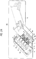
- Figs. 2A and 2B are partial cross-sectional views of the printer unit of an ink jet recording apparatus of the present invention.
- Ink jet recording heads 1C, 1M, 1Y, 1Bk respectively receiving inks of cyan, magenta, yellow and black are precisely fixed in a head block 6, with a level of parallelism and a mutual distance with a desired precision.
- Ink absorbing members 3C, 3M, 3Y, 3Bk In the vicinity of discharge ports of said heads 1C, 1M, 1Y, 1Bk there are provided ink absorbing members 3C, 3M, 3Y, 3Bk, corresponding to the discharge ports of said recording heads.
- the recovery reservoir 2 is provided at the bottom thereof with an ink exhaust opening, whereby the inks discharged from the recording heads 1C, 1M, 1Y, 1Bk, then absorbed by the ink absorbing members, 3C, 3M, 3Y, 3Bk and recovered therefrom is guided to an unrepresented used ink tank, through an unrepresented ink hose.
- Fig. 2B is a partial cross-sectional view showing the recording heads in the image recording state.
- the recovery reservoir 2 is moved from the state in Fig. 2A to the retracted position shown by chain lines, the recording heads rotate to a horizontal position as shown in Fig. 2B.
- the ink is discharged, in response to the image recording signal, from the recording heads, thereby forming an image on a recording sheet transported at a desired distance from the discharge face P of the recording heads.
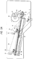
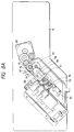
- a cap driving motor 60 is transmitted through gears 61 - 64 to a rack 65, and, further through members 66, 67, to a cap driving slide arm 68 slidable along slide pins 72.
- the reciprocating motion of said slide arm 68 is converted, by arms 69, into a vertical movement of the absorbing member guide 7.
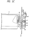
- the squeezing mechanism is activated when the ink absorbing members 3 are separated from the discharge faces of the recording heads, and the position of the squeezing mechanism is detected by a microswitch 87 engaging with and detecting the rotation of the cam 79.
- a unit operation of squeezing consists of a revolution of the cam.
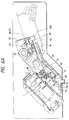
- the ink absorbing members 3 of which absorbing power is refreshed by said squeezing operation are again brought into discharge face of the heads, thereby achieving complete cleaning.
- the sheet advances to the fixing/exhaust unit 307 and is transferred from the conveyor belt 101 to a guide 213 by so-called curvature separation i which the driving roller 102 has a relatively small diameter and the sheet is separated spontaneously by the rigidity thereof.
- the diameter of the driving roller 102 is so selected that the moving distance of the surface of the conveyor belt 101 which is friction driven by said roller is equal to the distance between the discharge ports of the first head 1C and the fourth head 1Bk. This is to prevent possible aberration in the registration of images in case an eccentricity exists in the driving roller 102.
- the surface of the conveyor belt 101 is moved by a distance between the discharge ports of immediately neighboring recording heads by a revolution of the driving roller, but the diameter of the driving roller 102 cannot be made too small in consideration of the mechanical strength.
- said roller has to be inevitably large, eventually leading to the bulkiness of the apparatus, because the distance is tripled.
- there is considered the distance between the first and fourth heads as said distance is largest among the heads and involves most the factors giving rise to errors in the registration.
- this is not limitative, and there may be adopted the distance between the first and third heads or between the immediately neighboring heads. In any case, however, certain concentration is necessary on the relationship between the diameter of the driving roller and the distance between the recording heads.
- the above-mentioned fixing means is not required for the coated paper, since, as explained before, the ink is rapidly absorbed therein.
- the first mode for plain paper is preferential, and the fixing means is energized unless the second mode for coated paper is selected by the operator. It is therefore passible to avoid such drawback as the transfer of ink onto the exhaust rollers 211, causing smears on other recording sheets, even when an image to be printed on a coated paper is printed on a plain paper by mistake.
- the present embodiment also has a third mode for printing on an overhead projector (OHP) film.
- OHP overhead projector
- the OHP sheet to be employed in the present embodiment has a coating similar to that on the coated paper, there will result ink oozing or ink flow if the printing is repeated in the same place within a short period.
- the complete ink absorption into the coated layer requires a long time, so that the image may be perturbed or transferred if the formed image touches something else within a short time after image formation.
- the next image formation is delayed for achieving complete ink absorption, and to prevent the image from any contact after the image formation, in order to avoid the ink transfer. It is also possible to use fixing means in such period.
- the sheet transport speed from the sheet feed unit 303 to the registration rollers 415, 416, speed of the conveyor belt of the unit 304, and the speed of the exhaust rollers 211, 212 are all reduced as explained above, and the heating members 200, 201 and the fan 203 are turned on with the timing as in the first mode to assist the image fixation.
- the transporting speed in the sheet exhaust unit In the usual structure, there can be formed a loop in the sheet between the belt 101 and the rollers 211, 212 in order not to affect the transporting speed of said belt, as in the aforementioned relation between the registration rollers and the conveyor belt.
- said loop formation in this part significantly deteriorate the fixing effect since the sheet can no longer proceed along the support member 202. Consequently, in the present embodiment, the transporting speed of the exhaust rollers 211, 212 is selected larger than that of the belt 101, thereby preventing the loop formation.
- the surface of the support member 202 of the heating member 200 is positioned slightly higher than a plane connecting the surface of the belt 101 and the nip of the exhaust rollers 211, 212, whereby the sheet is transported securely along the surface of the support member 202 once the front end of the sheet is pinched between the rollers 211, 212.
- the transporting power of said rollers 211, 212 is adequately controlled so as not to exceed that of the belt 101. This is achieved by forming naps of nylon fibers on the surface of the roller 211 coming into contact with the image bearing face of the sheet, thereby reducing the friction and also serving to prevent the ink offsetting, and by forming the roller 212 with a resin such as polyacetal resin.
- a fluctuation in the transporting speed of said unit 304 not only induces an elongation or a contraction of the recorded image, but also results in an aberration of image registration or an uneven color in an image formed by super-position of inks, such as a color image. Therefore the precision of movement of the conveyor belt 101 has to be satisfactorily controlled by giving sufficient attention to the driving source for the driving roller 102, diameter thereof and thickness of the belt 101. Consideration has also to be given to any other factor giving perturbation to the transport unit 405 and enhancing said fluctuation.
- said belt 101 is pushed by the sheet because the transporting speed of the registration rollers 415, 416 is faster than that of the belt 101, and said pushing force affects the uniformity of transporting speed thereof, eventually causing an unevenness in color or an aberration in the registration of images as explained above if a preceding sheet is under printing.
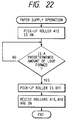
- the present embodiment employs such a sequence, in the continuous image recording, as to transfer the succeeding sheet onto the conveyor belt 101 after the rear end of the preceding sheet passes through the fourth recording head, so that the transfer of the succeeding sheet onto the belt 101 does not take place during the printing operation for the preceding sheet.
- timer means which activates the registration rollers 415, 416 by calculating the passing time of the rear end of sheet through the fourth recording head, in consideration of the longitudinal size of the transported sheet.
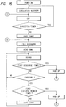
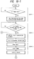
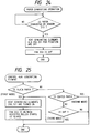
- a step 5 therein represents the repetition of the recording operation for the predetermined number of sheets.
- the idle discharge operation in response to the entry of the recording start signal, there are conducted the idle discharge operation, head-down operation and printing operation.
- the recording heads are lifted up for effecting idle discharge, and then lowered again to continue the printing operation.
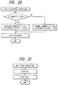
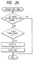
- Said first discharge timer effects the idle discharge at a predetermined time from the preceding idle discharge, in order to prevent discharge failure in the nozzles which are not used in the printing operation. This operation is to rectify slight discharge failure by the idle discharge, and is repeated at an interval of the order of minutes.
- the head-down state is maintained for the duration of the first discharge timer, awaiting the entry of the next recording start signal.
- the idle ink discharge for preventing the discharge failure of the recording heads is conducted onto the conveyor belt between the recording sheets, whereby said idle discharge can be conducted without interruption of the recording operation.
- Said first discharge remaining-time timer measures a time corresponding to the difference obtained by subtracting the time from the preceding idle discharge to the end of image recording, from the time of said first discharge timer, but, in practice, said time is selected somewhat shorter than said difference in consideration of the fact that the ink dries more easily as the heads are in the uncapped down state.
- said recording head unit is rendered capable of movement by rotation, and the aperture in such rotated state is positioned at the upstream side in the transporting direction of the recording material, whereby provided are advantages of protection of the discharge face of the recording head at the jamming of said recording material, ease of disposal of such jammed recording material, and prevention of drying or adhesion of ink on said discharge face, caused by the heat of the fixing unit which is usually positioned at the downstream side.
- said ink jet recording apparatus is provided with the ink absorbing members, means for attaching or separating said absorbing members to or from the discharge faces of the recording head, squeezing means for the absorbing members, means for preventing mixing of absorbed inks, means for preventing drying of the discharge faces of the recording head, and means for wiping said discharge faces, whereby stable ink discharge from the discharge ports of the recording head is ensured, thus preventing defective discharge, including discharge failure, and providing an image of high quality. Also there is provided an apparatus with a recording head of high reliability, high durability and long service life.
- said ink jet recording apparatus is provided with the recovery system, in which the head wiping means is operated in relation to the separating operation of the ink absorbing members from the discharge faces of the recording head, whereby the cleaning of said discharge faces and the recovery of defective nozzles can be achieved rapidly and efficiently, so that the recovery operation can be done in a shorter time and in more effective manner.
- the recording head, the supporting and moving means therefor, the head recovery system and the moving means therefor are constructed as an integral unit which is detachably mounted in the main body, whereby the entire apparatus can be compactized. Also such unit structure provides an advantage of maintenance-free apparatus.
- an ink jet recording apparatus capable of recovery operation of the ink jet recording head in secure manner.
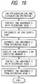
- the apparatus is provided with an endless belt for transporting a recording sheet by electrostatic attraction; a charger for the endless belt; a cleaner for the endless belt; a recording head unit with plural full-line ink jet heads; a recovery unit having a cleaning blade and an ink absorbing member movable between a recovery position and a stand-by position; and a mechanism for moving the head unit to a recording position, a recovery position or a recovery unit introducing position and moving the recovery unit in relation to the recording head unit; in which the head unit, recovery unit and moving mechanism are integrated as a detachable unit.
Landscapes
- Ink Jet (AREA)
Applications Claiming Priority (13)
| Application Number | Priority Date | Filing Date | Title |
|---|---|---|---|
| JP33475388A JP2733275B2 (ja) | 1988-12-30 | 1988-12-30 | 画像記録装置 |
| JP331039/88 | 1988-12-30 | ||
| JP63334754A JP2733276B2 (ja) | 1988-12-30 | 1988-12-30 | インクジェット記録装置 |
| JP63334747A JP2728914B2 (ja) | 1988-12-30 | 1988-12-30 | インクジェット記録装置 |
| JP63334755A JP2733277B2 (ja) | 1988-12-30 | 1988-12-30 | インクジェット記録装置 |
| JP334753/88 | 1988-12-30 | ||
| JP334754/88 | 1988-12-30 | ||
| JP334755/88 | 1988-12-30 | ||
| JP33103988A JPH02179752A (ja) | 1988-12-30 | 1988-12-30 | インクジェット記録装置 |
| JP331040/88 | 1988-12-30 | ||
| JP63331040A JP2728913B2 (ja) | 1988-12-30 | 1988-12-30 | インクジェット記録装置 |
| JP334747/88 | 1988-12-30 | ||
| EP89124077A EP0376309B1 (de) | 1988-12-30 | 1989-12-28 | Tintenstrahlaufzeichnungsvorrichtung |
Related Parent Applications (2)
| Application Number | Title | Priority Date | Filing Date |
|---|---|---|---|
| EP89124077A Division EP0376309B1 (de) | 1988-12-30 | 1989-12-28 | Tintenstrahlaufzeichnungsvorrichtung |
| EP89124077.2 Division | 1989-12-28 |
Publications (3)
| Publication Number | Publication Date |
|---|---|
| EP0583016A2 true EP0583016A2 (de) | 1994-02-16 |
| EP0583016A3 EP0583016A3 (de) | 1994-04-06 |
| EP0583016B1 EP0583016B1 (de) | 1997-09-10 |
Family
ID=27554628
Family Applications (2)
| Application Number | Title | Priority Date | Filing Date |
|---|---|---|---|
| EP89124077A Expired - Lifetime EP0376309B1 (de) | 1988-12-30 | 1989-12-28 | Tintenstrahlaufzeichnungsvorrichtung |
| EP93116572A Expired - Lifetime EP0583016B1 (de) | 1988-12-30 | 1989-12-28 | Tintenstrahlaufzeichnungsvorrichtung |
Family Applications Before (1)
| Application Number | Title | Priority Date | Filing Date |
|---|---|---|---|
| EP89124077A Expired - Lifetime EP0376309B1 (de) | 1988-12-30 | 1989-12-28 | Tintenstrahlaufzeichnungsvorrichtung |
Country Status (4)
| Country | Link |
|---|---|
| US (1) | US5055861A (de) |
| EP (2) | EP0376309B1 (de) |
| DE (2) | DE68923861T2 (de) |
| ES (1) | ES2076197T3 (de) |
Cited By (4)
| Publication number | Priority date | Publication date | Assignee | Title |
|---|---|---|---|---|
| WO1996015908A1 (en) * | 1994-11-21 | 1996-05-30 | Techniku B.V. | Cleaning and sealing station for a printing head |
| WO2004106074A1 (en) * | 2003-05-24 | 2004-12-09 | Hewlett-Packard Development Company, L.P. | Media electrostatic hold down and conductive heating assembly |
| US6997549B2 (en) | 2004-02-26 | 2006-02-14 | Hewlett-Packard Development Company, L.P. | Media hold down system |
| EP2168776A3 (de) * | 2008-09-26 | 2010-11-24 | Brother Kogyo Kabushiki Kaisha | Bildaufzeichnungsvorrichtung |
Families Citing this family (52)
| Publication number | Priority date | Publication date | Assignee | Title |
|---|---|---|---|---|
| US5262872A (en) * | 1985-03-28 | 1993-11-16 | Canon Kabushiki Kaisha | Image forming apparatus with means for error detection |
| EP0578331B1 (de) * | 1989-09-18 | 1997-12-29 | Canon Kabushiki Kaisha | Methode zum Füllen einer Tintenpatrone für Tintenstrahlaufzeichnungsgeräte |
| EP0445526B1 (de) * | 1990-02-02 | 1995-05-24 | Canon Kabushiki Kaisha | Tintenstrahl-Aufzeichnungsgerät |
| ES2073670T3 (es) * | 1990-02-02 | 1995-08-16 | Canon Kk | Aparato para la impresion por chorros de tinta y cabezal para la impresion por chorros de tinta. |
| US5225853A (en) * | 1990-02-02 | 1993-07-06 | Canon Kabushiki Kaisha | Recording apparatus with conveyor cleaning mechanism |
| ES2053215T3 (es) * | 1990-02-13 | 1994-07-16 | Canon Kk | Aparato de impresion por chorros de tinta. |
| EP0442471B1 (de) * | 1990-02-13 | 1996-01-03 | Canon Kabushiki Kaisha | Tintenstrahlaufzeichnungsgerät |
| EP0442470B1 (de) * | 1990-02-13 | 1997-11-19 | Canon Kabushiki Kaisha | Farbstrahlaufzeichnungsvorrichtung |
| JP2816217B2 (ja) * | 1990-02-21 | 1998-10-27 | キヤノン株式会社 | 記録装置 |
| JP2891796B2 (ja) * | 1990-04-17 | 1999-05-17 | キヤノン株式会社 | 被記録材を搬送するための搬送装置、および、その搬送装置を備える記録装置 |
| JP3014815B2 (ja) * | 1990-08-31 | 2000-02-28 | キヤノン株式会社 | インクジェット記録装置 |
| JP2955384B2 (ja) * | 1991-04-26 | 1999-10-04 | キヤノン株式会社 | 画像記録装置 |
| JP3016924B2 (ja) * | 1991-10-02 | 2000-03-06 | キヤノン株式会社 | 記録装置 |
| US5701146A (en) * | 1991-10-18 | 1997-12-23 | Canon Kabushiki Kaisha | Ink head recovery method and apparatus |
| US6116728A (en) * | 1992-02-26 | 2000-09-12 | Canon Kabushiki Kaisha | Ink jet recording method and apparatus and recorded matter |
| CN1096943C (zh) | 1992-02-26 | 2002-12-25 | 佳能株式会社 | 喷墨织物印刷方法及其印刷得到的材料 |
| US5329295A (en) * | 1992-05-01 | 1994-07-12 | Hewlett-Packard Company | Print zone heater screen for thermal ink-jet printer |
| US5456543A (en) * | 1992-05-01 | 1995-10-10 | Hewlett-Packard Company | Printer motor drive with backlash control system |
| US5296873A (en) * | 1992-05-01 | 1994-03-22 | Hewlett-Packard Company | Airflow system for thermal ink-jet printer |
| US5399039A (en) * | 1992-05-01 | 1995-03-21 | Hewlett-Packard Company | Ink-jet printer with precise print zone media control |
| EP0568181B1 (de) * | 1992-05-01 | 1997-05-28 | Hewlett-Packard Company | Wärme-Tintenstrahldrucker mit einem Heizelement, dem variable Wärmeenergie für unterschiedliche Druckmedien zugeführt wird |
| US5287123A (en) * | 1992-05-01 | 1994-02-15 | Hewlett-Packard Company | Preheat roller for thermal ink-jet printer |
| US5406316A (en) * | 1992-05-01 | 1995-04-11 | Hewlett-Packard Company | Airflow system for ink-jet printer |
| DE69304774T2 (de) * | 1992-05-01 | 1997-02-20 | Hewlett Packard Co | Heizgebläseanordnung in einem Farbstrahldrucker |
| US5479199A (en) * | 1992-05-01 | 1995-12-26 | Hewlett-Packard Company | Print area radiant heater for ink-jet printer |
| US5367326A (en) * | 1992-10-02 | 1994-11-22 | Xerox Corporation | Ink jet printer with selective nozzle priming and cleaning |
| DE69328290T2 (de) * | 1992-12-22 | 2000-10-26 | Canon K.K., Tokio/Tokyo | Papierausgabegerät,Aufzeichnungsgerät,Leitgerät und ein Aufzeichnungs- und Lesegerät, welches dieses beinhaltet |
| US6426807B1 (en) | 1993-01-19 | 2002-07-30 | Canon Kabushiki Kaisha | Light guide, illuminating device having the light guide, and image reading device and information processing apparatus having the illuminating device |
| KR0158247B1 (ko) * | 1993-01-19 | 1999-03-20 | 미따라이 하지메 | 도광체와, 이 도광체를 갖는 조명 장치, 그리고 이 조명 장치를 갖는 화상 판독장치 및 정보 처리 장치 |
| JPH06320744A (ja) * | 1993-04-19 | 1994-11-22 | Xerox Corp | 全巾インクジェットプリンタ用の湿式拭い保守装置 |
| US5461408A (en) * | 1993-04-30 | 1995-10-24 | Hewlett-Packard Company | Dual feed paper path for ink-jet printer |
| US5581289A (en) * | 1993-04-30 | 1996-12-03 | Hewlett-Packard Company | Multi-purpose paper path component for ink-jet printer |
| US5406321A (en) * | 1993-04-30 | 1995-04-11 | Hewlett-Packard Company | Paper preconditioning heater for ink-jet printer |
| US5534897A (en) * | 1993-07-01 | 1996-07-09 | Xerox Corporation | Ink jet maintenance subsystem |
| US20010033308A1 (en) * | 1994-03-11 | 2001-10-25 | Hitoshi Fujimoto | Recovering apparatus for recovering a status of an ink jet recording head |
| US5774141A (en) * | 1995-10-26 | 1998-06-30 | Hewlett-Packard Company | Carriage-mounted inkjet aerosol reduction system |
| US6315468B2 (en) * | 1997-01-30 | 2001-11-13 | Seiko Epson Corporation | Ink jet recording apparatus with a platen gap regulator |
| JPH10324007A (ja) * | 1997-05-26 | 1998-12-08 | Tec Corp | インクジェットプリンタ |
| EP0884185B1 (de) * | 1997-06-11 | 2002-10-16 | Canon Aptex Inc. | Bilderzeugungsverfahren und Bilderzeugungsgerät dafür |
| JP4233632B2 (ja) | 1997-06-11 | 2009-03-04 | キヤノンファインテック株式会社 | 画像形成方法およびその装置 |
| AUPQ056099A0 (en) * | 1999-05-25 | 1999-06-17 | Silverbrook Research Pty Ltd | A method and apparatus (pprint01) |
| US6361162B1 (en) | 2000-03-01 | 2002-03-26 | Lexmark International, Inc. | Method and apparatus for fixing ink to a print receiving medium |
| US6698878B1 (en) * | 2000-05-30 | 2004-03-02 | Hewlett-Packard Development Company, L.P. | Cleaning medium for ink-jet hard copy apparatus |
| JP4352837B2 (ja) * | 2003-09-26 | 2009-10-28 | ブラザー工業株式会社 | インクジェットプリンタ |
| US7118189B2 (en) | 2004-05-28 | 2006-10-10 | Videojet Technologies Inc. | Autopurge printing system |
| WO2007052513A1 (ja) * | 2005-11-07 | 2007-05-10 | Riso Kagaku Corporation | インクジェット印刷装置及び印刷方法 |
| JP4914627B2 (ja) * | 2006-03-22 | 2012-04-11 | 富士フイルム株式会社 | 液体吐出ヘッドの吐出回復装置並びにこれを備えた画像形成装置 |
| JP4586853B2 (ja) | 2008-01-29 | 2010-11-24 | ブラザー工業株式会社 | 画像形成装置 |
| JP4720925B2 (ja) * | 2009-03-26 | 2011-07-13 | ブラザー工業株式会社 | インクジェット記録装置 |
| JP5077381B2 (ja) * | 2010-03-29 | 2012-11-21 | ブラザー工業株式会社 | 液体吐出装置 |
| JP5765891B2 (ja) | 2010-05-06 | 2015-08-19 | キヤノン株式会社 | インクジェット記録装置 |
| EP3323618B1 (de) * | 2016-11-21 | 2021-04-14 | Ricoh Company, Ltd. | Flüssigkeitsausgabevorrichtung |
Family Cites Families (24)
| Publication number | Priority date | Publication date | Assignee | Title |
|---|---|---|---|---|
| CA1127227A (en) * | 1977-10-03 | 1982-07-06 | Ichiro Endo | Liquid jet recording process and apparatus therefor |
| JPS55101462A (en) * | 1979-01-30 | 1980-08-02 | Canon Inc | Cleaning protector for outlet orifice of recorder |
| US4207579A (en) * | 1979-01-08 | 1980-06-10 | The Mead Corporation | Reciprocating paper handling apparatus for use in an ink jet copier |
| JPS55131882A (en) * | 1979-04-02 | 1980-10-14 | Canon Inc | Electronic equipment |
| US4256408A (en) * | 1979-07-30 | 1981-03-17 | International Business Machines Corporation | Dot matrix print head |
| JPS56148583A (en) * | 1980-04-21 | 1981-11-18 | Canon Inc | Recording material |
| JPS57193369A (en) * | 1981-05-26 | 1982-11-27 | Tokyo Electric Co Ltd | Ink jet type printing machine |
| US4559543A (en) * | 1981-10-13 | 1985-12-17 | Canon Kabushiki Kaisha | Ink jet recording device modular frame |
| DE3220620A1 (de) * | 1982-06-01 | 1983-12-01 | Olympia Werke Ag, 2940 Wilhelmshaven | Auffangbehaelter fuer verlusttinte in tintenschreibwerken |
| JPS5983664A (ja) * | 1982-11-02 | 1984-05-15 | Matsushita Electric Ind Co Ltd | インクジエツトヘツドクリ−ニング装置 |
| US4479136A (en) * | 1983-02-17 | 1984-10-23 | Exxon Research & Engineering Co. | Cleaning system and method for ink jet printer |
| JPS59227460A (ja) * | 1983-06-10 | 1984-12-20 | Canon Inc | インクジエツト記録装置 |
| JPH0659736B2 (ja) * | 1983-06-10 | 1994-08-10 | キヤノン株式会社 | インクジエツト記録装置 |
| IT1159608B (it) * | 1983-09-12 | 1987-03-04 | Olivetti & Co Spa | Dispositivo per comandare la rotazione di un rullo di scrittura di una macchina per scrivere |
| JPH0684081B2 (ja) * | 1983-09-29 | 1994-10-26 | キヤノン株式会社 | 吐出回復方法 |
| JPS6082355A (ja) * | 1983-10-12 | 1985-05-10 | Canon Inc | インクジエツト記録装置のキヤツピング装置 |
| JPS6169646A (ja) * | 1984-09-10 | 1986-04-10 | Fuji Xerox Co Ltd | 用紙搬送装置 |
| DE3473132D1 (en) * | 1984-09-18 | 1988-09-08 | Mannesmann Tally Gmbh | Matrix printer, in particular a matrix line printer |
| US4692778A (en) * | 1985-03-28 | 1987-09-08 | Canon Kabushiki Kaisha | Image formation apparatus with a recording unit and paper feed cover and a sealing member |
| JP2521423B2 (ja) * | 1985-03-28 | 1996-08-07 | キヤノン株式会社 | インクジエツト装置の回復方法 |
| US4748459A (en) * | 1985-07-25 | 1988-05-31 | Canon Kabushiki Kaisha | Ink jet recording apparatus and capping device |
| JPS6255146A (ja) * | 1985-09-04 | 1987-03-10 | Canon Inc | インクジエツト記録装置 |
| JP2614207B2 (ja) * | 1985-10-30 | 1997-05-28 | キヤノン 株式会社 | インクジエツト記録装置 |
| JPS62251145A (ja) * | 1986-04-25 | 1987-10-31 | Canon Inc | インクジエツト記録装置 |
-
1989
- 1989-12-28 EP EP89124077A patent/EP0376309B1/de not_active Expired - Lifetime
- 1989-12-28 DE DE68923861T patent/DE68923861T2/de not_active Expired - Fee Related
- 1989-12-28 DE DE68928318T patent/DE68928318T2/de not_active Expired - Fee Related
- 1989-12-28 EP EP93116572A patent/EP0583016B1/de not_active Expired - Lifetime
- 1989-12-28 US US07/458,566 patent/US5055861A/en not_active Expired - Lifetime
- 1989-12-28 ES ES89124077T patent/ES2076197T3/es not_active Expired - Lifetime
Cited By (6)
| Publication number | Priority date | Publication date | Assignee | Title |
|---|---|---|---|---|
| WO1996015908A1 (en) * | 1994-11-21 | 1996-05-30 | Techniku B.V. | Cleaning and sealing station for a printing head |
| WO2004106074A1 (en) * | 2003-05-24 | 2004-12-09 | Hewlett-Packard Development Company, L.P. | Media electrostatic hold down and conductive heating assembly |
| US7216968B2 (en) | 2003-05-24 | 2007-05-15 | Hewlett-Packard Development Company, L.P. | Media electrostatic hold down and conductive heating assembly |
| US6997549B2 (en) | 2004-02-26 | 2006-02-14 | Hewlett-Packard Development Company, L.P. | Media hold down system |
| EP2168776A3 (de) * | 2008-09-26 | 2010-11-24 | Brother Kogyo Kabushiki Kaisha | Bildaufzeichnungsvorrichtung |
| US8240660B2 (en) | 2008-09-26 | 2012-08-14 | Brother Kogyo Kabushiki Kaisha | Image recording apparatus |
Also Published As
| Publication number | Publication date |
|---|---|
| EP0376309B1 (de) | 1995-08-16 |
| DE68923861T2 (de) | 1996-02-22 |
| EP0376309A3 (de) | 1991-03-06 |
| ES2076197T3 (es) | 1995-11-01 |
| DE68928318T2 (de) | 1998-02-19 |
| EP0376309A2 (de) | 1990-07-04 |
| EP0583016A3 (de) | 1994-04-06 |
| DE68928318D1 (de) | 1997-10-16 |
| US5055861A (en) | 1991-10-08 |
| DE68923861D1 (de) | 1995-09-21 |
| EP0583016B1 (de) | 1997-09-10 |
Similar Documents
| Publication | Publication Date | Title |
|---|---|---|
| EP0583016B1 (de) | Tintenstrahlaufzeichnungsvorrichtung | |
| EP0377339B1 (de) | Bildaufzeichnungsvorrichtung | |
| EP0376346B1 (de) | Tintenstrahlaufzeichnungsvorrichtung | |
| EP0376345B1 (de) | Bildaufzeichnungsapparat | |
| US5245364A (en) | Image recording apparatus | |
| US5936651A (en) | Recording medium conveying mechanism for image recording apparatus | |
| US5225853A (en) | Recording apparatus with conveyor cleaning mechanism | |
| US6406118B1 (en) | Ink jet recording apparatus having a heat fixing mechanism | |
| JP2801231B2 (ja) | 画像記録装置 | |
| JP3015036B2 (ja) | インクジェット記録装置 | |
| JP2000272104A (ja) | 加熱式定着装置およびそれを備える記録装置 | |
| JP2728914B2 (ja) | インクジェット記録装置 | |
| JP2705992B2 (ja) | インクジェット記録装置 | |
| JP2733276B2 (ja) | インクジェット記録装置 | |
| JP2832021B2 (ja) | インクジェット記録装置 | |
| JPH02182643A (ja) | 画像記録装置 | |
| JP2817984B2 (ja) | インクジェット記録装置 | |
| JPH05318718A (ja) | インクジェット装置 | |
| JPH03227659A (ja) | インクジェット記録装置 | |
| JP2733277B2 (ja) | インクジェット記録装置 | |
| JP2915605B2 (ja) | インクジェット記録装置 | |
| JP2728913B2 (ja) | インクジェット記録装置 | |
| JPH06320754A (ja) | インクジェット記録装置 | |
| JPH02179752A (ja) | インクジェット記録装置 | |
| JPH02179781A (ja) | 画像記録装置 |
Legal Events
| Date | Code | Title | Description |
|---|---|---|---|
| PUAI | Public reference made under article 153(3) epc to a published international application that has entered the european phase |
Free format text: ORIGINAL CODE: 0009012 |
|
| AC | Divisional application: reference to earlier application |
Ref document number: 376309 Country of ref document: EP |
|
| AK | Designated contracting states |
Kind code of ref document: A2 Designated state(s): DE ES FR GB IT NL |
|
| PUAL | Search report despatched |
Free format text: ORIGINAL CODE: 0009013 |
|
| AK | Designated contracting states |
Kind code of ref document: A3 Designated state(s): DE ES FR GB IT NL |
|
| RIN1 | Information on inventor provided before grant (corrected) |
Inventor name: NEMURA, MASAHARU Inventor name: MITOMI, TATSUO Inventor name: UCHIDA, TAKASHI, C/O CANON K.K. Inventor name: AOKI, TOMOHIRO Inventor name: MURAYAMA, YASUSHI |
|
| 17P | Request for examination filed |
Effective date: 19940823 |
|
| RIN1 | Information on inventor provided before grant (corrected) |
Inventor name: NEMURA, MASAHARU, C/O CANON K.K. Inventor name: MITOMI, TATSUO Inventor name: UCHIDA, TAKASHI, C/O CANON K.K. Inventor name: AOKI, TOMOHIRO Inventor name: MURAYAMA, YASUSHI |
|
| 17Q | First examination report despatched |
Effective date: 19950327 |
|
| GRAG | Despatch of communication of intention to grant |
Free format text: ORIGINAL CODE: EPIDOS AGRA |
|
| GRAH | Despatch of communication of intention to grant a patent |
Free format text: ORIGINAL CODE: EPIDOS IGRA |
|
| GRAH | Despatch of communication of intention to grant a patent |
Free format text: ORIGINAL CODE: EPIDOS IGRA |
|
| GRAA | (expected) grant |
Free format text: ORIGINAL CODE: 0009210 |
|
| AC | Divisional application: reference to earlier application |
Ref document number: 376309 Country of ref document: EP |
|
| AK | Designated contracting states |
Kind code of ref document: B1 Designated state(s): DE ES FR GB IT NL |
|
| PG25 | Lapsed in a contracting state [announced via postgrant information from national office to epo] |
Ref country code: NL Free format text: LAPSE BECAUSE OF FAILURE TO SUBMIT A TRANSLATION OF THE DESCRIPTION OR TO PAY THE FEE WITHIN THE PRESCRIBED TIME-LIMIT Effective date: 19970910 Ref country code: ES Free format text: THE PATENT HAS BEEN ANNULLED BY A DECISION OF A NATIONAL AUTHORITY Effective date: 19970910 |
|
| REF | Corresponds to: |
Ref document number: 68928318 Country of ref document: DE Date of ref document: 19971016 |
|
| ITF | It: translation for a ep patent filed | ||
| ET | Fr: translation filed | ||
| NLV1 | Nl: lapsed or annulled due to failure to fulfill the requirements of art. 29p and 29m of the patents act | ||
| PLBE | No opposition filed within time limit |
Free format text: ORIGINAL CODE: 0009261 |
|
| STAA | Information on the status of an ep patent application or granted ep patent |
Free format text: STATUS: NO OPPOSITION FILED WITHIN TIME LIMIT |
|
| 26N | No opposition filed | ||
| REG | Reference to a national code |
Ref country code: GB Ref legal event code: IF02 |
|
| PGFP | Annual fee paid to national office [announced via postgrant information from national office to epo] |
Ref country code: GB Payment date: 20071227 Year of fee payment: 19 Ref country code: FR Payment date: 20071210 Year of fee payment: 19 |
|
| PGFP | Annual fee paid to national office [announced via postgrant information from national office to epo] |
Ref country code: IT Payment date: 20071228 Year of fee payment: 19 Ref country code: DE Payment date: 20071220 Year of fee payment: 19 |
|
| GBPC | Gb: european patent ceased through non-payment of renewal fee |
Effective date: 20081228 |
|
| REG | Reference to a national code |
Ref country code: FR Ref legal event code: ST Effective date: 20090831 |
|
| PG25 | Lapsed in a contracting state [announced via postgrant information from national office to epo] |
Ref country code: DE Free format text: LAPSE BECAUSE OF NON-PAYMENT OF DUE FEES Effective date: 20090701 |
|
| PG25 | Lapsed in a contracting state [announced via postgrant information from national office to epo] |
Ref country code: GB Free format text: LAPSE BECAUSE OF NON-PAYMENT OF DUE FEES Effective date: 20081228 |
|
| PG25 | Lapsed in a contracting state [announced via postgrant information from national office to epo] |
Ref country code: FR Free format text: LAPSE BECAUSE OF NON-PAYMENT OF DUE FEES Effective date: 20081231 |
|
| PG25 | Lapsed in a contracting state [announced via postgrant information from national office to epo] |
Ref country code: IT Free format text: LAPSE BECAUSE OF NON-PAYMENT OF DUE FEES Effective date: 20081228 |