EP0584829A2 - Blockierschutz-Bremssystem für Fahrzeuge - Google Patents
Blockierschutz-Bremssystem für Fahrzeuge Download PDFInfo
- Publication number
- EP0584829A2 EP0584829A2 EP93113695A EP93113695A EP0584829A2 EP 0584829 A2 EP0584829 A2 EP 0584829A2 EP 93113695 A EP93113695 A EP 93113695A EP 93113695 A EP93113695 A EP 93113695A EP 0584829 A2 EP0584829 A2 EP 0584829A2
- Authority
- EP
- European Patent Office
- Prior art keywords
- control
- wheels
- wheel
- brake
- road surface
- Prior art date
- Legal status (The legal status is an assumption and is not a legal conclusion. Google has not performed a legal analysis and makes no representation as to the accuracy of the status listed.)
- Granted
Links
Images


Classifications
-
- B—PERFORMING OPERATIONS; TRANSPORTING
- B60—VEHICLES IN GENERAL
- B60T—VEHICLE BRAKE CONTROL SYSTEMS OR PARTS THEREOF; BRAKE CONTROL SYSTEMS OR PARTS THEREOF, IN GENERAL; ARRANGEMENT OF BRAKING ELEMENTS ON VEHICLES IN GENERAL; PORTABLE DEVICES FOR PREVENTING UNWANTED MOVEMENT OF VEHICLES; VEHICLE MODIFICATIONS TO FACILITATE COOLING OF BRAKES
- B60T8/00—Arrangements for adjusting wheel-braking force to meet varying vehicular or ground-surface conditions, e.g. limiting or varying distribution of braking force
- B60T8/32—Arrangements for adjusting wheel-braking force to meet varying vehicular or ground-surface conditions, e.g. limiting or varying distribution of braking force responsive to a speed condition, e.g. acceleration or deceleration
- B60T8/34—Arrangements for adjusting wheel-braking force to meet varying vehicular or ground-surface conditions, e.g. limiting or varying distribution of braking force responsive to a speed condition, e.g. acceleration or deceleration having a fluid pressure regulator responsive to a speed condition
- B60T8/343—Systems characterised by their lay-out
- B60T8/344—Hydraulic systems
-
- B—PERFORMING OPERATIONS; TRANSPORTING
- B60—VEHICLES IN GENERAL
- B60T—VEHICLE BRAKE CONTROL SYSTEMS OR PARTS THEREOF; BRAKE CONTROL SYSTEMS OR PARTS THEREOF, IN GENERAL; ARRANGEMENT OF BRAKING ELEMENTS ON VEHICLES IN GENERAL; PORTABLE DEVICES FOR PREVENTING UNWANTED MOVEMENT OF VEHICLES; VEHICLE MODIFICATIONS TO FACILITATE COOLING OF BRAKES
- B60T8/00—Arrangements for adjusting wheel-braking force to meet varying vehicular or ground-surface conditions, e.g. limiting or varying distribution of braking force
- B60T8/17—Using electrical or electronic regulation means to control braking
- B60T8/1701—Braking or traction control means specially adapted for particular types of vehicles
- B60T8/1708—Braking or traction control means specially adapted for particular types of vehicles for lorries or tractor-trailer combinations
-
- B—PERFORMING OPERATIONS; TRANSPORTING
- B60—VEHICLES IN GENERAL
- B60T—VEHICLE BRAKE CONTROL SYSTEMS OR PARTS THEREOF; BRAKE CONTROL SYSTEMS OR PARTS THEREOF, IN GENERAL; ARRANGEMENT OF BRAKING ELEMENTS ON VEHICLES IN GENERAL; PORTABLE DEVICES FOR PREVENTING UNWANTED MOVEMENT OF VEHICLES; VEHICLE MODIFICATIONS TO FACILITATE COOLING OF BRAKES
- B60T8/00—Arrangements for adjusting wheel-braking force to meet varying vehicular or ground-surface conditions, e.g. limiting or varying distribution of braking force
- B60T8/17—Using electrical or electronic regulation means to control braking
- B60T8/171—Detecting parameters used in the regulation; Measuring values used in the regulation
-
- B—PERFORMING OPERATIONS; TRANSPORTING
- B60—VEHICLES IN GENERAL
- B60T—VEHICLE BRAKE CONTROL SYSTEMS OR PARTS THEREOF; BRAKE CONTROL SYSTEMS OR PARTS THEREOF, IN GENERAL; ARRANGEMENT OF BRAKING ELEMENTS ON VEHICLES IN GENERAL; PORTABLE DEVICES FOR PREVENTING UNWANTED MOVEMENT OF VEHICLES; VEHICLE MODIFICATIONS TO FACILITATE COOLING OF BRAKES
- B60T8/00—Arrangements for adjusting wheel-braking force to meet varying vehicular or ground-surface conditions, e.g. limiting or varying distribution of braking force
- B60T8/17—Using electrical or electronic regulation means to control braking
- B60T8/176—Brake regulation specially adapted to prevent excessive wheel slip during vehicle deceleration, e.g. ABS
- B60T8/1763—Brake regulation specially adapted to prevent excessive wheel slip during vehicle deceleration, e.g. ABS responsive to the coefficient of friction between the wheels and the ground surface
- B60T8/17636—Microprocessor-based systems
-
- B—PERFORMING OPERATIONS; TRANSPORTING
- B60—VEHICLES IN GENERAL
- B60T—VEHICLE BRAKE CONTROL SYSTEMS OR PARTS THEREOF; BRAKE CONTROL SYSTEMS OR PARTS THEREOF, IN GENERAL; ARRANGEMENT OF BRAKING ELEMENTS ON VEHICLES IN GENERAL; PORTABLE DEVICES FOR PREVENTING UNWANTED MOVEMENT OF VEHICLES; VEHICLE MODIFICATIONS TO FACILITATE COOLING OF BRAKES
- B60T8/00—Arrangements for adjusting wheel-braking force to meet varying vehicular or ground-surface conditions, e.g. limiting or varying distribution of braking force
- B60T8/32—Arrangements for adjusting wheel-braking force to meet varying vehicular or ground-surface conditions, e.g. limiting or varying distribution of braking force responsive to a speed condition, e.g. acceleration or deceleration
- B60T8/321—Arrangements for adjusting wheel-braking force to meet varying vehicular or ground-surface conditions, e.g. limiting or varying distribution of braking force responsive to a speed condition, e.g. acceleration or deceleration deceleration
-
- B—PERFORMING OPERATIONS; TRANSPORTING
- B60—VEHICLES IN GENERAL
- B60T—VEHICLE BRAKE CONTROL SYSTEMS OR PARTS THEREOF; BRAKE CONTROL SYSTEMS OR PARTS THEREOF, IN GENERAL; ARRANGEMENT OF BRAKING ELEMENTS ON VEHICLES IN GENERAL; PORTABLE DEVICES FOR PREVENTING UNWANTED MOVEMENT OF VEHICLES; VEHICLE MODIFICATIONS TO FACILITATE COOLING OF BRAKES
- B60T8/00—Arrangements for adjusting wheel-braking force to meet varying vehicular or ground-surface conditions, e.g. limiting or varying distribution of braking force
- B60T8/32—Arrangements for adjusting wheel-braking force to meet varying vehicular or ground-surface conditions, e.g. limiting or varying distribution of braking force responsive to a speed condition, e.g. acceleration or deceleration
- B60T8/34—Arrangements for adjusting wheel-braking force to meet varying vehicular or ground-surface conditions, e.g. limiting or varying distribution of braking force responsive to a speed condition, e.g. acceleration or deceleration having a fluid pressure regulator responsive to a speed condition
- B60T8/343—Systems characterised by their lay-out
-
- B—PERFORMING OPERATIONS; TRANSPORTING
- B60—VEHICLES IN GENERAL
- B60T—VEHICLE BRAKE CONTROL SYSTEMS OR PARTS THEREOF; BRAKE CONTROL SYSTEMS OR PARTS THEREOF, IN GENERAL; ARRANGEMENT OF BRAKING ELEMENTS ON VEHICLES IN GENERAL; PORTABLE DEVICES FOR PREVENTING UNWANTED MOVEMENT OF VEHICLES; VEHICLE MODIFICATIONS TO FACILITATE COOLING OF BRAKES
- B60T8/00—Arrangements for adjusting wheel-braking force to meet varying vehicular or ground-surface conditions, e.g. limiting or varying distribution of braking force
- B60T8/32—Arrangements for adjusting wheel-braking force to meet varying vehicular or ground-surface conditions, e.g. limiting or varying distribution of braking force responsive to a speed condition, e.g. acceleration or deceleration
- B60T8/34—Arrangements for adjusting wheel-braking force to meet varying vehicular or ground-surface conditions, e.g. limiting or varying distribution of braking force responsive to a speed condition, e.g. acceleration or deceleration having a fluid pressure regulator responsive to a speed condition
- B60T8/349—Systems adapted to control a set of axles, e.g. tandem axles
-
- B—PERFORMING OPERATIONS; TRANSPORTING
- B60—VEHICLES IN GENERAL
- B60T—VEHICLE BRAKE CONTROL SYSTEMS OR PARTS THEREOF; BRAKE CONTROL SYSTEMS OR PARTS THEREOF, IN GENERAL; ARRANGEMENT OF BRAKING ELEMENTS ON VEHICLES IN GENERAL; PORTABLE DEVICES FOR PREVENTING UNWANTED MOVEMENT OF VEHICLES; VEHICLE MODIFICATIONS TO FACILITATE COOLING OF BRAKES
- B60T8/00—Arrangements for adjusting wheel-braking force to meet varying vehicular or ground-surface conditions, e.g. limiting or varying distribution of braking force
- B60T8/32—Arrangements for adjusting wheel-braking force to meet varying vehicular or ground-surface conditions, e.g. limiting or varying distribution of braking force responsive to a speed condition, e.g. acceleration or deceleration
- B60T8/34—Arrangements for adjusting wheel-braking force to meet varying vehicular or ground-surface conditions, e.g. limiting or varying distribution of braking force responsive to a speed condition, e.g. acceleration or deceleration having a fluid pressure regulator responsive to a speed condition
- B60T8/36—Arrangements for adjusting wheel-braking force to meet varying vehicular or ground-surface conditions, e.g. limiting or varying distribution of braking force responsive to a speed condition, e.g. acceleration or deceleration having a fluid pressure regulator responsive to a speed condition including a pilot valve responding to an electromagnetic force
- B60T8/3615—Electromagnetic valves specially adapted for anti-lock brake and traction control systems
- B60T8/3675—Electromagnetic valves specially adapted for anti-lock brake and traction control systems integrated in modulator units
-
- B—PERFORMING OPERATIONS; TRANSPORTING
- B60—VEHICLES IN GENERAL
- B60T—VEHICLE BRAKE CONTROL SYSTEMS OR PARTS THEREOF; BRAKE CONTROL SYSTEMS OR PARTS THEREOF, IN GENERAL; ARRANGEMENT OF BRAKING ELEMENTS ON VEHICLES IN GENERAL; PORTABLE DEVICES FOR PREVENTING UNWANTED MOVEMENT OF VEHICLES; VEHICLE MODIFICATIONS TO FACILITATE COOLING OF BRAKES
- B60T8/00—Arrangements for adjusting wheel-braking force to meet varying vehicular or ground-surface conditions, e.g. limiting or varying distribution of braking force
- B60T8/32—Arrangements for adjusting wheel-braking force to meet varying vehicular or ground-surface conditions, e.g. limiting or varying distribution of braking force responsive to a speed condition, e.g. acceleration or deceleration
- B60T8/52—Torque sensing, i.e. wherein the braking action is controlled by forces producing or tending to produce a twisting or rotating motion on a braked rotating member
Definitions
- the present invention relates to a novel system for controlling a vehicle antilock brake system (ABS) which insures safe steering without locking of its wheels even when a sudden brake is applied to a running vehicle.
- ABS vehicle antilock brake system
- ABS antilock brake system
- the antilock brake system generally comprises a wheel speed sensor for detecting the locking tendency of the tire (wheel), a controller for outputting an actuator drive command according to the current wheel speed data and an actuator which, in response to said drive command, adjusts the brake fluid pressure.
- a wheel speed sensor for detecting the locking tendency of the tire (wheel)
- a controller for outputting an actuator drive command according to the current wheel speed data and an actuator which, in response to said drive command, adjusts the brake fluid pressure.
- the three-system control (selectro-control) mode in which the brake fluid pressures to the front right and left wheels are independently controlled and, with one of the two rear wheels which is more liable to be locked as a reference, the brake fluid pressures to act on both rear wheels are controlled as a unit
- the two-system control mode in which the front and rear wheels are respectively controlled as units or the diagonally located wheels are simultaneously controlled
- the simultaneous front and rear wheel control mode in which one of the rear wheels is controlled by the selectro-control method and with one of the front wheels which
- the conventional antilock brake system described above uses one controller for controlling the brake fluid pressures to the four wheels either through three-system control or through two-system control, a long pipeline is required between the wheel cylinder of each wheel and the actuator but particularly in the case of a large-sized vehicle such as a trailer or a large bus, which has a great overall length, the brake fluid pipeline has to span a great distance, with the result that not only a time lag is inevitable after the actuator receives a drive command and before the wheel cylinder of the wheel is supplied with a brake fluid pressure but also a transmission loss of the brake fluid pressure is liable to occur, so that the system cannot provide for exact brake control and, hence, cannot be said to be a fully safe antilock brake system.
- the present invention has for its object to provide an ABS control system by which the right and left front and rear wheels of a vehicle can be independently subjected to brake fluid pressure control to thereby provide for exact antilock brake control.
- the invention claimed in claim 1 is an ABS control device comprising a plurality of control units each provided for each wheel or each set of wheels and consisting of a stress sensor for detecting a wheel stress such as road surface friction force or road surface friction coefficient, a controller and an actuator to independently detect the stress acting on the particular wheel and accordingly control the wheel corresponding to each detection signal.
- the stress values such as road surface friction force or road surface friction coefficient values for respective wheels are independently detected automatically on sudden braking, the corresponding controllers of the respective control units output drive signals to the corresponding actuators according to the respective detection signals, and the actuators independently control the brake oil or air brake pressures so that the antilock brake system for each wheel or each set of wheels functions independently of the corresponding systems for the other wheels.
- the invention comprises control units each consisting of a stress sensor for detecting the road surface friction force or road surface friction coefficient value, a controller and an actuator, each of said units being installed close to the corresponding wheel, so that it is no longer necessary to provide long hydraulic fluid lines, nor is there a time lag between a drive command from the controller and the application of a brake fluid pressure with the consequent improvement in braking precision.
- each wheel or set of wheels can be provided with an antilock brake system which functions independently of the corresponding systems for the other wheels or sets of wheels, in which cases the antilock brake systems work independently according to detected stress values such as road surface friction force or road surface friction coefficient values for the respective wheels or sets of wheels so that a vehicle equipped with highly safe antilock brake systems can be provided.
- the invention claimed in claim 2 is an ABS control system according to claim 1 wherein the respective control units are supplied with a control hydraulic pressure from a foot brake master cylinder.
- control units provided for respective wheels are supplied with hydraulic fluid pressures from a single master cylinder and the respective actuators receiving drive commands from the corresponding controllers function independently to adjust the brake fluid pressures so that the antilock brake systems can be independently actuated for the respective wheels.
- the invention claimed in claim 3 comprises an ABS control system according to claim 1 wherein control hydraulic oil sources for control units are provided for respective wheels or sets of wheels and each of said control oil sources comprises a high pressure control pressure generating means, a fluid reservoir means and a reversing means, so that said respective wheels or sets of wheels may be independently controlled.
- control unit for each wheel or set of wheels is provided with a high-pressure control pressure generating means, an hydraulic oil reservoir means and a reversing means, thus shortening the pipelines connecting the respective controllers to the corresponding actuators and allowing each control unit to function independently and with high precision.
- the invention claimed in claim 4 comprises an ABS control system according to claim 3 wherein the control hydraulic pressure source is supplied with an auxiliary oil pressure from a foot brake master cylinder.
- any deficiencies in control pressure in the control pressure generating means are compensated for by an auxiliary supply of pressure from the foot brake master cylinder so that the actuators of the respective control units can be driven at necessary hydraulic pressures with high precision.
- the invention claimed in claim 5 comprises an ABS control system according to any of claims 1 through 4 wherein the control units are actuated on application of a sudden brake or receipt of the corresponding signal and the operations of the respective control units are coordinated and controlled by a central controller.
- the operations of the control units provided for the respective wheels or sets of wheels are coordinated by a central controller so that a good coordination of the respective ABSs can be obtained.
- Fig. 1 is a basic hardware block diagram illustrating the vehicle antilock brake system control according to claim 1 as applied to a passenger car.
- this vehicle ABS control system comprises four control units U each consisting of three elements, namely a strain sensor ⁇ for detecting the road surface friction force or road surface friction coefficient, a controller C and an actuator A, as respectively mounted on the front axle 10 and rear axle 20 of a vehicle B in correspondence with the front right wheel FR, front left wheel FL, rear right wheel RR and rear left wheel RL thereof in such a manner that they may independently detect the stress values, such as road surface friction force or road surface friction coefficient values, for the corresponding wheels to thereby allow the respective wheels to be controlled independently of the others, said actuator A of each control unit U being connected to a master cylinder MP of a foot brake through a brake fluid line 30 so as to constitute antilock brake systems ABS1, ABS2, ABS3 and ABS4 for independent control of the respective wheels.
- the stress sensor ⁇ is the road surface friction coefficient detector which the present applicant has previously disclosed in Japanese Patent Application H-3-130840.
- the road surface coefficient detector comprises a road surface friction force sensor 40 consisting of 4 strain gauges affixed on both sides of a plastic, silicon or metal wafer in a perpendicular arrangement to form a bridge and installed in a hole provided in the axle or any member close to the axle, with the output terminal of said bridge being connected to an amplifier so as to detect the road surface friction force and a vertical load sensor 50, constructed in the same manner as above, for detecting the vertical reaction load.
- these two sensors 40 and 60 are connected to an operation circuit 60 to output a road surface friction coefficient.
- the controller C is a microcomputer or an LSI electronic controller and the actuator A is driven by a hydraulic pump.
- the strain sensor ⁇ need not be the above-mentioned detector utilizing strain gauges but may for example be a semiconductor sensor, shear stress sensor, acceleration sensor, chassis speed sensor, wheel speed sensor or the like.
- the control unit U need not be an integral assembly of said stress sensor ⁇ , controller C and actuator A but these components may be disposed near the wheel or axle independently but operatively associated with one another so that they may function in the optimum manner to provide for necessary control according to wheel stress detection signals.
- the stress sensors ⁇ of the respective control units U independently detect stresses, such as current road surface friction forces or road surface friction coefficients, and independently transmit detection signals to the corresponding controllers C which are adapted to output drive commands to the corresponding actuators A.
- the respective actuators A receiving said drive commands from said controllers C according to the detection signals for the respective wheels are driven independently so that an antilock brake may be applied independently for each wheel.
- a central controller M providing for a failsafe telemetering monitor of the ABS control status of each wheel and a coordination of the respective wheel actions controls the operation of the respective control units U so that the actions of the antilock brakes for the wheels can be efficiently coordinated.
- CP represents a control panel.
- Fig. 2 shows an embodiment in which the ABS control system of the invention is mounted on a large-sized bus of the two-front axle/8-wheel and two-rear axle/8-wheel type.
- the above-mentioned control unit U is provided for each of the front axles 10,10 and rear axles 20,20 so that the respective control units U may independently detect stress values, such as road surface friction force or road surface friction coefficient values, for the front right wheels FR1,FR2, front left wheels FL2,FL2, and rear right wheels RR2,RR2 and rear left wheels RL1,RL2 mounted on the front axles 10,10 and rear axles 20,20, and actuators A of these control units U are supplied with a brake fluid from a master cylinder MP.
- stress values such as road surface friction force or road surface friction coefficient values
- the bus is equipped with 8 independently acting antilock brake systems in a total of 8 positions, namely 4 positions, right and left, for the front wheels and 4 positions, right and left, for the rear wheels, so that the respective actuators A receiving drive commands from the corresponding controllers according to detected stress values, such as road surface friction force or road surface friction coefficient values, for the respective wheels may adjust the brake fluid pressures independently, with the result that the antilock brakes for respective wheels can be independently actuated without requiring extended brake fluid lines.
- 8 independently acting antilock brake systems in a total of 8 positions, namely 4 positions, right and left, for the front wheels and 4 positions, right and left, for the rear wheels, so that the respective actuators A receiving drive commands from the corresponding controllers according to detected stress values, such as road surface friction force or road surface friction coefficient values, for the respective wheels may adjust the brake fluid pressures independently, with the result that the antilock brakes for respective wheels can be independently actuated without requiring extended brake fluid lines.
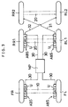
- Fig. 3 shows an embodiment in which the ABS control system of the invention is applied to a trailer of the front 1-axle/2-wheel, rear two-axle/4-wheel diagonal two-wheel simultaneous control type.
- the independently acting control unit U is provided in a total of 4 positions, namely 2 positions, right and left, for the front wheels and 2 positions, right and left, for the four rear wheels, with the rear right wheel RR2 being connected to the control unit U for the rear left wheel RL1 through a connecting pipe 31 and the rear left wheel RL2 to the control unit U for the rear right wheel RR1 through a connecting pipe 32, and the actuators A of these four control units U are respectively supplied with a brake fluid from the master cylinder MP.
- the trailer is, thus, equipped with independently acting antilock brake systems ABC in two positions, right and left, for the front wheels and two positions, right and left, for the four rear wheels, with the respective actuators A of said control units receiving drive commands from the corresponding controllers C according to detected stress values, such as road surface friction force or road surface friction coefficient values, for each front wheel and for each couple of rear wheels couples being driven to adjust the brake fluid pressures acting on the respective wheels independently so that antilock brakes can be applied for sudden stopping without regard to chassis length or axle-to-axle distance for each front wheel and for each couple of rear wheels independently.
- detected stress values such as road surface friction force or road surface friction coefficient values
- the actuator A of each control unit is supplied with a brake fluid from the master cylinder MP through a brake fluid line 30 and, therefore, complexity is introduced by the routing of the fluid line 30.
- a control hydraulic pressure source S comprising a high-pressure control hydraulic pressure generating means, a fluid reservoir means and a reversing means is disposed for each control unit U as shown in Fig. 4
- the brake fluid line can be dispensed with and an antilock brake system having its own control hydraulic pressure source can be independently provided for each wheel or each set of wheels.
- a foot brake master cylinder MP is additionally provided as indicated by broken lines in Fig. 4 so as to make up for deficiencies in brake fluid pressure in the control hydraulic pressure sources S, the actuators of the respective control units can be driven at exact fluid pressures for precision control.
- the letter G represents a signal transmission system and l represents its signal line.
Landscapes
- Engineering & Computer Science (AREA)
- Transportation (AREA)
- Mechanical Engineering (AREA)
- Physics & Mathematics (AREA)
- Fluid Mechanics (AREA)
- Electromagnetism (AREA)
- Microelectronics & Electronic Packaging (AREA)
- Regulating Braking Force (AREA)
Applications Claiming Priority (3)
| Application Number | Priority Date | Filing Date | Title |
|---|---|---|---|
| JP272241/92 | 1992-08-27 | ||
| JP27224192A JP3366915B2 (ja) | 1992-08-27 | 1992-08-27 | 車両のアンチロックブレーキ装置の制御システム |
| JP27224192 | 1992-08-27 |
Publications (3)
| Publication Number | Publication Date |
|---|---|
| EP0584829A2 true EP0584829A2 (de) | 1994-03-02 |
| EP0584829A3 EP0584829A3 (en) | 1995-08-30 |
| EP0584829B1 EP0584829B1 (de) | 2002-05-08 |
Family
ID=17511100
Family Applications (1)
| Application Number | Title | Priority Date | Filing Date |
|---|---|---|---|
| EP93113695A Expired - Lifetime EP0584829B1 (de) | 1992-08-27 | 1993-08-26 | Blockierschutz-Bremssystem für Fahrzeuge |
Country Status (4)
| Country | Link |
|---|---|
| US (3) | US20010035676A1 (de) |
| EP (1) | EP0584829B1 (de) |
| JP (1) | JP3366915B2 (de) |
| DE (1) | DE69331890T2 (de) |
Cited By (3)
| Publication number | Priority date | Publication date | Assignee | Title |
|---|---|---|---|---|
| WO2008017850A1 (en) * | 2006-08-09 | 2008-02-14 | Cambridge Enterprise Ltd. | Air braking system |
| US7490913B2 (en) * | 2003-07-22 | 2009-02-17 | Knorr-Bremse Systeme Fuer Nutzfahrzeuge Gmbh | Trailer and semi-trailer brake valve with an integrated control of the air suspension |
| EP1736387A3 (de) * | 2005-06-24 | 2009-03-25 | Dana Heavy Vehicle Systems Group, LLC | Achsstummel mit Mehrzweck-Beschleunigungsmessvorrichtung |
Families Citing this family (10)
| Publication number | Priority date | Publication date | Assignee | Title |
|---|---|---|---|---|
| JP3366915B2 (ja) * | 1992-08-27 | 2003-01-14 | 日本電子工業株式会社 | 車両のアンチロックブレーキ装置の制御システム |
| DE102004009467A1 (de) * | 2004-02-27 | 2005-09-15 | Daimlerchrysler Ag | Steuerungssystem für ein Fahrzeug |
| WO2005110831A1 (en) * | 2004-05-13 | 2005-11-24 | Haldex Brake Products Ab | Modular braking system |
| US20060119174A1 (en) * | 2004-12-06 | 2006-06-08 | Bendix Commercial Vehicle Systems Llc | Distributed antilock brake system |
| JP2007030881A (ja) * | 2006-11-13 | 2007-02-08 | Hitachi Ltd | 車両用電動ブレーキ装置 |
| DE102008003381B4 (de) * | 2008-01-07 | 2024-10-02 | Zf Cv Systems Hannover Gmbh | Bremsanlage für ein Fahrzeug |
| JP4701254B2 (ja) * | 2008-02-04 | 2011-06-15 | 日立オートモティブシステムズ株式会社 | ブレーキ装置 |
| JP5705598B2 (ja) * | 2011-03-09 | 2015-04-22 | Ntn株式会社 | モータの診断方法 |
| US10118073B2 (en) | 2016-04-04 | 2018-11-06 | Worldpro Group, LLC | Interactive apparatus and methods for muscle strengthening |
| DE112019007844T5 (de) * | 2019-10-29 | 2022-07-14 | Mitsubishi Electric Corporation | Fahrzeugantiblockierbremssystem-Steuervorrichtung |
Family Cites Families (57)
| Publication number | Priority date | Publication date | Assignee | Title |
|---|---|---|---|---|
| US3503654A (en) * | 1966-06-15 | 1970-03-31 | Rockwell Standard Co | Brake system |
| US3479074A (en) * | 1967-02-15 | 1969-11-18 | Schlage Lock Co | Lock mounting |
| GB1248787A (en) * | 1968-12-13 | 1971-10-06 | Mullard Ltd | Improvements in or relating to anti-lock brake systems |
| DE1914336A1 (de) * | 1969-03-21 | 1970-10-01 | Daimler Benz Ag | Vorrichtung zum Regeln der Bremsen eines Fahrzeuges,insbesondere zum Verhindern des Blockierens der Raeder |
| JPS4947225B1 (de) * | 1969-08-26 | 1974-12-14 | ||
| GB1319202A (en) * | 1971-03-27 | 1973-06-06 | Fiat Spa | Tractor and trailer combination |
| GB1359487A (en) * | 1971-09-24 | 1974-07-10 | Mullard Ltd | Brake antilock mechanism |
| JPS561257B2 (de) * | 1973-06-25 | 1981-01-12 | ||
| SE386860B (sv) * | 1974-03-01 | 1976-08-23 | Saab Scania Ab | Sett och bromsreglersystem for att reglera bromsforlopp for ett fordon |
| US4166657A (en) * | 1975-02-19 | 1979-09-04 | Blomberg Folke Ivar | Brake actuating and relieving structure |
| DE2614016A1 (de) * | 1976-04-01 | 1977-10-06 | Teldix Gmbh | Antiblockierregelsystem |
| DE2933336C2 (de) * | 1979-08-17 | 1986-04-03 | Wabco Westinghouse Fahrzeugbremsen GmbH, 3000 Hannover | Blockierschutzregelsystem mit Sicherheitsschaltungen |
| GB2058975A (en) * | 1979-09-15 | 1981-04-15 | Lucas Industries Ltd | Vehicle brake actuator |
| GB2074276B (en) * | 1979-09-18 | 1983-09-21 | Lucas Industries Ltd | Wheel slide protection system |
| JPS5777244A (en) * | 1980-10-30 | 1982-05-14 | Akebono Brake Ind Co Ltd | Brake control for vehicle |
| JPS5780956A (en) | 1980-11-10 | 1982-05-20 | Nippon Air Brake Co Ltd | Hydraulic control for anti-skid device |
| DE3126102A1 (de) * | 1981-07-02 | 1983-01-20 | Robert Bosch Gmbh, 7000 Stuttgart | Antiblockierregelsystem |
| GB8315346D0 (en) * | 1983-06-03 | 1983-07-06 | Trw Probe Electronics Co Ltd | Strain gauge assemblies |
| DE3345694C2 (de) * | 1983-12-17 | 1996-04-04 | Teves Gmbh Alfred | Hydraulische Bremsanlage |
| DE3419714A1 (de) * | 1984-05-26 | 1985-11-28 | Robert Bosch Gmbh, 7000 Stuttgart | Antiblockierregelsystem |
| GB8418950D0 (en) * | 1984-07-25 | 1984-08-30 | Lucas Ind Plc | Hydraulic anti-skid systems |
| JPH0637162B2 (ja) * | 1984-12-12 | 1994-05-18 | 住友電気工業株式会社 | 自動車の制動力制御装置 |
| US4685745A (en) * | 1985-01-23 | 1987-08-11 | Wabco Westinghouse Fahrzeugbremsen Gmbh | Motor vehicle brake pressure-regulating apparatus |
| DE3526559A1 (de) * | 1985-07-25 | 1987-01-29 | Wabco Westinghouse Fahrzeug | Antiblockiersystem |
| JPS6277270A (ja) | 1985-09-30 | 1987-04-09 | Fujitsu Ten Ltd | 自動車用アンチスキツド制御装置 |
| JP2590825B2 (ja) | 1986-07-12 | 1997-03-12 | トヨタ自動車株式会社 | マニユアル・電気二系統ブレーキ装置 |
| US4749238A (en) * | 1987-04-13 | 1988-06-07 | Allied Corporation | Electronically controlled fluid pressure braking system |
| USRE33697E (en) * | 1987-04-27 | 1991-09-24 | Tractor-trailer brake control system | |
| US4768840A (en) * | 1987-04-27 | 1988-09-06 | Eaton Corporation | Brake control system and method |
| JP2641240B2 (ja) * | 1988-03-30 | 1997-08-13 | 曙ブレーキ工業株式会社 | アンチロック制御用モジュレータ |
| US4863221A (en) * | 1988-08-18 | 1989-09-05 | Eaton Corporation | Tandem drive axle anti-lock brake system |
| US4828334A (en) * | 1988-09-02 | 1989-05-09 | General Motors Corporation | Antilock brake control system |
| JPH03220056A (ja) * | 1988-10-13 | 1991-09-27 | Nippon Denshi Kogyo Kk | 路面摩擦力検出装置及び路面摩擦係数検出装置並びに車両のアンチロックブレーキ装置 |
| EP0363570B1 (de) * | 1988-10-13 | 1996-02-21 | Japan Electronics Industry, Ltd. | Strassenoberflächen-Reibungsaufnehmer und Strassenoberflächen-Reibungskoeffizienten-Aufnehmer und Fahrzeug-Blockierschutz-Bremsanlage |
| DE3901776A1 (de) * | 1989-01-21 | 1990-07-26 | Wabco Westinghouse Fahrzeug | Sicherheitsschaltung |
| JP2736392B2 (ja) | 1989-12-15 | 1998-04-02 | 日本電子工業株式会社 | 車両の車輪作用力検出装置、車両のアンチロックブレーキ装置および車両のトラクションコントロール装置 |
| US5009294A (en) * | 1990-01-19 | 1991-04-23 | General Motors Corporation | Vehicle traction control system |
| JPH0781923B2 (ja) | 1990-01-20 | 1995-09-06 | 日本電子工業株式会社 | スピンドルによる路面摩擦力検出装置、垂直荷重検出装置及び路面摩擦係数検出装置 |
| US5186042A (en) * | 1990-03-19 | 1993-02-16 | Japan Electronics Industry, Ltd. | Device for measuring action force of wheel and device for measuring stress of structure |
| JP2736395B2 (ja) * | 1990-03-19 | 1998-04-02 | 日本電子工業 株式会社 | 車輪作用力測定装置及び構造体の応力測定装置 |
| US6032520A (en) * | 1990-03-19 | 2000-03-07 | Japan Electronics Industry, Limited | Device for measuring action force of wheel and device for measuring stress of structure |
| DE4022671A1 (de) * | 1990-07-17 | 1992-01-23 | Wabco Westinghouse Fahrzeug | Elektronisches bremssystem fuer stassenfahrzeuge |
| US5090779A (en) * | 1990-08-27 | 1992-02-25 | Rockwell International Corporation | Acoustic signal transmission between a tractor and trailer within the air brake system |
| DE4100966A1 (de) * | 1991-01-15 | 1992-07-16 | Teves Gmbh Alfred | Radbremsbaugruppe fuer modulares bremssystem |
| DE4114861A1 (de) * | 1991-05-07 | 1992-11-12 | Wabco Westinghouse Fahrzeug | Fahrzeug mit liftbarer nachlaufachse |
| US5258912A (en) * | 1991-06-24 | 1993-11-02 | General Motors Corporation | Wheel understeer speed control |
| US5288139A (en) * | 1992-06-05 | 1994-02-22 | Allied-Signal Inc. | Electropneumatic braking system |
| DE4227083C2 (de) * | 1992-08-17 | 2002-06-27 | Knorr Bremse Systeme | Elektronisches Bremssystem, insbesondere für Straßenfahrzeuge |
| JP3366915B2 (ja) * | 1992-08-27 | 2003-01-14 | 日本電子工業株式会社 | 車両のアンチロックブレーキ装置の制御システム |
| DE4241844A1 (de) * | 1992-12-11 | 1994-06-16 | Bosch Gmbh Robert | Bremssystem |
| US5303986A (en) * | 1993-02-01 | 1994-04-19 | Allied-Signal Inc. | Electropneumatic brake control with retarder apportioning |
| JP2791452B2 (ja) * | 1993-02-15 | 1998-08-27 | 日本電子工業株式会社 | 車輪作用力測定装置 |
| US6006597A (en) * | 1993-02-15 | 1999-12-28 | Japan Electronics Industry, Limited | Wheel-acting force measuring device |
| JP3131642B2 (ja) * | 1994-09-14 | 2001-02-05 | 日本電子工業株式会社 | 応力複合化センサ及びこれを用いた構造体の応力測定装置 |
| US5569857A (en) * | 1994-11-29 | 1996-10-29 | Japan Electronics Industry, Limited | Vehicle stress detecting and measuring method and stress detecting device using said method |
| JPH092240A (ja) * | 1995-06-14 | 1997-01-07 | Nippon Denshi Kogyo Kk | Abs装置に於けるブレーキ減圧制御点検出法 |
| EP0788955B1 (de) * | 1995-09-19 | 2003-11-26 | Japan Electronics Industry, Ltd. | Steuerverfahren für Antiblockier-Bremssysteme |
-
1992
- 1992-08-27 JP JP27224192A patent/JP3366915B2/ja not_active Expired - Fee Related
-
1993
- 1993-08-26 DE DE69331890T patent/DE69331890T2/de not_active Expired - Lifetime
- 1993-08-26 EP EP93113695A patent/EP0584829B1/de not_active Expired - Lifetime
-
2001
- 2001-03-19 US US09/812,264 patent/US20010035676A1/en not_active Abandoned
-
2002
- 2002-08-07 US US10/213,565 patent/US7052096B2/en not_active Expired - Fee Related
-
2006
- 2006-05-18 US US11/436,777 patent/US20060220454A1/en not_active Abandoned
Cited By (4)
| Publication number | Priority date | Publication date | Assignee | Title |
|---|---|---|---|---|
| US7490913B2 (en) * | 2003-07-22 | 2009-02-17 | Knorr-Bremse Systeme Fuer Nutzfahrzeuge Gmbh | Trailer and semi-trailer brake valve with an integrated control of the air suspension |
| EP1736387A3 (de) * | 2005-06-24 | 2009-03-25 | Dana Heavy Vehicle Systems Group, LLC | Achsstummel mit Mehrzweck-Beschleunigungsmessvorrichtung |
| WO2008017850A1 (en) * | 2006-08-09 | 2008-02-14 | Cambridge Enterprise Ltd. | Air braking system |
| US9610929B2 (en) | 2006-08-09 | 2017-04-04 | Haldex Brake Products Ltd. | Air braking system |
Also Published As
| Publication number | Publication date |
|---|---|
| DE69331890T2 (de) | 2003-02-06 |
| US7052096B2 (en) | 2006-05-30 |
| US20060220454A1 (en) | 2006-10-05 |
| EP0584829B1 (de) | 2002-05-08 |
| EP0584829A3 (en) | 1995-08-30 |
| JPH0672310A (ja) | 1994-03-15 |
| DE69331890D1 (de) | 2002-06-13 |
| JP3366915B2 (ja) | 2003-01-14 |
| US20020195874A1 (en) | 2002-12-26 |
| US20010035676A1 (en) | 2001-11-01 |
Similar Documents
| Publication | Publication Date | Title |
|---|---|---|
| US5462342A (en) | Electronic brake system for separately controlling nondriven front wheels and driven rear wheels | |
| US7114787B2 (en) | Braking system for trailers of utility vehicles | |
| EP0584829A2 (de) | Blockierschutz-Bremssystem für Fahrzeuge | |
| US5211449A (en) | Vehicle with liftable following axle | |
| US4818035A (en) | Tractor-trailer brake control system | |
| US4984852A (en) | Trailer mounted tractor-trailer brake control system | |
| US4740041A (en) | Anti-locking brake control system for motor vehicles | |
| US6505893B2 (en) | Vehicle brake system having two brake circuits | |
| US5105903A (en) | Brake system with anti-lock control for all-wheel driven automotive vehicles | |
| US6749271B1 (en) | Brake system for vehicles, especially commercial vehicles | |
| US3832012A (en) | Antiskid braking circuit | |
| US4863221A (en) | Tandem drive axle anti-lock brake system | |
| US5456526A (en) | ABS control for individual axles of a three axle vehicle | |
| US4688858A (en) | Slip-controlled brake system for motor vehicles | |
| USRE33697E (en) | Tractor-trailer brake control system | |
| US5172959A (en) | Anti-lock braking system for all-wheel drive vehicles | |
| US20240059264A1 (en) | Method for operating a control system of a vehicle with a steering brake function and traction control system | |
| EP3789255B1 (de) | Bremsensystem für ein nutzfahrzeug | |
| US6672683B1 (en) | Electronically regulated brake system | |
| JPH07102802B2 (ja) | トラクションスリップ制御付きブレーキシステム | |
| JPS59114149A (ja) | アンチスキツド装置 | |
| JPH0338415B2 (de) | ||
| JPH05170078A (ja) | 多軸車両におけるアンチスキッドブレーキ制御システム | |
| JPS61196852A (ja) | 制動力制御装置 | |
| EP1509433A1 (de) | Antiblockierbremsen für ein fahrzeug mit lenkbaren rädern |
Legal Events
| Date | Code | Title | Description |
|---|---|---|---|
| PUAI | Public reference made under article 153(3) epc to a published international application that has entered the european phase |
Free format text: ORIGINAL CODE: 0009012 |
|
| AK | Designated contracting states |
Kind code of ref document: A2 Designated state(s): DE FR GB IT SE |
|
| PUAL | Search report despatched |
Free format text: ORIGINAL CODE: 0009013 |
|
| AK | Designated contracting states |
Kind code of ref document: A3 Designated state(s): DE FR GB IT SE |
|
| 17P | Request for examination filed |
Effective date: 19960216 |
|
| 17Q | First examination report despatched |
Effective date: 19960419 |
|
| GRAG | Despatch of communication of intention to grant |
Free format text: ORIGINAL CODE: EPIDOS AGRA |
|
| GRAG | Despatch of communication of intention to grant |
Free format text: ORIGINAL CODE: EPIDOS AGRA |
|
| GRAG | Despatch of communication of intention to grant |
Free format text: ORIGINAL CODE: EPIDOS AGRA |
|
| GRAH | Despatch of communication of intention to grant a patent |
Free format text: ORIGINAL CODE: EPIDOS IGRA |
|
| REG | Reference to a national code |
Ref country code: GB Ref legal event code: IF02 |
|
| GRAH | Despatch of communication of intention to grant a patent |
Free format text: ORIGINAL CODE: EPIDOS IGRA |
|
| GRAA | (expected) grant |
Free format text: ORIGINAL CODE: 0009210 |
|
| AK | Designated contracting states |
Kind code of ref document: B1 Designated state(s): DE FR GB IT SE |
|
| REF | Corresponds to: |
Ref document number: 69331890 Country of ref document: DE Date of ref document: 20020613 |
|
| ET | Fr: translation filed | ||
| PLBE | No opposition filed within time limit |
Free format text: ORIGINAL CODE: 0009261 |
|
| 26N | No opposition filed |
Effective date: 20030211 |
|
| REG | Reference to a national code |
Ref country code: FR Ref legal event code: ST Effective date: 20070430 |
|
| REG | Reference to a national code |
Ref country code: FR Ref legal event code: D3 |
|
| PGFP | Annual fee paid to national office [announced via postgrant information from national office to epo] |
Ref country code: IT Payment date: 20070830 Year of fee payment: 15 |
|
| PG25 | Lapsed in a contracting state [announced via postgrant information from national office to epo] |
Ref country code: FR Free format text: LAPSE BECAUSE OF NON-PAYMENT OF DUE FEES Effective date: 20060831 |
|
| PGFP | Annual fee paid to national office [announced via postgrant information from national office to epo] |
Ref country code: FR Payment date: 20081212 Year of fee payment: 16 |
|
| REG | Reference to a national code |
Ref country code: GB Ref legal event code: 732E Free format text: REGISTERED BETWEEN 20090430 AND 20090506 |
|
| PGFP | Annual fee paid to national office [announced via postgrant information from national office to epo] |
Ref country code: GB Payment date: 20081210 Year of fee payment: 16 |
|
| PG25 | Lapsed in a contracting state [announced via postgrant information from national office to epo] |
Ref country code: IT Free format text: LAPSE BECAUSE OF NON-PAYMENT OF DUE FEES Effective date: 20080826 |
|
| PGFP | Annual fee paid to national office [announced via postgrant information from national office to epo] |
Ref country code: SE Payment date: 20081230 Year of fee payment: 16 |
|
| REG | Reference to a national code |
Ref country code: FR Ref legal event code: TP |
|
| PGFP | Annual fee paid to national office [announced via postgrant information from national office to epo] |
Ref country code: DE Payment date: 20090821 Year of fee payment: 17 |
|
| GBPC | Gb: european patent ceased through non-payment of renewal fee |
Effective date: 20090826 |
|
| REG | Reference to a national code |
Ref country code: FR Ref legal event code: ST Effective date: 20100430 |
|
| PG25 | Lapsed in a contracting state [announced via postgrant information from national office to epo] |
Ref country code: GB Free format text: LAPSE BECAUSE OF NON-PAYMENT OF DUE FEES Effective date: 20090826 |
|
| PG25 | Lapsed in a contracting state [announced via postgrant information from national office to epo] |
Ref country code: SE Free format text: LAPSE BECAUSE OF NON-PAYMENT OF DUE FEES Effective date: 20090827 |
|
| REG | Reference to a national code |
Ref country code: DE Ref legal event code: R119 Ref document number: 69331890 Country of ref document: DE Effective date: 20110301 |
|
| PG25 | Lapsed in a contracting state [announced via postgrant information from national office to epo] |
Ref country code: DE Free format text: LAPSE BECAUSE OF NON-PAYMENT OF DUE FEES Effective date: 20110301 |
|
| PG25 | Lapsed in a contracting state [announced via postgrant information from national office to epo] |
Ref country code: FR Free format text: LAPSE BECAUSE OF NON-PAYMENT OF DUE FEES Effective date: 20090831 |