EP0585010A2 - Scheibenwischersystem - Google Patents
Scheibenwischersystem Download PDFInfo
- Publication number
- EP0585010A2 EP0585010A2 EP93306384A EP93306384A EP0585010A2 EP 0585010 A2 EP0585010 A2 EP 0585010A2 EP 93306384 A EP93306384 A EP 93306384A EP 93306384 A EP93306384 A EP 93306384A EP 0585010 A2 EP0585010 A2 EP 0585010A2
- Authority
- EP
- European Patent Office
- Prior art keywords
- wiper
- pivot lever
- actuator
- eccentric cam
- lever
- Prior art date
- Legal status (The legal status is an assumption and is not a legal conclusion. Google has not performed a legal analysis and makes no representation as to the accuracy of the status listed.)
- Granted
Links
Images


Classifications
-
- B—PERFORMING OPERATIONS; TRANSPORTING
- B60—VEHICLES IN GENERAL
- B60S—SERVICING, CLEANING, REPAIRING, SUPPORTING, LIFTING, OR MANOEUVRING OF VEHICLES, NOT OTHERWISE PROVIDED FOR
- B60S1/00—Cleaning of vehicles
- B60S1/02—Cleaning windscreens, windows or optical devices
- B60S1/04—Wipers or the like, e.g. scrapers
- B60S1/06—Wipers or the like, e.g. scrapers characterised by the drive
- B60S1/16—Means for transmitting drive
- B60S1/18—Means for transmitting drive mechanically
- B60S1/185—Means for transmitting drive mechanically with means for stopping or setting the wipers at their limit of movement
-
- B—PERFORMING OPERATIONS; TRANSPORTING
- B60—VEHICLES IN GENERAL
- B60S—SERVICING, CLEANING, REPAIRING, SUPPORTING, LIFTING, OR MANOEUVRING OF VEHICLES, NOT OTHERWISE PROVIDED FOR
- B60S1/00—Cleaning of vehicles
- B60S1/02—Cleaning windscreens, windows or optical devices
- B60S1/04—Wipers or the like, e.g. scrapers
- B60S1/06—Wipers or the like, e.g. scrapers characterised by the drive
- B60S1/16—Means for transmitting drive
- B60S1/18—Means for transmitting drive mechanically
- B60S1/24—Means for transmitting drive mechanically by rotary cranks
- B60S1/245—Means for transmitting drive mechanically by rotary cranks with particular rod arrangements between the motor driven axle and the wiper arm axle
-
- Y—GENERAL TAGGING OF NEW TECHNOLOGICAL DEVELOPMENTS; GENERAL TAGGING OF CROSS-SECTIONAL TECHNOLOGIES SPANNING OVER SEVERAL SECTIONS OF THE IPC; TECHNICAL SUBJECTS COVERED BY FORMER USPC CROSS-REFERENCE ART COLLECTIONS [XRACs] AND DIGESTS
- Y10—TECHNICAL SUBJECTS COVERED BY FORMER USPC
- Y10S—TECHNICAL SUBJECTS COVERED BY FORMER USPC CROSS-REFERENCE ART COLLECTIONS [XRACs] AND DIGESTS
- Y10S318/00—Electricity: motive power systems
- Y10S318/02—Windshield wiper controls
-
- Y—GENERAL TAGGING OF NEW TECHNOLOGICAL DEVELOPMENTS; GENERAL TAGGING OF CROSS-SECTIONAL TECHNOLOGIES SPANNING OVER SEVERAL SECTIONS OF THE IPC; TECHNICAL SUBJECTS COVERED BY FORMER USPC CROSS-REFERENCE ART COLLECTIONS [XRACs] AND DIGESTS
- Y10—TECHNICAL SUBJECTS COVERED BY FORMER USPC
- Y10T—TECHNICAL SUBJECTS COVERED BY FORMER US CLASSIFICATION
- Y10T74/00—Machine element or mechanism
- Y10T74/16—Alternating-motion driven device with means during operation to adjust stroke
- Y10T74/1625—Stroke adjustable to zero and/or reversible in phasing
- Y10T74/1658—Eccentric and strap drive, shiftable eccentric
- Y10T74/1667—Changing the extent of eccentricity
-
- Y—GENERAL TAGGING OF NEW TECHNOLOGICAL DEVELOPMENTS; GENERAL TAGGING OF CROSS-SECTIONAL TECHNOLOGIES SPANNING OVER SEVERAL SECTIONS OF THE IPC; TECHNICAL SUBJECTS COVERED BY FORMER USPC CROSS-REFERENCE ART COLLECTIONS [XRACs] AND DIGESTS
- Y10—TECHNICAL SUBJECTS COVERED BY FORMER USPC
- Y10T—TECHNICAL SUBJECTS COVERED BY FORMER US CLASSIFICATION
- Y10T74/00—Machine element or mechanism
- Y10T74/18—Mechanical movements
- Y10T74/18056—Rotary to or from reciprocating or oscillating
- Y10T74/18184—Crank, pitman, and lever
- Y10T74/182—Multiple levers
-
- Y—GENERAL TAGGING OF NEW TECHNOLOGICAL DEVELOPMENTS; GENERAL TAGGING OF CROSS-SECTIONAL TECHNOLOGIES SPANNING OVER SEVERAL SECTIONS OF THE IPC; TECHNICAL SUBJECTS COVERED BY FORMER USPC CROSS-REFERENCE ART COLLECTIONS [XRACs] AND DIGESTS
- Y10—TECHNICAL SUBJECTS COVERED BY FORMER USPC
- Y10T—TECHNICAL SUBJECTS COVERED BY FORMER US CLASSIFICATION
- Y10T74/00—Machine element or mechanism
- Y10T74/20—Control lever and linkage systems
- Y10T74/20576—Elements
- Y10T74/20582—Levers
- Y10T74/206—Adjustable
-
- Y—GENERAL TAGGING OF NEW TECHNOLOGICAL DEVELOPMENTS; GENERAL TAGGING OF CROSS-SECTIONAL TECHNOLOGIES SPANNING OVER SEVERAL SECTIONS OF THE IPC; TECHNICAL SUBJECTS COVERED BY FORMER USPC CROSS-REFERENCE ART COLLECTIONS [XRACs] AND DIGESTS
- Y10—TECHNICAL SUBJECTS COVERED BY FORMER USPC
- Y10T—TECHNICAL SUBJECTS COVERED BY FORMER US CLASSIFICATION
- Y10T74/00—Machine element or mechanism
- Y10T74/21—Elements
- Y10T74/2173—Cranks and wrist pins
- Y10T74/2179—Adjustable
Definitions
- the present invention relates to a wiper system, and in particular to a wiper system which can variably control its wiping angle.
- Some of the conventional wiper systems for vehicles such as automobiles can change the speed of the movement of the wiper depending on the intensity of rain fall. If the rain fall is substantial, the wiping speed is increased, and vice versa.
- Some wiper systems are provided with the intermittent operation mode in which the wiper system is activated in an intermittent manner. This mode is useful when there is minimal rain fall.
- the speed of the wiper movement can be reduced in low speed range and increased in high speed range so that the optimum control of the wiper can be achieved in accordance with the vehicle speed.
- the varying of the wiping angle may be required to take place during the wiping movement. Therefore, the motor which, for instance, consists of an electric motor is required to be powerful enough to change the wiping angle without being hindered by the force acting upon the wiper arm for the purpose of driving the wiper arm into the wiping movement by overcoming the frictional force which the wiper arm experiences. As a result, the wiper system tends to be bulky, and create problems in designing its mounting arrangement.
- a primary object of the present invention is to provide a wiper system equipped with means for changing the wiping angle which is compact in size.
- a second object of the present invention is to provide a wiper system equipped with means for completing the process of changing the wiping angle without requiring an excessively bulky drive structure.
- a wiper system comprising: wiper motor means; a wiper arm having a base end pivotally supported by a vehicle body and a free end carrying a wiper blade; linkage means for transmitting movement of an output end of the wiper motor means to the wiper arm so as to achieve a desired wiping movement of the wiper blade; and a wiping angle varying assembly included within the linkage means for varying the range of angle of the wiping movement of the wiper blade; the wiping angle varying assembly comprising actuator means, eccentric cam means provided in a path of transmitting the movement of the output end of the motor to the wiper arm, and control means for activating the actuator means so as to move the eccentric cam means and thereby change the range of angle of the wiping movement by altering a configuration of the linkage means; the control means activating the actuator means only when a first force transmitted through the linkage means from the wiper motor means to the wiper arm does not substantially oppose a second force produced by the actuator means to
- control means activates the actuator means with such a timing that the first force transmitted through the linkage means from the wiper motor means to the wiper arm tends to assist the second force produced by the actuator means to move the eccentric cam means.
- the actuator means is not required to overcome the first force produced by the wiper motor means to achieve a desired change in the configuration of the linkage means.
- the actuator means may consist of a relatively small motor, and can quickly achieve the desired change in the configuration of the linkage means.
- a pair of wiper arms each pivotally supported by the vehicle body at a base end thereof and carrying a wiper blade at a free end thereof; and the linkage means comprises; a first pivot lever pivotally supported by the vehicle body, the base end of a first one of the wiper arm being integrally connected to the second pivot lever; a second pivot lever pivotally supported by the vehicle body, the base end of a second one of the wiper arm being integrally connected to the second pivot lever; a first connecting rod having a first end connected to an output end of the wiper motor means and a second end pivotally connected to a free end of the first pivot lever via joint means; and a second connecting rod having a firstend connected to a free end of the first pivot lever and a second end pivotally connected to a free end of the second pivot lever; the joint means being adapted to be moved toward and away from a center of rotation of the first pivot lever by the actuator means and the eccentric cam means.
- eccentric cam means used herein should be understood in its broadest meaning, and includes not only eccentric cams but also all other mechanical or other means which act between two members of the linkage means and are subjected to the force transmitted from the wiper motor means to the wiper arms when achieving the required change in the linkage means.
- the eccentric cam means and the joint means comprise a lever arm member pivotally secured to the first pivot lever, and a ball joint member secured to the lever arm member offset from a center of rotation of the lever arm member relative to the first pivot lever, the second end of the first connecting rod being coupled to the ball joint member.
- the first pivot lever is pivotally supported by the vehicle body via a hollow pivot shaft integrally attached to the first pivot lever
- the actuator means comprises an electric actuator motor coaxially received in the pivot shaft, an actuator arm member integrally secured to an output shaft of the actuator motor, and a link member having a first end pivotally connected to the actuator arm member and a second end pivotally connected to a part of the lever arm member spaced from a center of rotation of the lever arm member relative to the first pivot lever.
- the actuator means can be conveniently incorporated in linkage means which is very similar to the conventional linkage for normal wiper systems.
- control means comprises a position sensor for detecting positions of the first pivot lever immediately before and after a reversal point at which the first pivot lever changes its direction of movement, and selectively activates the actuator means when the first pivot lever is immediately before or after the reversal point depending on a relationship between directions of the first and second forces.
- Figure 1 is a schematic view showing the variable range of the sweeping angle of the wiper system according to the present invention.
- Figure 1 only shows the range of the sweeping angle for the driver's side, but the same thing applies to the passenger's side.
- the wiper arm 1 for the driver's side is actuated by a wiper motor 2 via a linkage mechanism so as to synchronize with the wiper arm for the passenger's side which is not shown in the drawing.
- a first pivot lever 5 is made to undergo an angular movement via a first connecting rod 4a
- a second pivot lever 6 is likewise made to undergo a similar angular movement via a second connecting rod 4b which is connected between the first pivot lever 5 and the second pivot lever 6.
- the wiper arms for the driver's side and the passenger's side integrally connected to the corresponding pivot levers 5 and 6 are thereby made to undergo the desired sweeping movement relative to a front windshield 7.
- the sweeping range for the intermittent mode is the sector area I-I indicated by the solid lines
- the sweeping range for the low speed mode is the sector area L-L indicated by the broken lines
- the sweeping range for the high speed mode is the sector area H-H indicated by the one-dot chain lines, the sweeping range thus being progressively narrowed as the operating speed is increased.
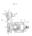
- the pivot lever 5 is rotatably supported by the vehicle body by way of a tubular pivot shaft 8 laterally and integrally extending from a base end of the pivot lever 5 and supported by the vehicle body via bearings 9.
- the pivot shaft 8 is coaxially provided with a wiper mounting shaft 8a on which an arm head of the wiper arm 11 for the passenger's side is mounted via a tapered serration coupling.
- the pivot shaft 8 accommodates therein a wiping angle varying motor 12.
- the output torque of the wiping angle varying motor 12 is taken out via a speed reduction unit 13, and the pivot lever 5 is provided with a sector-shaped relay plate 14 which surrounds an intermediate part of an output shaft 13a of the speed reduction unit 13.
- a disk-shaped crank member 15 is fixedly secured to a free end of the output shaft 13a of the speed reduction unit 13.
- a lever arm member 16 serving as an eccentric cam is pivotally attached to a free end of the pivot lever 5, and this lever arm member 16 is linked with the crank member 15 via a substantially L-shaped link rod 17.
- Ajoint ball 18a forthe first connecting rod 4a connected to the output end of the wiper motor 2 is provided in a part of the lever arm member 16 which is offset by a prescribed amount (indicated by r in the drawing) from the center of rotation of the lever arm member 16.
- the output shaft 13a of the reduction unit 13 rotates over a prescribed angle in either direction, and the resulting angular movement of the lever arm member 16 causes the joint ball 18a to move along a circular path of a radius r centered around the center of rotation of the lever arm member 16.
- Figures 2 and 3 show the case in which the wiper system is operating in the high speed mode, and the effective radius of rotation of the pivot lever 5 in this case is Rh as shown in Figure 3.
- the link rod 17 and the lever arm member 16 are made to rotate in such a manner that the terminal point of the movement of the connecting point between the crank member 15 and the link rod 17 and that of the connecting point between the lever arm member 16 and the link rod 17 are indicated by H in the drawing in the case of the high speed mode, by L in the case of the low speed mode, and by I in the case of the OFF position and the intermittent mode.
- the side of the pivot lever 15, opposite to the side to which the joint ball 18a is connected, has a joint ball 18b of the second connecting rod 4b connected thereto.
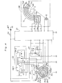
- FIG. 4 shows a circuit diagram of the control circuitry of the wiper system of the present invention, and its details are described in the following.
- a control unit 21 including a CPU and power transistors for effecting the control of the wiper system obtains its electric power from a battery BT via an ignition switch IG.
- the control circuit of the wiper system comprises, in addition to the control unit 21, a wiper switch 22 for selecting the operating mode of the wiper system, an intermittent relay 23 for achieving an intermittent operation, a wiper motor unit 25 consisting of the aforementioned wiper motor 22 and a position sensor 24 operating in association with the movement of the wiper motor 22, and a wiping angle varying unit 26 consisting of the aforementioned wiping angle varying motor 12 and the relay plate 14.
- the wiper switch 22 comprises a switch unit SW1 having a pairof four-position selection contacts for selecting the OFF, intermittent, low speed and high speed operation modes, and a switch unit SW2 having a pair of two-position selection contacts for selecting the mist operation mode in which washer fluid is sprayed onto the windshield.
- the common terminal of one of the selection switches of the switch unit SW1 is connected to the normally closed terminal of one of the selection switches of the switch unit SW2, and the common terminal of the last mentioned selection switch and the normally closed terminal of the other selection switch of the switch unit SW2 are connected to the low speed drive terminal LO of the wiper motor 2.
- the B terminal or the power terminal of the wiper motor 2 is connected to the secondary end of the ignition switch IG.
- the common terminal of the other switch of the switch unit SW1 is connected to the common terminal of the other selection switch of the switch unit SW2, and the node between them is connected to the high speed drive terminal HI of the wiper motor 2.
- the selection contacts for the OFF and intermittent operation modes of the said one of the selection switch of the switch unit SW1 are connected to the common terminal of the switch RS of the intermittent relay 23.
- the normally open contact of the switch RS is grounded while the normally closed contact of the switch RS is connected to the corresponding terminal of the control unit 21.
- the low speed selection contact of the said one of the selection switches of the switch unit SW1, the high speed selection contact of the other selection switch of the switch unit SW1, and the mist selection contact of one of the selection switch of the switch unit SW2 are grounded.
- the open terminals of the switch unit SW1 and SW2 shown in Figure 4 are connected to the control unit 21 so that the control unit 21 may detect when any one of these contacts is selected although it is not shown in the drawing to avoid crowding the drawing.
- One end of the coil RL of the intermittent relay 23 is connected to the secondary end of the ignition switch IG, and the other end of the coil RL is connected to the corresponding terminal of the control unit 21.
- the position sensor 24 of the wiper motor unit 25 comprises a rotary slider assembly 24a which integrally rotates with the motor shaft of the wiper motor 2, and fixed contacts 24b through 24g coaxially arranged along four concentric circles either in annular or arcuate configuration for detecting the prescribed positions of the wiper arm.
- the rotary slider assembly 24a is provided with four sliders which slide over the innermost annular fixed contact 24b, the large and small arcuate fixed contacts 24c and 24d surrounding the annular contact 24b, the outer annular fixed contact 24e surrounding the arcuate contacts 24c and 24d, and a pair of outermost arcuate fixed contacts 24f and 24g so that a desired state of conduction can be achieved between the fixed contacts 24b through 24g according to the way they are arranged.
- the innermost contact 24b is connected to the node between the normally closed contact of the switch RS of the intermittent relay 23 and the connecting terminal of the control unit 21 corresponding thereto.
- the larger arcuate contact 24c immediately outside this contact is grounded while the smaller arcuate contact 24d corresponds to the point of reversal from the normal direction or positions for retracting the wiper arm and effecting the autostop, and is connected to the terminal B for power supply to the wiper motor 2.
- the contact 24e surrounding them is used as a common terminal, and is connected to a corresponding terminal of the control unit 21.
- the outermost contacts 24f and 24g extend on either side of a point of reversal from the reverse direction each over a certain range, and are connected to respective terminals of the control unit 21.
- the two terminals of the wiping angle varying motor 12 are connected to a corresponding pair of drive output terminals of the control unit 21.
- a moveable contact assembly 14a is fixedly secured to the motor shaft of the wiping angle varying motor 12, and has three sliders which are adapted to contact the fixed contacts 14b through 14e of the relay plate 14 as the motor rotates.
- the contacts 14b through 14e are arranged in such a pattern that the OFF, intermittent, low speed and high speed operation modes can be selectively detected as the moveable contact assembly 14a moves.
- the control unit 21 When the switch unit SW1 is switched over from the OFF position illustrated in Figure 4 to the intermittent position, the control unit 21 then detects the state of this switch unit and supplies an energization signal to the coil RL of the intermittent relay 23, and the switch RS thereof is grounded. At the same time, the low speed terminal LO of the wiper motor 2 is grounded via the switch units SW1 and SW2, and the wiper motor 2 is rotated at low speed. The control unit 21 then produces a signal which rotates the wiping angle varying motor 12 so as to place the moveable contact unit 14a at the OFF/intermittent position which is indicated by the solid lines in Figure 4.
- the joint ball 18a is positioned as illustrated in Figure 5, and its radius of rotation is Ri, as indicated in the drawing, which is smaller than Rh shown in Figure 3.
- the wiping angle is enlarged for a given stroke of the connecting rod, and the wiping action covering the relatively large range I-I is accomplished as illustrated in Figure 1.
- the intermittent relay 23 is turned on and off at an interval determined by an intermittent time setting unit not shown in the drawing, and the intermittent wiping action of the wiper arm is carried out.
- the wiping angle varying motor 12 is activated by the control unit 21 until it is detected that the moveable contact assembly 14a has moved to the low speed position according to the signal detected thereby.
- the joint ball 18a is positioned as illustrated in Figure 6, and its radius of rotation is R1 as illustrated in Figure 6 which is intermediate between the radius Rh of Figure 3 and the radius Ri of Figure 5.
- the wiping action of the wiper arm is made over the range L-L illustrated in Figure 1 which is narrower than the range for the intermittent mode but wider than the range for the high speed mode.
- the wiping angle varying motor 12 is activated by the control unit 21 until it is detected that the moveable contact unit 14a has moved to the high speed position in the same way as described above.
- the radius of rotation Rh of the joint ball 18a is maximized ( Figure 3), and the wiping action of the wiper arm is made over the narrowest range H-H indicated in Figure 1.
- the timing of actuating the wiping angle varying motor 12 is selected so as to coincide with either immediately before or immediately after the point of reversal from the reverse movement.
- These points can be detected by using the aforementioned fixed contact pair 24f and 24g. More specifically, the point immediately before the point of reversal from the reverse movement is detected as the time when the moveable contact assembly 24a which rotates in clockwise direction as indicated by the arrow A in Figure 4 is in contact with one of the fixed contacts 24f, and the point immediately afterthe point of reversal is detected as the time when the moveable contact assembly 24a is in contact with the other fixed contact 24g.
- the wiping angle varying motor 12 when the wiping angle varying motor 12 is actuated as a result of a switch over from the intermittent mode to either the high speed or the low speed mode, the direction of rotation of the lever arm member 16 caused by the wiping angle varying motor 12 is as indicated by the arrow C. Therefore, the moment M1 can be used for rotating the lever arm member 16 in the direction of the arrow C, and the small output torque of the wiping angle varying motor 12 is therefore sufficient for rotating the lever arm member 16. As a result, the wiping angle varying motor 12 can be made compact enough, for instance, to be incorporated in the pivot shaft 8, and the freedom of layout design can be expanded.
- Figure 8 is a view similar to Figure 7 showing the case in which the operation mode is switched over from the low speed mode to the high speed mode.
- the direction of rotation of the lever arm member 16 caused by the wiping angle varying motor 12 is in the direction of the arrow C in the same way as in the previous instance, but the connecting point between the lever arm member 16 and the link rod 17 is located on the other side of the center of the joint ball 18a with respect to the center of rotation of the lever arm member 16. Therefore, the leftward pushing force F2 which tends to rotate the pivot lever 5 in the direction indicated by the arrow D in Figure 8 acts upon the lever arm member 16 in such a direction as to rotate the lever arm member 16 in the direction indicated by the arrow C. Therefore, in this case also, the moment M2 arising from the pushing force F2 is conveniently used for rotating the lever arm member in the direction indicated by the arrow C.
- Figure 9 shows the case in which the operation mode is switched over from the low speed mode to the intermittent mode.
- the lever arm member 16 is rotated by the wiping angle varying motor 12 in the direction indicated by the arrow E which is opposite to the cases shown in Figures 7 and 8, the moment M3 arising from the pulling force F1 transmitted from the first connecting rod 4a immediately after the point of reversal from the reverse movement is again conveniently used for the same purpose as described above.
- Figure 10 shows the case in which the operation mode is switched over from the low high speed mode to the intermittent/high speed mode.
- the lever arm member 16 is rotated in the direction indicated by the arrow E by the wiping angle varying motor 12 in the same way as shown in Figure 9, the moment M4 arising from the pulling force F1 transmitted from the first connecting rod 4a immediately after the point of reversal from the reverse movement is again conveniently used for the same purpose as described above.
- the timing of the switch over took place immediately before or after the point of reversal from the reverse movement, but the present invention is not limited by this arrangement. It is also possible to determine the angle of rotation of the pivot lever 5 and to arrange the relative positions of the lever arm member 16 and the joint ball 18a in such a manner that the switch over may take place immediately before or after the point of reversal from the normal movement, and to combine such timings.
- the direction of movement of eccentric cam means to change the wiping angle of a wiper system is made to coincide with that of the moment or the force applied by the wiper motor to the eccentric cam means, and the eccentric cam means is thereby allowed to be moved with a relatively small drive force or torque.
- the eccentric cam means can be easily actuated even when the drive force or torque available for driving the eccentric cam means is small, and a relatively small motor can be used for driving the eccentric cam means.
- the actuating motor may be made compact in size, and the freedom of layout design can be increased.
Landscapes
- Engineering & Computer Science (AREA)
- Mechanical Engineering (AREA)
- Control Of Direct Current Motors (AREA)
- Transmission Devices (AREA)
Applications Claiming Priority (2)
| Application Number | Priority Date | Filing Date | Title |
|---|---|---|---|
| JP66272/92U | 1992-08-27 | ||
| JP1992066272U JP2575572Y2 (ja) | 1992-08-27 | 1992-08-27 | ワイパ装置 |
Publications (3)
| Publication Number | Publication Date |
|---|---|
| EP0585010A2 true EP0585010A2 (de) | 1994-03-02 |
| EP0585010A3 EP0585010A3 (en) | 1994-09-07 |
| EP0585010B1 EP0585010B1 (de) | 1998-03-04 |
Family
ID=13311045
Family Applications (1)
| Application Number | Title | Priority Date | Filing Date |
|---|---|---|---|
| EP93306384A Expired - Lifetime EP0585010B1 (de) | 1992-08-27 | 1993-08-12 | Scheibenwischersystem |
Country Status (5)
| Country | Link |
|---|---|
| US (1) | US5333351A (de) |
| EP (1) | EP0585010B1 (de) |
| JP (1) | JP2575572Y2 (de) |
| CA (1) | CA2104425C (de) |
| DE (1) | DE69317179T2 (de) |
Cited By (5)
| Publication number | Priority date | Publication date | Assignee | Title |
|---|---|---|---|---|
| EP0769436A1 (de) * | 1995-10-20 | 1997-04-23 | INDUSTRIE MAGNETI MARELLI S.p.A. | Kraftfahrzeug-Scheibenwischer |
| WO2002006094A1 (de) * | 2000-07-19 | 2002-01-24 | Robert Bosch Gmbh | Wischvorrichtung für eine scheibe |
| EP1069014A3 (de) * | 1999-07-12 | 2003-05-28 | Jidosha Denki Kogyo Kabushiki Kaisha | Wischermotor |
| WO2004056622A1 (de) * | 2002-12-19 | 2004-07-08 | Valeo Systemes D'essuyage | Wischeranlage für ein fahrzeug |
| EP1777130A1 (de) * | 1999-05-25 | 2007-04-25 | Toshio Murakami | Verfahren und Vorrichtung zum Wischen |
Families Citing this family (77)
| Publication number | Priority date | Publication date | Assignee | Title |
|---|---|---|---|---|
| FR2699759B1 (fr) * | 1992-12-17 | 1995-01-20 | Valeo Systemes Dessuyage | Motoréducteur, notamment pour l'entraînement d'un dispositif d'essuie-glace, en particulier pour véhicule automobile. |
| JP2963846B2 (ja) * | 1994-06-30 | 1999-10-18 | 株式会社ミツバ | ワイパ装置の作動角調整構造 |
| US5841249A (en) * | 1995-04-28 | 1998-11-24 | Ut Automotive Dearborn, Inc. | Multi-functional apparatus employing an intermittent motion mechanism |
| US6111378A (en) * | 1995-04-28 | 2000-08-29 | Ut Automotive Dearborn, Inc. | Window wiper motor system for an automotive vehicle |
| US5949206A (en) * | 1995-04-28 | 1999-09-07 | Ut Automotive Dearborn, Inc. | Multi-functional apparatus employing an intermittent motion mechanism |
| US5920158A (en) * | 1995-04-28 | 1999-07-06 | Miller; Robin Mihekun | Multi-functional vehicle apparatus |
| US5903114A (en) * | 1995-04-28 | 1999-05-11 | Ut Automotive Dearborn, Inc. | Multi-functional apparatus employing an intermittent motion mechanism |
| US5764010A (en) * | 1995-04-28 | 1998-06-09 | United Technologies Automotive, Inc. | Control system for an automotive vehicle multi-functional apparatus |
| US5916327A (en) * | 1995-04-28 | 1999-06-29 | Ut Automotive Dearborn, Inc. | Multi-functional apparatus employing an electromagnetic device |
| US5694812A (en) * | 1995-04-28 | 1997-12-09 | United Technologies Automotive, Inc. | Multi-functional apparatus employing an electromagnetic device and an intermittent motion mechanism |
| US5979255A (en) * | 1997-04-09 | 1999-11-09 | Lear Automotive Dearborn, Inc. | Intermittent rotary motion mechanism for use in an automotive vehicle |
| US5844382A (en) * | 1997-04-09 | 1998-12-01 | Ut Automotive Dearborn, Inc | Motion transmitting apparatus for use with an automotive vehicle multi-functional apparatus |
| DE19735818C2 (de) * | 1997-08-18 | 1999-10-21 | Daimler Chrysler Ag | Befestigungsvorrichtung für eine Scheibenwischeranlage eines Kraftfahrzeuges |
| DE19741630B4 (de) * | 1997-09-20 | 2006-04-27 | Volkswagen Ag | Wischvorrichtung |
| US5969431A (en) * | 1997-10-08 | 1999-10-19 | Lear Automotive Dearborn, Inc. | Linearly actuating multi-functional apparatus for use in an automotive vehicle |
| US6075298A (en) * | 1997-10-09 | 2000-06-13 | Lear Automotive Dearborn, Inc | Rotary and linear translation actuator performing multi-functions in an automobile |
| US5907199A (en) * | 1997-10-09 | 1999-05-25 | Ut Automotive Dearborn, Inc. | Electric motor providing multi-directional output |
| US5953786A (en) * | 1997-10-09 | 1999-09-21 | Ut Automotive Dearborn, Inc. | Bypass loop wiper/washer system |
| US5979256A (en) * | 1997-10-09 | 1999-11-09 | Ut Automotive Dearborn, Inc. | Gear drive window wiper and multi-function electric motor |
| US6002323A (en) * | 1997-10-09 | 1999-12-14 | Lear Automotive Dearborn, Inc. | Audible feedback apparatus for indicating operation and position of a movable element |
| US5981907A (en) * | 1997-10-09 | 1999-11-09 | Ut Automotive Dearborn, Inc. | Rear wiper monitoring theft deterrent circuit |
| US5889341A (en) * | 1997-10-09 | 1999-03-30 | Ut Automotive Dearborn, Inc. | Multi-functional apparatus employing a linear wiper |
| US5847519A (en) * | 1997-10-09 | 1998-12-08 | Ut Automotive Dearborn, Inc. | Multi-functional apparatus for a wiper and cable drive |
| US6003193A (en) * | 1997-10-09 | 1999-12-21 | Lear Automotive Dearborn, Inc. | Multi-functional apparatus having flexible clutch |
| US5917298A (en) * | 1997-10-09 | 1999-06-29 | Ut Automotive Dearborn, Inc. | Electric motor control system with resistor network for automobile wiper assembly |
| US5929588A (en) * | 1997-10-09 | 1999-07-27 | Ut Automotive Dearborn, Inc. | Electric motor control system for automobile wiper assembly |
| US6020576A (en) * | 1997-10-09 | 2000-02-01 | Lear Automotive Dear Born, Inc. | Temperature and windshield crack detector |
| US5920949A (en) * | 1997-10-09 | 1999-07-13 | Ut Automotive Dearborn, Inc. | Rocking wiper mechanism |
| US5920159A (en) * | 1997-10-09 | 1999-07-06 | Ut Automotive Dearborn, Inc. | Multi-functional apparatus employing a flexible drive element for selectively actuating multiple output systems |
| US5977678A (en) * | 1997-10-09 | 1999-11-02 | Ut Automotive Dearborn, Inc. | Magnetic coupling mechanism for use in an automotive vehicle |
| US5986351A (en) * | 1997-10-09 | 1999-11-16 | Lear Automotive Dearborn, Inc. | Bi-directional lever for activating automotive liftgate lock mechanism |
| US5924324A (en) * | 1997-10-09 | 1999-07-20 | Ut Automotive Dearborn, Inc. | Movable gear drive windshield wiper |
| US6205612B1 (en) | 1997-10-09 | 2001-03-27 | Ut Automotive Dearborn, Inc. | Window wiper system for an automotive vehicle |
| US5907885A (en) * | 1997-10-09 | 1999-06-01 | Ut Automotive Dearborn, Inc. | Multi-functional apparatus for use in an automotive vehicle employing multiple tracks |
| US6026536A (en) * | 1997-10-09 | 2000-02-22 | Lear Automotive Dearborn, Inc | Range limiting dual direction slip clutch |
| US6131474A (en) * | 1997-11-06 | 2000-10-17 | Albany Magento Equipment, Inc. | Windshield wiper drive train |
| US5983439A (en) * | 1998-04-30 | 1999-11-16 | Trico Products Corporation | Windshield wiper assembly having a variable speed drive mechanism |
| DE10024255A1 (de) * | 2000-05-17 | 2001-11-22 | Bosch Gmbh Robert | Scheibenwischervorrichtung, insbesondere für ein Kraftfahrzeug |
| KR100379966B1 (ko) * | 2000-12-19 | 2003-04-16 | 현대자동차주식회사 | 닦임각도 조절형 와이퍼 장치 |
| EP1321338B1 (de) * | 2001-12-19 | 2015-09-30 | Robert Bosch Gmbh | Steuereinrichtung für eine Scheibenwischvorrichtung und Verfahren zum Betreiben einer solchen Steuereinrichtung |
| JP2004243937A (ja) * | 2003-02-14 | 2004-09-02 | Nissan Motor Co Ltd | 車両用ワイパ制御装置および車両用ワイパ制御方法 |
| DE10360117A1 (de) * | 2003-12-20 | 2005-06-30 | Daimlerchrysler Ag | Scheibenwischeranlage |
| US7352073B2 (en) * | 2004-06-28 | 2008-04-01 | Ames P Foerd | Ocean wave energy converter having an improved generator and ballast control |
| EP1944209A4 (de) * | 2005-10-31 | 2010-03-31 | Mitsuba Corp | Wischblatt-steuerungsverfahren und wischblatt-steuerungssystem |
| DE102008000298A1 (de) * | 2008-02-14 | 2009-08-20 | Robert Bosch Gmbh | Elektronische Selbsthemmung für eine Scheibenwischvorrichtung |
| JP5383182B2 (ja) * | 2008-12-26 | 2014-01-08 | アスモ株式会社 | ワイパ装置、ワイパ制御方法及びワイパ制御プログラム |
| FR2959711B1 (fr) * | 2010-05-06 | 2012-07-20 | Ece | Circuit et procede de commande pour moteur electrique, notamment d'entrainement d'essuie-glace |
| USD706200S1 (en) | 2010-09-22 | 2014-06-03 | Pylon Manufacturing Corporation | Windshield wiper cover |
| US9457768B2 (en) | 2011-04-21 | 2016-10-04 | Pylon Manufacturing Corp. | Vortex damping wiper blade |
| US9174609B2 (en) | 2011-04-21 | 2015-11-03 | Pylon Manufacturing Corp. | Wiper blade with cover |
| CA2843527C (en) | 2011-07-28 | 2018-11-27 | Pylon Manufacturing Corp. | Windshield wiper adapter, connector and assembly |
| WO2013019645A1 (en) | 2011-07-29 | 2013-02-07 | Pylon Manufacturing Corp. | Windshield wiper connector |
| US8806700B2 (en) | 2011-07-29 | 2014-08-19 | Pylon Manufacturing Corporation | Wiper blade connector |
| US9108595B2 (en) | 2011-07-29 | 2015-08-18 | Pylon Manufacturing Corporation | Windshield wiper connector |
| US8810056B2 (en) | 2011-09-20 | 2014-08-19 | P. Foerd Ames | Ocean wave energy converter utilizing dual rotors |
| US10723322B2 (en) | 2012-02-24 | 2020-07-28 | Pylon Manufacturing Corp. | Wiper blade with cover |
| US20130219649A1 (en) | 2012-02-24 | 2013-08-29 | Pylon Manufacturing Corp. | Wiper blade |
| MX385411B (es) | 2012-02-24 | 2025-03-18 | Pylon Mfg Corp | Escobilla limpiaparabrisas. |
| US10829092B2 (en) | 2012-09-24 | 2020-11-10 | Pylon Manufacturing Corp. | Wiper blade with modular mounting base |
| US10166951B2 (en) | 2013-03-15 | 2019-01-01 | Pylon Manufacturing Corp. | Windshield wiper connector |
| US9505380B2 (en) | 2014-03-07 | 2016-11-29 | Pylon Manufacturing Corp. | Windshield wiper connector and assembly |
| WO2016031643A1 (ja) | 2014-08-26 | 2016-03-03 | 日本化薬株式会社 | 反応性ポリエステル化合物、それを用いた活性エネルギー線硬化型樹脂組成物 |
| USD787308S1 (en) | 2014-10-03 | 2017-05-23 | Pylon Manufacturing Corp. | Wiper blade package |
| USD777079S1 (en) | 2014-10-03 | 2017-01-24 | Pylon Manufacturing Corp. | Wiper blade frame |
| JP6396178B2 (ja) * | 2014-11-10 | 2018-09-26 | 株式会社ミツバ | ワイパシステム及びワイパシステム制御方法 |
| US10363905B2 (en) | 2015-10-26 | 2019-07-30 | Pylon Manufacturing Corp. | Wiper blade |
| US10106127B2 (en) * | 2015-12-18 | 2018-10-23 | Goodrich Aerospace Services Private Limited | Wiper system with variable sweep angle motor drive |
| DE102016207271A1 (de) * | 2016-04-28 | 2017-11-02 | Robert Bosch Gmbh | Wischvorrichtung |
| CN109311452A (zh) | 2016-05-19 | 2019-02-05 | 电缆塔制造有限公司 | 挡风玻璃雨刮器连接器 |
| EP3458315B1 (de) | 2016-05-19 | 2021-09-08 | Pylon Manufacturing Corp. | Scheibenwischerblatt |
| US11040705B2 (en) | 2016-05-19 | 2021-06-22 | Pylon Manufacturing Corp. | Windshield wiper connector |
| CN109311450A (zh) | 2016-05-19 | 2019-02-05 | 电缆塔制造有限公司 | 挡风玻璃雨刮器连接器 |
| AU2017268008A1 (en) | 2016-05-19 | 2018-11-22 | Pylon Manufacturing Corp. | Windshield wiper connector |
| CN105799649A (zh) * | 2016-05-26 | 2016-07-27 | 刘晓静 | 雨刮装置 |
| WO2019000886A1 (zh) * | 2017-06-27 | 2019-01-03 | 广东美的环境电器制造有限公司 | 用于风扇的驱动组件及具有其的风扇 |
| CN107313958B (zh) * | 2017-06-27 | 2023-10-24 | 广东美的环境电器制造有限公司 | 用于风扇的驱动组件及具有的风扇 |
| CN118205519B (zh) * | 2024-05-21 | 2024-07-16 | 成都创科升电子科技有限责任公司 | 一种基于回位信号的雨刮回位控制方法、系统以及车辆 |
Family Cites Families (9)
| Publication number | Priority date | Publication date | Assignee | Title |
|---|---|---|---|---|
| US2173447A (en) * | 1935-04-26 | 1939-09-19 | Trico Products Corp | Windshield cleaner |
| US2298197A (en) * | 1939-12-16 | 1942-10-06 | Carter Carburetor Corp | Windshield wiper mechanism |
| JPS57164843A (en) * | 1981-03-31 | 1982-10-09 | Nippon Denso Co Ltd | Driving device of window wiper |
| JP2586525B2 (ja) * | 1987-11-26 | 1997-03-05 | アイシン精機株式会社 | 払拭角度可変ワイパ |
| JP2719608B2 (ja) * | 1988-11-16 | 1998-02-25 | アイシン精機株式会社 | ワイパ |
| JP2836120B2 (ja) * | 1989-09-29 | 1998-12-14 | アイシン精機株式会社 | ワイパ |
| EP0424834B1 (de) * | 1989-10-23 | 1995-04-05 | Asmo Co., Ltd. | Scheibenwischeranlage für ein Fahrzeug |
| JPH03284445A (ja) * | 1990-03-30 | 1991-12-16 | Aisin Seiki Co Ltd | ワイパ装置 |
| JP2976476B2 (ja) * | 1990-03-31 | 1999-11-10 | アイシン精機株式会社 | ワイパ装置 |
-
1992
- 1992-08-27 JP JP1992066272U patent/JP2575572Y2/ja not_active Expired - Lifetime
-
1993
- 1993-08-06 US US08/103,486 patent/US5333351A/en not_active Expired - Fee Related
- 1993-08-12 EP EP93306384A patent/EP0585010B1/de not_active Expired - Lifetime
- 1993-08-12 DE DE69317179T patent/DE69317179T2/de not_active Expired - Fee Related
- 1993-08-19 CA CA002104425A patent/CA2104425C/en not_active Expired - Fee Related
Cited By (7)
| Publication number | Priority date | Publication date | Assignee | Title |
|---|---|---|---|---|
| EP0769436A1 (de) * | 1995-10-20 | 1997-04-23 | INDUSTRIE MAGNETI MARELLI S.p.A. | Kraftfahrzeug-Scheibenwischer |
| EP1777130A1 (de) * | 1999-05-25 | 2007-04-25 | Toshio Murakami | Verfahren und Vorrichtung zum Wischen |
| EP1069014A3 (de) * | 1999-07-12 | 2003-05-28 | Jidosha Denki Kogyo Kabushiki Kaisha | Wischermotor |
| WO2002006094A1 (de) * | 2000-07-19 | 2002-01-24 | Robert Bosch Gmbh | Wischvorrichtung für eine scheibe |
| US6777894B2 (en) | 2000-07-19 | 2004-08-17 | Robert Bosch Gmbh | Windscreen wiper system |
| KR100769843B1 (ko) * | 2000-07-19 | 2007-10-24 | 로베르트 보쉬 게엠베하 | 윈드스크린용 와이퍼 장치 |
| WO2004056622A1 (de) * | 2002-12-19 | 2004-07-08 | Valeo Systemes D'essuyage | Wischeranlage für ein fahrzeug |
Also Published As
| Publication number | Publication date |
|---|---|
| EP0585010A3 (en) | 1994-09-07 |
| US5333351A (en) | 1994-08-02 |
| CA2104425A1 (en) | 1994-02-28 |
| EP0585010B1 (de) | 1998-03-04 |
| DE69317179T2 (de) | 1998-06-25 |
| JP2575572Y2 (ja) | 1998-07-02 |
| DE69317179D1 (de) | 1998-04-09 |
| CA2104425C (en) | 1998-08-25 |
| JPH0622129U (ja) | 1994-03-22 |
Similar Documents
| Publication | Publication Date | Title |
|---|---|---|
| EP0585010B1 (de) | Scheibenwischersystem | |
| US5157314A (en) | Windshield wiping system for motor vehicles | |
| US3978542A (en) | Wiper arm assembly | |
| KR20050084410A (ko) | 자동차의 유리용 와이퍼 장치의 구동 장치 | |
| US6609266B1 (en) | Wiper motor | |
| JPH1170833A (ja) | ターンシグナルスイッチ | |
| JP2687601B2 (ja) | 自動車用スポイラ装置 | |
| US5923137A (en) | Motor-controlled windshield wiper system | |
| JPS5996031A (ja) | 自動車用ワイパ装置 | |
| JP2559620Y2 (ja) | ワイパ装置 | |
| JPH02278078A (ja) | 変速装置の変速操作構造 | |
| JPH0523233B2 (de) | ||
| KR100368155B1 (ko) | 자동차용 와이퍼 시스템 | |
| KR100681176B1 (ko) | 차량용 와이퍼 시스템 | |
| JPH08282550A (ja) | 可動スポイラの駆動制御装置 | |
| JP2002331915A (ja) | 対向払拭式ワイパ装置 | |
| JPS6311016Y2 (de) | ||
| JP2002523277A (ja) | ウインドガラスワイパ装置 | |
| JP3092489B2 (ja) | 車両用舵角比可変操舵装置 | |
| JP2002362325A (ja) | ワイパ装置 | |
| JPH05650A (ja) | ワイパ制御装置 | |
| KR100482524B1 (ko) | 와이핑 각도 조절형 와이퍼 장치 | |
| JPH06173889A (ja) | 扇風機 | |
| JP2579819B2 (ja) | ミラーステー駆動制御装置 | |
| KR0177616B1 (ko) | 사이드 미러 각도 조절장치 |
Legal Events
| Date | Code | Title | Description |
|---|---|---|---|
| PUAI | Public reference made under article 153(3) epc to a published international application that has entered the european phase |
Free format text: ORIGINAL CODE: 0009012 |
|
| AK | Designated contracting states |
Kind code of ref document: A2 Designated state(s): DE FR GB |
|
| PUAL | Search report despatched |
Free format text: ORIGINAL CODE: 0009013 |
|
| AK | Designated contracting states |
Kind code of ref document: A3 Designated state(s): DE FR GB |
|
| 17P | Request for examination filed |
Effective date: 19941222 |
|
| 17Q | First examination report despatched |
Effective date: 19960319 |
|
| RAP1 | Party data changed (applicant data changed or rights of an application transferred) |
Owner name: MITSUBA CORPORATION |
|
| GRAG | Despatch of communication of intention to grant |
Free format text: ORIGINAL CODE: EPIDOS AGRA |
|
| GRAG | Despatch of communication of intention to grant |
Free format text: ORIGINAL CODE: EPIDOS AGRA |
|
| GRAH | Despatch of communication of intention to grant a patent |
Free format text: ORIGINAL CODE: EPIDOS IGRA |
|
| GRAH | Despatch of communication of intention to grant a patent |
Free format text: ORIGINAL CODE: EPIDOS IGRA |
|
| GRAA | (expected) grant |
Free format text: ORIGINAL CODE: 0009210 |
|
| AK | Designated contracting states |
Kind code of ref document: B1 Designated state(s): DE FR GB |
|
| REF | Corresponds to: |
Ref document number: 69317179 Country of ref document: DE Date of ref document: 19980409 |
|
| ET | Fr: translation filed | ||
| PLBE | No opposition filed within time limit |
Free format text: ORIGINAL CODE: 0009261 |
|
| STAA | Information on the status of an ep patent application or granted ep patent |
Free format text: STATUS: NO OPPOSITION FILED WITHIN TIME LIMIT |
|
| 26N | No opposition filed | ||
| REG | Reference to a national code |
Ref country code: GB Ref legal event code: IF02 |
|
| PGFP | Annual fee paid to national office [announced via postgrant information from national office to epo] |
Ref country code: GB Payment date: 20020807 Year of fee payment: 10 |
|
| PGFP | Annual fee paid to national office [announced via postgrant information from national office to epo] |
Ref country code: FR Payment date: 20020808 Year of fee payment: 10 |
|
| PGFP | Annual fee paid to national office [announced via postgrant information from national office to epo] |
Ref country code: DE Payment date: 20020821 Year of fee payment: 10 |
|
| PG25 | Lapsed in a contracting state [announced via postgrant information from national office to epo] |
Ref country code: GB Free format text: LAPSE BECAUSE OF NON-PAYMENT OF DUE FEES Effective date: 20030812 |
|
| PG25 | Lapsed in a contracting state [announced via postgrant information from national office to epo] |
Ref country code: DE Free format text: LAPSE BECAUSE OF NON-PAYMENT OF DUE FEES Effective date: 20040302 |
|
| GBPC | Gb: european patent ceased through non-payment of renewal fee |
Effective date: 20030812 |
|
| PG25 | Lapsed in a contracting state [announced via postgrant information from national office to epo] |
Ref country code: FR Free format text: LAPSE BECAUSE OF NON-PAYMENT OF DUE FEES Effective date: 20040430 |
|
| REG | Reference to a national code |
Ref country code: FR Ref legal event code: ST |