EP0585123A1 - Schacht für einen Fassadenaufzug - Google Patents
Schacht für einen Fassadenaufzug Download PDFInfo
- Publication number
- EP0585123A1 EP0585123A1 EP93306770A EP93306770A EP0585123A1 EP 0585123 A1 EP0585123 A1 EP 0585123A1 EP 93306770 A EP93306770 A EP 93306770A EP 93306770 A EP93306770 A EP 93306770A EP 0585123 A1 EP0585123 A1 EP 0585123A1
- Authority
- EP
- European Patent Office
- Prior art keywords
- hoistway
- window
- cage
- medium
- state
- Prior art date
- Legal status (The legal status is an assumption and is not a legal conclusion. Google has not performed a legal analysis and makes no representation as to the accuracy of the status listed.)
- Withdrawn
Links
- 239000004973 liquid crystal related substance Substances 0.000 claims abstract description 22
- 239000011521 glass Substances 0.000 claims description 21
- 239000011248 coating agent Substances 0.000 claims description 3
- 238000000576 coating method Methods 0.000 claims description 3
- 230000015556 catabolic process Effects 0.000 claims description 2
- 238000006731 degradation reaction Methods 0.000 claims description 2
- 229920006267 polyester film Polymers 0.000 description 3
- 239000005341 toughened glass Substances 0.000 description 3
- 239000004904 UV filter Substances 0.000 description 2
- 230000006866 deterioration Effects 0.000 description 2
- 239000000203 mixture Substances 0.000 description 2
- 238000004378 air conditioning Methods 0.000 description 1
- 238000009434 installation Methods 0.000 description 1
- 230000001788 irregular Effects 0.000 description 1
- 230000003287 optical effect Effects 0.000 description 1
- 239000011347 resin Substances 0.000 description 1
- 229920005989 resin Polymers 0.000 description 1
Images


Classifications
-
- E—FIXED CONSTRUCTIONS
- E04—BUILDING
- E04B—GENERAL BUILDING CONSTRUCTIONS; WALLS, e.g. PARTITIONS; ROOFS; FLOORS; CEILINGS; INSULATION OR OTHER PROTECTION OF BUILDINGS
- E04B1/00—Constructions in general; Structures which are not restricted either to walls, e.g. partitions, or floors or ceilings or roofs
- E04B1/34—Extraordinary structures, e.g. with suspended or cantilever parts supported by masts or tower-like structures enclosing elevators or stairs; Features relating to the elastic stability
-
- B—PERFORMING OPERATIONS; TRANSPORTING
- B66—HOISTING; LIFTING; HAULING
- B66B—ELEVATORS; ESCALATORS OR MOVING WALKWAYS
- B66B11/00—Main component parts of lifts in, or associated with, buildings or other structures
- B66B11/02—Cages, i.e. cars
- B66B11/0226—Constructional features, e.g. walls assembly, decorative panels, comfort equipment, thermal or sound insulation
-
- B—PERFORMING OPERATIONS; TRANSPORTING
- B66—HOISTING; LIFTING; HAULING
- B66B—ELEVATORS; ESCALATORS OR MOVING WALKWAYS
- B66B9/00—Kinds or types of lifts in, or associated with, buildings or other structures
Definitions
- the present invention relates to a guideway having a carrier with a window movable therealong, particularly but not exclusively a hoistway for an elevator having an observation window.
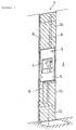
- An observation elevator is known which is provided on a side of the outer wall 101 of a building, as illustrated in Figure 6 of the accompanying drawings.
- Transparent glass 104 extends over the opening 103 on the outside of the hoistway 102.
- the cab 105 movable in the hoistway 102 has an observation window 106, and passengers can observe the outside scenery through this window and the glass 104.
- a conventionally driven rope 107 is attached to the top of the cage 105, and a travelling cable 108 for supplying power to the cage is connected to the bottom of the cage.
- a guideway having a carrier movable therealong, said carrier having a window
- said guideway including a light-adjusting medium having a see-through state and a non-see-through state, and means for maintaining said medium in said see-through state when in register with said window, so as to permit observation through said medium and said window as said carrier operates, and for maintaining said medium in said non-see-through state when not in register with said window.
- the said light-adjusting medium comprises liquid crystal glass having a coating to protect it from degradation by external light.
- the said guideway is of course the elevator hoistway and the carrier is the elevator cage.
- an alternating current power source is turned ON by means of the cage
- a liquid crystal light adjusting glass in a location corresponding to the observation window of the cage will be in a transparent state.
- the alternating current power source is turned OFF, and the liquid crystal light adjusting glass in a location where the cage is not present will be in a milky white opaque state.
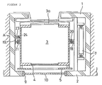
- a hoistway 1 is provided in the side of the outer wall 2 of a building, and an elevator cage 3 is installed in the hoistway.
- a plate 5 is attached to the cage to cover and hide the machinery and apparatus provided on the outer surface of the same, as is conventional.
- a rope 6 is attached to the top of the cage 3.
- This rope after running around the driving pulley of the hoist (not shown) located at the top of the hoistway 1, is attached to a counterweight 7 to balance the weight of the cage 3.
- This counterweight 7 is arranged in the hoistway 1 so as to be positioned next to the door 3a of the cage 3. Thus the counterweight is hidden by the outer wall 2, and is not visible from the outside.
- a travelling cable 8 is provided to supply electrical power to the cage.
- An opening 9 is defined vertically at the outer side of the hoistway 1. Substantially rectangular plates of liquid crystal light adjusting glass 10 are installed in this opening 9.
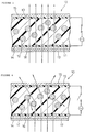
- the liquid crystal light adjusting glass 10 is, as illustrated in Figure 3 and as known in the art, composed of a mixture of resin 11 and liquid crystal 12, a pair of transparent polyester films 13, 14 with an electrically conductive film containing this mixture, and sheets of tempered glass 15 and 16 on the outside of the polyester films 13 and 14.
- the surface of the tempered glass 16 on the external side is coated with a UV filter 17 for the purpose of intercepting ultraviolet rays.
- the liquid crystal 12 When 100 v of alternating current is turned ON to the polyester films 13 and 14, the liquid crystal 12 will be in an aligned state, and light is transmitted. Thus the liquid crystal light adjusting glass 10 will be in a transparent, i.e. see-through, state. If the alternating current power is turned OFF, the liquid crystal 12 will be in an irregular arrangement as illustrated in Figure 4, and the light-will be scattered. Then, the liquid crystal light adjusting glass 10 will be in a milky white opaque, i.e. non-see-through, state.
- Liquid crystal 12 is subject to deterioration by the ultraviolet rays contained in sunlight. This deterioration is prevented by coating the tempered glass 16 with the UV filter 17.
- the cage 3 is guided vertically by a pair of guide rails 18 and 19 fixed vertically in the hoistway 1, via guide shoes 20 and 21.
- the guide rail 19 carries a series of photoelectric switches 23 connected to respective ones of the liquid crystal light adjusting glasses 10, via brackets 22.
- Each photoelectric switch 23 has a light projecting section 23a consisting of a light emitting diode or the like, and a light receiving section 23b consisting of a phototransistor or the like.
- a blade member 24 mounted on the cage 3 can locate between the light projection section 23a and the light receiving section 23b. If the blade member 24 is located in the optical path between the light projecting section 23a and the light intercepting section 23b, the photoelectric switch 23 will be in an ON state.
- a photoelectric switch 23 adjacent to it is turned ON by the blade member 24 mounted on the cage, and as a result the liquid crystal light adjusting glass 10 which is in line with the observation window 4 of the car will be in a transparent state.
- the photoelectric switch 23 in question is turned OFF, and the liquid crystal light adjusting glass 10 which the cage has now passed will be in a milky white opaque state.
- the quantity of direct sunlight entering the hoistway 1 is reduced considerably.
- the cost of air-conditioning the interior of the cage 3 in the summer can be reduced.
- the invention can also be applied to other types of elevator such as hydraulic elevators and linear motor type elevators.
Landscapes
- Engineering & Computer Science (AREA)
- Structural Engineering (AREA)
- Architecture (AREA)
- Civil Engineering (AREA)
- Physics & Mathematics (AREA)
- Electromagnetism (AREA)
- Mechanical Engineering (AREA)
- Automation & Control Theory (AREA)
- Types And Forms Of Lifts (AREA)
- Lift-Guide Devices, And Elevator Ropes And Cables (AREA)
- Cage And Drive Apparatuses For Elevators (AREA)
Applications Claiming Priority (2)
| Application Number | Priority Date | Filing Date | Title |
|---|---|---|---|
| JP22767392A JPH0672664A (ja) | 1992-08-27 | 1992-08-27 | 展望用エレベーターの昇降路 |
| JP227673/92 | 1992-08-27 |
Publications (1)
| Publication Number | Publication Date |
|---|---|
| EP0585123A1 true EP0585123A1 (de) | 1994-03-02 |
Family
ID=16864541
Family Applications (1)
| Application Number | Title | Priority Date | Filing Date |
|---|---|---|---|
| EP93306770A Withdrawn EP0585123A1 (de) | 1992-08-27 | 1993-08-26 | Schacht für einen Fassadenaufzug |
Country Status (3)
| Country | Link |
|---|---|
| EP (1) | EP0585123A1 (de) |
| JP (1) | JPH0672664A (de) |
| AU (1) | AU4487693A (de) |
Cited By (5)
| Publication number | Priority date | Publication date | Assignee | Title |
|---|---|---|---|---|
| EP0700858A1 (de) | 1994-09-08 | 1996-03-13 | Inventio Ag | Aufzug mit einer Verkleidung zur Einblicksverdeckung des Schachtes |
| FR2737200A1 (fr) * | 1995-07-25 | 1997-01-31 | Otis Elevator Co | Ascenseur de facade sans pylone |
| EP1354838A1 (de) * | 2002-04-15 | 2003-10-22 | Inventio Ag | Aufzug als Werbeträger und Aufzugkabine dafür |
| CN101734538B (zh) * | 2009-12-18 | 2012-09-19 | 日立电梯(中国)有限公司 | 观光梯井道的观光控制方法 |
| CN103072852A (zh) * | 2013-01-04 | 2013-05-01 | 日立电梯(中国)有限公司 | 观光电梯调光调温控制系统及其方法 |
Citations (5)
| Publication number | Priority date | Publication date | Assignee | Title |
|---|---|---|---|---|
| DE3324691A1 (de) * | 1983-07-08 | 1985-01-17 | Merck Patent Gmbh, 6100 Darmstadt | Elektrooptisches anzeigeelement |
| JPH01247386A (ja) * | 1988-03-28 | 1989-10-03 | Toshiba Corp | 展望用エレベータ昇降路壁の表示装置 |
| JPH0266090A (ja) * | 1988-08-31 | 1990-03-06 | Toshiba Corp | 展望用エレベータ装置 |
| JPH03102088A (ja) * | 1989-09-14 | 1991-04-26 | Toshiba Corp | 展望用エレベータ |
| DE9200004U1 (de) * | 1991-04-13 | 1992-03-26 | Diveg Deutsche Hotel-Investitionsgesellschaft mbH, 4300 Essen | Gebäude, insbesondere Hochhaus |
-
1992
- 1992-08-27 JP JP22767392A patent/JPH0672664A/ja not_active Withdrawn
-
1993
- 1993-08-24 AU AU44876/93A patent/AU4487693A/en not_active Abandoned
- 1993-08-26 EP EP93306770A patent/EP0585123A1/de not_active Withdrawn
Patent Citations (5)
| Publication number | Priority date | Publication date | Assignee | Title |
|---|---|---|---|---|
| DE3324691A1 (de) * | 1983-07-08 | 1985-01-17 | Merck Patent Gmbh, 6100 Darmstadt | Elektrooptisches anzeigeelement |
| JPH01247386A (ja) * | 1988-03-28 | 1989-10-03 | Toshiba Corp | 展望用エレベータ昇降路壁の表示装置 |
| JPH0266090A (ja) * | 1988-08-31 | 1990-03-06 | Toshiba Corp | 展望用エレベータ装置 |
| JPH03102088A (ja) * | 1989-09-14 | 1991-04-26 | Toshiba Corp | 展望用エレベータ |
| DE9200004U1 (de) * | 1991-04-13 | 1992-03-26 | Diveg Deutsche Hotel-Investitionsgesellschaft mbH, 4300 Essen | Gebäude, insbesondere Hochhaus |
Non-Patent Citations (3)
| Title |
|---|
| PATENT ABSTRACTS OF JAPAN vol. 13, no. 588 (M - 912) 25 December 1989 (1989-12-25) * |
| PATENT ABSTRACTS OF JAPAN vol. 14, no. 243 (M - 977) 23 May 1990 (1990-05-23) * |
| PATENT ABSTRACTS OF JAPAN vol. 15, no. 286 (M - 1138) 19 July 1991 (1991-07-19) * |
Cited By (6)
| Publication number | Priority date | Publication date | Assignee | Title |
|---|---|---|---|---|
| EP0700858A1 (de) | 1994-09-08 | 1996-03-13 | Inventio Ag | Aufzug mit einer Verkleidung zur Einblicksverdeckung des Schachtes |
| AU698262B2 (en) * | 1994-09-08 | 1998-10-29 | Inventio Ag | Lift with a lift cage |
| FR2737200A1 (fr) * | 1995-07-25 | 1997-01-31 | Otis Elevator Co | Ascenseur de facade sans pylone |
| EP1354838A1 (de) * | 2002-04-15 | 2003-10-22 | Inventio Ag | Aufzug als Werbeträger und Aufzugkabine dafür |
| CN101734538B (zh) * | 2009-12-18 | 2012-09-19 | 日立电梯(中国)有限公司 | 观光梯井道的观光控制方法 |
| CN103072852A (zh) * | 2013-01-04 | 2013-05-01 | 日立电梯(中国)有限公司 | 观光电梯调光调温控制系统及其方法 |
Also Published As
| Publication number | Publication date |
|---|---|
| JPH0672664A (ja) | 1994-03-15 |
| AU4487693A (en) | 1994-03-03 |
Similar Documents
| Publication | Publication Date | Title |
|---|---|---|
| FI95456C (fi) | Järjestely hissikuilun seinän aukossa ja kojetaulu | |
| AU6595694A (en) | Traction sheave elevator with drive machine below | |
| EP0779233A3 (de) | Antriebsscheibenaufzug | |
| CN1044996C (zh) | 牵引滑轮电梯、提升机构和设备容置室 | |
| EP0585123A1 (de) | Schacht für einen Fassadenaufzug | |
| US7299896B1 (en) | Elevator system having drive motor located adjacent to hoistway door | |
| JPH07172738A (ja) | 展望用エレベーター |
Legal Events
| Date | Code | Title | Description |
|---|---|---|---|
| PUAI | Public reference made under article 153(3) epc to a published international application that has entered the european phase |
Free format text: ORIGINAL CODE: 0009012 |
|
| AK | Designated contracting states |
Kind code of ref document: A1 Designated state(s): FR GB |
|
| 17P | Request for examination filed |
Effective date: 19940801 |
|
| 17Q | First examination report despatched |
Effective date: 19951026 |
|
| STAA | Information on the status of an ep patent application or granted ep patent |
Free format text: STATUS: THE APPLICATION IS DEEMED TO BE WITHDRAWN |
|
| 18D | Application deemed to be withdrawn |
Effective date: 19960506 |