EP0585258B1 - Soupape rotative pour direction assistee de vehicules - Google Patents
Soupape rotative pour direction assistee de vehicules Download PDFInfo
- Publication number
- EP0585258B1 EP0585258B1 EP92909363A EP92909363A EP0585258B1 EP 0585258 B1 EP0585258 B1 EP 0585258B1 EP 92909363 A EP92909363 A EP 92909363A EP 92909363 A EP92909363 A EP 92909363A EP 0585258 B1 EP0585258 B1 EP 0585258B1
- Authority
- EP
- European Patent Office
- Prior art keywords
- rotary valve
- input
- sleeve
- shaft
- valve
- Prior art date
- Legal status (The legal status is an assumption and is not a legal conclusion. Google has not performed a legal analysis and makes no representation as to the accuracy of the status listed.)
- Expired - Lifetime
Links
Images







Classifications
-
- B—PERFORMING OPERATIONS; TRANSPORTING
- B62—LAND VEHICLES FOR TRAVELLING OTHERWISE THAN ON RAILS
- B62D—MOTOR VEHICLES; TRAILERS
- B62D6/00—Arrangements for automatically controlling steering depending on driving conditions sensed and responded to, e.g. control circuits
- B62D6/02—Arrangements for automatically controlling steering depending on driving conditions sensed and responded to, e.g. control circuits responsive only to vehicle speed
-
- B—PERFORMING OPERATIONS; TRANSPORTING
- B62—LAND VEHICLES FOR TRAVELLING OTHERWISE THAN ON RAILS
- B62D—MOTOR VEHICLES; TRAILERS
- B62D5/00—Power-assisted or power-driven steering
- B62D5/06—Power-assisted or power-driven steering fluid, i.e. using a pressurised fluid for most or all the force required for steering a vehicle
- B62D5/08—Power-assisted or power-driven steering fluid, i.e. using a pressurised fluid for most or all the force required for steering a vehicle characterised by type of steering valve used
- B62D5/083—Rotary valves
-
- Y—GENERAL TAGGING OF NEW TECHNOLOGICAL DEVELOPMENTS; GENERAL TAGGING OF CROSS-SECTIONAL TECHNOLOGIES SPANNING OVER SEVERAL SECTIONS OF THE IPC; TECHNICAL SUBJECTS COVERED BY FORMER USPC CROSS-REFERENCE ART COLLECTIONS [XRACs] AND DIGESTS
- Y10—TECHNICAL SUBJECTS COVERED BY FORMER USPC
- Y10T—TECHNICAL SUBJECTS COVERED BY FORMER US CLASSIFICATION
- Y10T137/00—Fluid handling
- Y10T137/8593—Systems
- Y10T137/86493—Multi-way valve unit
- Y10T137/86574—Supply and exhaust
- Y10T137/86638—Rotary valve
- Y10T137/86646—Plug type
- Y10T137/86654—For plural lines
-
- Y—GENERAL TAGGING OF NEW TECHNOLOGICAL DEVELOPMENTS; GENERAL TAGGING OF CROSS-SECTIONAL TECHNOLOGIES SPANNING OVER SEVERAL SECTIONS OF THE IPC; TECHNICAL SUBJECTS COVERED BY FORMER USPC CROSS-REFERENCE ART COLLECTIONS [XRACs] AND DIGESTS
- Y10—TECHNICAL SUBJECTS COVERED BY FORMER USPC
- Y10T—TECHNICAL SUBJECTS COVERED BY FORMER US CLASSIFICATION
- Y10T137/00—Fluid handling
- Y10T137/8593—Systems
- Y10T137/86493—Multi-way valve unit
- Y10T137/86574—Supply and exhaust
- Y10T137/86638—Rotary valve
- Y10T137/86646—Plug type
- Y10T137/86662—Axial and radial flow
Definitions
- This invention relates to hydraulic power steering gears for motor vehicles and, in particular to the rotary valves used in such steering gears, such as defined in the preamble of claim 1 and known for example from US-A-4774847
- rotary valves for hydraulic power steering include an input-shaft, usually connected to the steering wheel of the vehicle by a flexible joint, and having in its outer periphery a plurality of blind ended, axially extending grooves separated by lands.
- Journalled on the input-shaft is a sleeve having in its bore an array of axially extending blind ended slots matching the grooves in the input-shaft, but in underlap relationship thereto, the slots of the one being wider than the lands of the other so defining a set of axially extending orifices which open and close when relative rotation occurs between the input-shaft and the sleeve.
- These orifices are ported as a network such that they form sets of hydraulic Wheatstone bridges which act in parallel.
- Drilled passages in the input-shaft and sleeve together with circumferential grooves in the periphery of the sleeve, serve to communicate oil between the grooves in the input-shaft and the slots in the sleeve, an engine driven oil pump, and right-hand and left-hand hydraulic assist cylinder chambers incorporated in the steering gear.
- a torsion bar incorporated in the input-shaft serves to urge the input-shaft and sleeve towards a neutral, centred condition when no power assistance is required.
- the torsion bar deflects, causing relative rotation of the sleeve and input-shaft from the neutral condition.
- This so called “valve operating angle” imbalances the sets of hydraulic Wheatstone bridges and hence causes a differential pressure to be developed between the right-hand and left-hand hydraulic assist cylinder chambers.
- the "boost characteristic" of the rotary valve that is the functional relationship between the above mentioned input torque and differential pressure, is determined for a given steering gear application by the geometry of axially extending contours formed on the edges of the grooves of the input-shaft adjacent to its outside diameter.
- Pressure modulated centring mechanisms have been used in some prior art speed sensitive valve systems to progressively increase steering efforts with vehicle speed and are of three main types.
- This constant centring torque algebraically adds to the linearly increasing centring torque of the torsion bar and can be modulated by varying the magnitude of the hydraulic pressure via a control valve.
- Such arrangements add substantial axial length, typically 20mm, to the rotary valve.
- substantial axial length typically 20mm
- Hertzian stresses will be involved, tending to limit the working life of such a device.
- Extreme precision in locating the notches in the opposed plungers is required if a "dead area" of response is to be avoided in on-centre driving.
- the detent action is similar to the previous case except that, because no rolling takes place, a large amount of friction occurs at the sliding detent interface which produces corresponding hysteresis in the valve boost characteristic. This friction, exacerbated by again the high Hertzian contact stresses characteristic of the essentially point contact between the balls and notches, will tend to generate high levels of wear and hence fast degradation of the contact surfaces.
- Prior art mechanical centring mechanisms are all aimed at providing such a constant threshold input torque, typically 0.5-1.0 Nm to null any torsion bar deflection during on-centre driving, and require no additional hydraulic sub-systems for their actuation. Again they fall into three major categories.
- C-spring arrangements have the disadvantage that their deflection must encompass not only the entire normal valve operation angle (typically +/- 4 degrees) but must be designed not to be overstressed at the so called "fail safe" angle (typically +/- 7 degrees).
- This large fail safe angle is determined by a lost-motion drive arrangement in conventional rotary valves which mechanically limits valve operating angle in the event of torsion bar breakage or loss of hydraulic supply from the pump.
- the C-spring In order that the C-spring provide the earlier stated threshold input torque of 0.5-1.0 Nm, it must be axially long (measured parallel to the axis of the rotary valve) in order to avoid overstressing at the fail safe angle of about 7 degrees, and therefore results in additional axial length of the rotary valve.
- the input-shaft must be essentially tubular in order to accommodate the assembly's diameter (typically about 16mm). To date this arrangement has been employed in ZF valves with a 22 mm input-shaft outside diameter. It would be difficult to miniaturise the assembly further so that it could be employed in the majority of power steering valves which employ input-shafts with less than 21 mm outside diameter. Also, again the use of miniature balls to achieve the detent action results in high Hertzian contact stresses.
- German Patent 3,013,535 Jablonsky
- a diametrically disposed column of sheet steel which axially deforms by buckling when an input torque exceeding a given threshold is applied to the input-shaft.
- This threshold is determined by the kinematics of the mechanism and the column strength of the sheet steel element.
- the appropriate centring torque which is relatively large up to the point of buckling, then reduces as progressive buckling deformation occurs.
- Buckling is, by its very nature, a difficult phenomena to accurately analytically predict and is very much a function of parameters which, in a production environment, will be very hard to control. For example, as acknowledged in the patent itself, any small preset bend in the column element will drastically reduce the buckling strength of this element and therefore reduce the resulting threshold input-torque. For these reasons we believe this mechanism has never been utilized in production.
- the aim of the present invention is to provide a centring mechanism capable of incorporation into a conventional speed sensitive or non speed sensitive rotary valve of standard outside diameter, typically about 37.5mm.
- the device should also introduce minimum additional length to the rotary valve and be useable as an "add on” or optional feature to improve the on-centre performance of an otherwise standard format rotary valve.
- the centring mechanism is aimed at preloading the valve to its neutral condition up to a threshold input torque of 0.5 - 1.0 Nm (approximately) consistent with on-centre driving. Precision and feel under these circumstances will only be optimized if valve friction is also absolutely minimized.
- An entirely mechanical detent system employing only rolling contact is consistent with this aim and is therefore one element of this invention.
- the present invention consists in a rotary valve for a power steering gear comprising an input-shaft, a sleeve, a driven member and an entirely mechanically actuated centring mechanism, the centring mechanism comprising one or more rolling elements, each disposed between a pair of opposed notched elements, one notched element of each pair being rotationally fixed with respect to or integral with the input-shaft and the other notched element of each pair being rotationally fixed with respect to or integral with the sleeve or the driven member, each pair of opposed notched elements being urged together by spring means to trap one of the rolling elements between them, thereby producing a detent action between the input-shaft and the sleeve or driven member, whereby relative rotation occurs between the input-shaft and the sleeve or driven member only upon application of an input torque exceeding a predetermined threshold, characterised in that, after the predetermined threshold input torque has been exceeded, each rolling element rolls between opposite surface contours of the pair of opposed notched elements, the contours each including a convex
- the geometry of the notches, and the appropriate decrease in centring torque has the effect of limiting the deflection of the springs, compared to the prior art cases where the notches are triangular in shape and hence result in no such decrease. This consequentially limits the strain energy needed to be stored in the springs and hence permits a practical, more compact, design of such springs.
- the rolling element is cylindrical in shape and makes essentially line contact with prismoidally shaped notches in the notched elements. This reduces the Hertzian stresses between the contour of the notches and a given diameter rolling element, and hence considerably reduces the diameter of the rolling element compared to an equivalently stressed spherical element.
- the contour of the notches may be chosen to have a substantially smaller radius than that of the rolling element, even approaching a sharp edged contour, yet the stresses at the point of contact will not exceed the limit for practical engineering materials (for example, hardened steel).
- the geometry of the notch contours is V-shaped up to the point immediately adjacent to the line of contact with the rolling element when the detent is centred.
- the rolling element rolls around a small radius on the contour and results in the locus of the centre of the rolling element being arcuate at a radius only slightly larger than that of the rolling element.
- the centring mechanism is arranged with the detent acting essentially radially with respect to the central axis of the rotary valve and the axes of the cylindrical rolling elements, and the corresponding prismatic notches of the notched elements, arranged parallel with this axis.
- the centring mechanism can be positioned at either end of the sleeve and arranged to act directly between the input-shaft and sleeve to augment the torsion bar.
- the input-shaft incorporates two diametrically opposed, axially aligned notches on its outside diameter, and forms the inner notched element.
- the carrier is positioned on the end face of the sleeve and this carrier includes two diametrically opposed, radially extending grooves.
- Each such groove incorporates a rectangular notched plunger which radially slides in the groove with virtually zero side clearance.
- a rolling element is trapped between the notch in each plunger and the adjacent notch on the outside diameter of the input-shaft.
- Two crescent shaped arms are located in a circumferential groove which extends around the outside diameter of the carrier. The centre of each arm contacts the radially outermost face on each plunger. Hooks formed on the extremities of each arm are respectively connected by coil tension springs which urge the two arms and, hence, the two plungers mutually towards the centre axis of the valve.
- This arrangement packages within the cylindrical surface defined by the outside diameter of a standard sleeve and adds minimum additional length to the rotary valve. It can therefore be included as an "add-on" or optional feature to improve the stiffness and feel of a standard rotary valve.
- the carrier is flat faced and attached to the end face of the sleeve by screws, or other securing means.
- the notched plungers are loaded radially inwardly by two C springs which contact the radially outermost face of the plungers.
- the notched plungers, rolling elements and C springs are axially restrained via a cover plate which also acts as a non rotating washer and locking tab for the attachment screws.
- the mounting holes in the carrier are large compared to the major diameter of the attachment screws, or other fixing means, and therefore a small degree of "float" is possible of this carrier with respect to the end face of the sleeve, both radially and also rotationally prior to securing.
- Fig. 1 shows the valve assembly incorporating input-shaft 1 journalled inside sleeve 2 and resiliently connected to pinion 3 (the driven member) by torsion bar 4.
- Sleeve 2 is rotationally connected to pinion 3 by sleeve drive pin 5, while torsion bar 4 is fixed at its left end to input-shaft 1 by torsion bar pin 6 and fixed at its right end to pinion 3 by swaged connection 7. Therefore an input torque applied at input-shaft 1 angularly deflects torsion bar 4 and causes relative angular displacement between input-shaft 1 and sleeve 2, known as the valve operating angle.
- the manner in which this valve operating angle serves to produce the hydraulic assistance in the steering gear, and thus impart an axial output force to rack 8, is well understood by persons knowledgeable in the art of power assisted steering gears and will not be detailed further in this description.
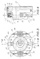
- the valve assembly also incorporates centring mechanism 9 mounted on the end of sleeve 2 remote from pinion 3. This mechanism is shown in more detail in Figs. 2, 3 and 4. Centring mechanism 9 is arranged to act directly between input-shaft 1 and sleeve 2 to produce a centring torque between these elements which augments the linear centring torque derived from torsion bar 4.
- Input-shaft 1 incorporates two diametrically opposed, axially aligned, prismatic notches 10 on its outside diameter.
- Carrier 11 is positioned against end face 12 of sleeve 2 and centralized on external spigot 13 by the engagement with cylindrical flange 14 of carrier 11.
- Carrier 11 includes two diametrically opposed, radially extending grooves 17, each groove 17 incorporating a rectangular notched plunger 18 which radially slides along the parallel side faces 19 of groove 17 with virtually zero clearance.
- Prismatic notches 20 in the radially innermost faces of plungers 18 are also axially aligned with the central valve axis 21.
- Cylindrical rollers 22 are trapped between notch 20 in each plunger 18 and the adjacent notch 10 on the outside diameter of input-shaft 1.
- Each arm 23 is located in a circumferential groove 24 which extends around the outside diameter of carrier 11, intersecting with radially extending grooves 17.
- the central inside surface of each arm 23 includes a small recess 25 which keys into groove 26 in the radially outermost face of plunger 18.
- Hooks 27 are formed on the extremities of each arm 23 and support tension coil springs 28 which connect adjacent hooks on opposed arms 23, thereby urging together arms 23 and, hence, also opposed plungers 18.
- U-shaped clips 29 retain cylindrical rollers 22 axially, and also serve to hold the entire centring mechanism together as a single unit to facilitate assembly onto the rotary valve during manufacture.
- each cylindrical roller 22 loads each cylindrical roller 22 between its respective notch 20 in plunger 18 and its adjacent notch 10 on the outside diameter of input-shaft 1 as a rolling action detent.
- four-line contact occurs on each cylindrical roller 22 as at contact points 30 a-d in Fig. 5a.
- the contour of the respective notch 10 or 20 is tangential to the cylindrical surface of cylindrical roller 22 and, with knowledge of the actual geometry of the detent and remaining componentry of centring mechanism 9, enables simple calculation of the threshold input torque.
- Fig. 6 plots the locus of centre 33 of cylindrical roller 22 as it is displaced either side of the neutral condition.
- cylindrical roller 22 rolls to the left, relative to input-shaft notch 10, through positions 33, 33a, 33b and 33c.
- position 33a corresponds to that position shown in Fig. 5b where cylindrical roller 22 is about to abut against side face 19 of carrier 11, however further positions 33b and 33c are also quite practical depending upon the actual type of detent action required.
- cylindrical roller 22 rolls to the right, relative to input-shaft notch 10, through positions 33, 33d, 33e and 33f.
- portions of locus 33-33b and 33-33e are approximately arcuate about these points respectively, and effectively limit the radial rise of centre 33 of cylindrical roller 22 to distance 35.
- distance 35 is many times less than distance 36 which corresponds to the radial rise of centre 33 of cylindrical roller 22 if a simple triangular notch was employed, as in prior art mechanical centring mechanisms.
- deflection of springs 28 is considerably reduced, enabling them to be packaged into carrier 11 mounted on the end face of sleeve 2.
- Fig. 7 plots the corresponding relationship of centring torque as a function of valve operating angle, when combined with the linear action of the torsion bar.
- This combined relationship is plotted as curve 37-37c, the latter point corresponding to the typical rotary valve fail safe angle F of 7 degrees.
- the centring force contributed by the centring mechanism is maximum when the valve is in its on-centre or neutral condition, and corresponds to the threshold input torque T as at point 37.
- This centring torque attenuates with the reduction of angle 32 to zero at point 37b where no further torsion bar augmentation occurs up to the fail safe angle F at point 37c.
- line 37b-37c is colinear with line 38, corresponding to the simple linear relationship for the torsion bar only.
- curve 37-37b will tend to bulge upwards indicated as alternative curve 39. This situation is not critical provided that the overall slope of centring torque relationship is always monotonic increasing, as is the case shown. If extremely stiff springs 28 are used in the system curve 39 bulges further to the extent shown as curve 40, resulting in negative slope in the region 41. This will lead to unstable rotary valve actuation, and result in non-continuous increase in valve operating angle for progressive application of input torque by the driver.
- the near-sharp-edged contour shown in Fig. 6 is optimum in terms of limiting the radial rise distance 35 of centre 33 of cylindrical roller 22.
- the use of a cylindrical roller, as compared with a spherical member, has the effect of distributing loads along the lines of contact 30a-30d and therefore permitting such near-sharp-edges. If a particular material requirement limits the possible Hertzian stresses to the degree that such near-sharp-edges on the contours of notches 10 and 20 are not feasible, an alternative arrangement can be employed shown in Fig. 8.
- near-sharp-edges 30a and 30b are replaced by prismatic fillet radii 43a and 43b and the new locus 44 of the centre 33 of cylindrical roller 22 is now arcuate about the centres 45 and 46 of these fillet radii.
- the radial rise of axis 33, and hence the overall deflection of springs 28 will be increased slightly to a distance 45, however the Hertzian contact stresses will be considerably reduced.
- a slightly smaller roller may be used, preserving the kinematics of Fig. 6.
- a contour of varying radius could be employed on the notches, as shown as contour 46 in Fig. 9.
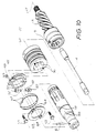
- input-shaft 50, prismatic notches 51, and cylindrical rollers 52 are substantially the same as for the earlier described first embodiment, and correspond to items 1, 10 and 22 respectively in Figs. 2-9.
- Carrier 53 is flat faced and attached to sleeve 54 by two hexagonal headed screws 55 engaged in drilled and tapped holes 56 in the end face of sleeve 54.
- Rectangular notched plungers 57 again radially slides along the parallel side faces 58 of grooves 59 in carrier 53 with virtually zero clearance.
- the doubly trapped rolling action, resulting from geometry of prismatic notches 51 and 60 (the latter in notched plungers 57) and cylindrical rollers 52 is exactly the same as for the case of the first embodiment.
- notched plungers 57 also includes radiused dead stops 61 which, as in the case of side faces 19 in the first embodiment, serve to correct misorientation and limit the travel of cylindrical rollers 52.
- notched plungers 57 are loaded radially inwardly, not by coil springs 28 as in the first embodiment, but by two C springs 62 supported on contoured portion 63 of notched plungers 57.
- Axial restraint of cylindrical rollers 52, notched plungers 57 and C springs 62 is via cover plate 63.
- Cover plate 63 also acts as a non rotating washer for hexagonal headed screws 55 and also facilitates locking of these screws via tabs 64.
- C springs 62 although shown as being of uniform thickness, are of varying width measured in the axial direction. According to usual practice in the design of C springs, greatest width is used in their central region where maximum bending moment is to be sustained whereas their extremities, adjacent to their point of contact with contoured portion 63 of notched plungers 57, is subject to lesser bending moment and can therefore afford to be narrower. In this manner bending stresses are more uniformly distributed in the C spring compared to if the C spring was of uniform width and, for a given maximum stress level, provides minimum spring rate.
- the symmetrically disposed C spring arrangement ensures minimum side loading between side faces 58 of grooves 59 and the sliding surfaces of notched plungers 57, thereby minimising friction and wear. It is, of course, possible that for certain applications the resilient member could consist of only a single C spring.
- the C spring could be manufactured from a single sheet of spring steel or, alternatively, multilayered or leaved.
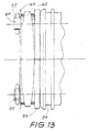
- notched plungers could be employed in the mechanical detent mechanism, mutually radially disposed at approximately 120 degrees around the input-shaft.
- Three C springs would then be used to mutually interconnect these plungers thereby avoiding any of the aforementioned side loading (refer to Fig. 14).
- four notched plungers could be radially disposed at approximately 90 degrees around the input-shaft with an appropriate set of four C springs.
- the larger the number of plungers and C springs the less the space or "footprint" available for the mounting screws. For applications to date, two plungers (and two C springs) have been found optimum.
- a particular feature of this second embodiment is the means by which the centring mechanism may be made to be aligned perfectly during the attachment of carrier 53 to sleeve 54. It is, of course, ideally necessary that the centring mechanism is precisely rotationally matched to the centring torque supplied by torsion bar 4, and that, when this torsion bar centring torque is zero, the opposed cylindrical rollers 52 are engaged in 4-line contact with the detent notches, (ie. 2-line contact with each prismatic notch 51 and 60). For this to be possible consistent with normal engineering tolerances on such components, carrier 53 must be capable of fine adjustment both rotationally (ie. in direction E) and radially (ie. in direction C or D or in a combination thereof) prior to final securing.
- the two large locating holes 65 in carrier 53 are a clearance fit compared to the major diameter of the threads of screws 55. Hence, if screws 55 are relaxed as during assembly, the entire mechanism will assume this ideal condition. Thereafter screws 55 are tightened to rigidly secure carrier 53 to sleeve 54. Tabs 64 of cover plate 63 are then deformed around the hexagonal heads of screws 55 for permanently locking these screws during the service life of the steering gear.
- the matching of the centring device with the torsion bar must be accomplished by a precise centring technique, and the centring action of the opposing (or even four) separate detents must be made to coincide through extreme precision of manufacture not required in the second embodiment just described.
Landscapes
- Engineering & Computer Science (AREA)
- Chemical & Material Sciences (AREA)
- Combustion & Propulsion (AREA)
- Transportation (AREA)
- Mechanical Engineering (AREA)
- Power Steering Mechanism (AREA)
Abstract
Claims (10)
- Un tiroir rotatif pour une direction assistée comprenant un arbre d'entrée (1;50), un manchon (2;54), un élément commandé (3) et un mécanisme de centrage actionné de manière intégralement mécanique (9), le mécanisme de centrage comprenant un ou plusieurs éléments de roulement (22;52), chacun disposé entre une paire d'éléments entaillés opposés, un élément entaillé (10;51) de chaque paire étant fixé en rotation par rapport ou faisant partie intégrante de l'arbre d'entrée (1;50) et l'autre élément entaillé (18,20;57,60) de chaque paire étant fixé en rotation par rapport ou faisant partie intégrante du manchon (2;54) ou de l'élément commandé, chaque paire d'élément entaillé opposé étant pressé ensemble à l'aide de moyens de ressort (28;62) pour emprisonner un des éléments de roulement (22;52) entre eux, en produisant ainsi une action de détente entre l'arbre d'entrée et le manchon ou l'élément commandé, de sorte qu'il se produit une rotation relative entre l'arbre d'entrée et le manchon ou l'élément commandé uniquement après application d'un couple d'entrée dépassant un seuil prédéterminé, caractérisé en ce que, après que le couple d'entrée de seuil prédéterminé a été franchi, chaque élément de roulement (22; 52) roule entre des contours de surface opposés de la paire d'éléments opposés entaillés (10,18,20;51,57,60), chacun des contours comprenant une surface convexe, dont la forme est telle qu'il est produit un couple de centrage entre l'arbre d'entrée (1;50) et le manchon (2;54) ou l'élément commandé, lequel diminue pour des augmentations de valeur de rotation s'éloignant d'un état neutre du tiroir rotatif.
- Un tiroir rotatif comme revendiqué à la revendication 1, dans lequel les éléments de roulement (22;52) sont cylindriques et sont en contact linéaire avec des contours de forme prismatique prévus dans les éléments entaillés.
- Un tiroir rotatif comme revendiqué à la revendication 2, dans lequel les éléments de roulement (22;52) sont disposés parallèlement à un axe central (21) du tiroir rotatif.
- Un tiroir rotatif comme revendiqué à la revendication 1, dans lequel le lieu du centre de chaque élément de roulement (22;52) au cours d'une rotation relative est une courbe présentant un rayon essentiellement égal au rayon de l'élément de roulement mais le dépassant légèrement.
- Un tiroir rotatif comme revendiqué à la revendication 1, dans lequel les surfaces convexes des contours des éléments entaillés (10,18,20;51,57,60) deviennent parallèles à la direction du déplacement relatif entre l'arbre d'entrée et le manchon ou l'élément commandé à des angles de fonctionnement de tiroir élevés non associés à une conduite au centre.
- Un tiroir rotatif comme revendiqué à la revendication 1, dans lequel les forces produites par ledit moyen de ressort (28;62) pour produire une action de détente, agissent dans une direction essentiellement radiale par rapport à un axe central (21) du tiroir rotatif.
- Un tiroir rotatif comme revendiqué à la revendication 6, dans lequel chaque paire d'éléments entaillés se compose d'un premier élément formé sur un piston (18;57) porté sur un support (11;53) fixé à une face d'extrémité du manchon ou de l'élément commandé et monté pour un déplacement radial par rapport à l'arbre d'entrée et d'un deuxième élément constitué d'une entaille (10;51) formé dans la surface de l'arbre d'entrée.
- Un tiroir rotatif comme revendiqué à la revendication 7, dans lequel les pistons (18) sont espacés diamétralement et le moyen de ressort est constitué d'un ou de plusieurs ressorts bobinés (28) disposés pour appliquer une charge sur chaque piston.
- Un tiroir rotatif comme revendiqué à la revendication 7, dans lequel les pistons (57) sont espacés diamétralement et le moyen de ressort est constitué d'un ou de plusieurs ressorts en C (62) disposés pour agir entre des pistons opposés.
- Un tiroir rotatif comme revendiqué à la revendication 7, dans lequel il existe trois pistons ou davantage espacés circonférenciellement autour de l'arbre d'entrée, et le moyen de ressort est constitué d'une pluralité de ressorts en C, chacun agissant sur des pistons adjacents.
Applications Claiming Priority (3)
| Application Number | Priority Date | Filing Date | Title |
|---|---|---|---|
| AUPK633391 | 1991-05-24 | ||
| AU6333/91 | 1991-05-24 | ||
| PCT/AU1992/000196 WO1992020561A1 (fr) | 1991-05-24 | 1992-04-30 | Soupape rotative pour direction assistee de vehicules |
Publications (3)
| Publication Number | Publication Date |
|---|---|
| EP0585258A1 EP0585258A1 (fr) | 1994-03-09 |
| EP0585258A4 EP0585258A4 (en) | 1994-07-27 |
| EP0585258B1 true EP0585258B1 (fr) | 1996-11-13 |
Family
ID=3775430
Family Applications (2)
| Application Number | Title | Priority Date | Filing Date |
|---|---|---|---|
| EP92909363A Expired - Lifetime EP0585258B1 (fr) | 1991-05-24 | 1992-04-30 | Soupape rotative pour direction assistee de vehicules |
| EP92909368A Expired - Lifetime EP0585259B1 (fr) | 1991-05-24 | 1992-04-30 | Soupape rotative pour direction assistee |
Family Applications After (1)
| Application Number | Title | Priority Date | Filing Date |
|---|---|---|---|
| EP92909368A Expired - Lifetime EP0585259B1 (fr) | 1991-05-24 | 1992-04-30 | Soupape rotative pour direction assistee |
Country Status (9)
| Country | Link |
|---|---|
| US (2) | US5233906A (fr) |
| EP (2) | EP0585258B1 (fr) |
| JP (2) | JP3044273B2 (fr) |
| KR (1) | KR100237965B1 (fr) |
| BR (2) | BR9205756A (fr) |
| CA (2) | CA2100668C (fr) |
| DE (2) | DE69215219T2 (fr) |
| ES (2) | ES2107533T3 (fr) |
| WO (2) | WO1992020561A1 (fr) |
Families Citing this family (30)
| Publication number | Priority date | Publication date | Assignee | Title |
|---|---|---|---|---|
| ES2036126B1 (es) * | 1991-04-19 | 1993-12-16 | Bendix Espana | Distribuidor hidraulico rotativo. |
| US5361861A (en) * | 1993-01-29 | 1994-11-08 | Trw Inc. | Power steering system |
| JPH072125A (ja) * | 1993-04-22 | 1995-01-06 | Toyota Motor Corp | パワーステアリング用トーションバー |
| DE4315895B4 (de) * | 1993-05-12 | 2008-04-03 | Zf Friedrichshafen Ag | Lenkkraftverstärker |
| US5465805A (en) * | 1993-09-03 | 1995-11-14 | Trw Inc. | Power steering system |
| DE4420746C2 (de) * | 1994-06-15 | 1997-10-02 | Trw Fahrwerksyst Gmbh & Co | Lenkventil |
| US5697400A (en) * | 1995-06-29 | 1997-12-16 | Trw Fahrwerksysteme Gmbh & Co. Kg | Steering valve |
| US5707049A (en) * | 1995-10-23 | 1998-01-13 | General Motors Corporation | Power steering gear for motor vehicle |
| AUPN628895A0 (en) | 1995-10-31 | 1995-11-23 | A.E. Bishop & Associates Pty Limited | Component and method of manufacture thereof |
| KR970036864U (ko) * | 1995-12-27 | 1997-07-26 | 자동차용 유압제어 밸브의 구조 | |
| JP3728367B2 (ja) * | 1996-07-10 | 2005-12-21 | カヤバ工業株式会社 | パワーステアリング装置 |
| US5964315A (en) * | 1996-08-02 | 1999-10-12 | Kayaba Industry Co., Ltd. | Power steering apparatus |
| JP3728371B2 (ja) * | 1997-03-05 | 2005-12-21 | カヤバ工業株式会社 | パワーステアリング装置 |
| KR100470318B1 (ko) * | 1997-06-11 | 2005-07-01 | 고요 세이코 가부시키가이샤 | 동력보조스티어링기어용서보밸브 |
| JP3677383B2 (ja) * | 1997-06-19 | 2005-07-27 | カヤバ工業株式会社 | パワーステアリング装置 |
| US6026858A (en) * | 1997-12-10 | 2000-02-22 | Trw Inc. | Power steering assembly |
| US6237464B1 (en) * | 1998-01-16 | 2001-05-29 | Trw Inc. | Centering mechanism for a power steering control valve |
| US5957027A (en) * | 1998-09-30 | 1999-09-28 | Trw Inc. | Detent mechanism for a hydraulic power steering gear |
| KR100375992B1 (ko) * | 1998-11-04 | 2003-06-18 | 주식회사 만도 | 자동차용 조향장치의 액티브 센터 필 구조 |
| US6079289A (en) * | 1998-11-10 | 2000-06-27 | Trw Inc. | Detent mechanism for a hydraulic power steering gear |
| US6250334B1 (en) * | 1998-12-21 | 2001-06-26 | Ina Walzlager Schaeffler Ohg | Centering device for steering valves |
| US6202694B1 (en) | 1999-03-24 | 2001-03-20 | Trw Inc. | Detent mechanism for a hydraulic power steering gear |
| KR100401073B1 (ko) * | 1999-11-23 | 2003-10-10 | 주식회사 만도 | 자동차용 조향장치의 액티브 센터 필 구조 |
| US6854343B2 (en) * | 2001-06-29 | 2005-02-15 | Tyco Electronics Amp Gmbh | Torque sensor for electric power-assisted steering systems |
| US7143683B2 (en) * | 2003-09-24 | 2006-12-05 | Koyo Seiko Co., Ltd. | Hydraulic power steering apparatus |
| KR100514409B1 (ko) * | 2004-03-22 | 2005-09-09 | 현대모비스 주식회사 | 자동차 안티 록 브레이크 시스템의 펌프 |
| DE102006058157A1 (de) * | 2006-12-09 | 2008-06-12 | Zf Lenksysteme Gmbh | Servoventil |
| US7819948B2 (en) * | 2007-10-29 | 2010-10-26 | Air Products And Chemicals, Inc. | Rotary valve |
| US7819222B2 (en) * | 2008-02-08 | 2010-10-26 | Yh America, Inc. | Device and method for attenuating energy along a conduit |
| US7857003B2 (en) * | 2008-03-27 | 2010-12-28 | Sauder-Danfoss Inc. | Selectable detent assembly with neutral protection |
Family Cites Families (18)
| Publication number | Priority date | Publication date | Assignee | Title |
|---|---|---|---|---|
| GB1470975A (en) * | 1973-07-18 | 1977-04-21 | Cam Gears Ltd | Power assisted steering system |
| GB2044697B (en) * | 1979-03-20 | 1983-09-14 | Cam Gears Ltd | Valve assembly for power assisted steering gears |
| DE3013535A1 (de) * | 1980-04-08 | 1981-10-15 | Erich 7071 Böbingen Jablonsky | Hilfskraftlenkung fuer kraftfahrzeuge |
| ES8206320A1 (es) * | 1981-10-14 | 1982-08-16 | Bendiberica Sa | Perfeccionamientos en distribuidores hidraulicos rotativos. |
| JPH0696387B2 (ja) * | 1983-06-10 | 1994-11-30 | 三菱自動車工業株式会社 | パワーステアリング装置 |
| GB2165502B (en) * | 1984-10-12 | 1987-10-14 | Trw Cam Gears Ltd | A power-assisted steering gear |
| JPH0657532B2 (ja) * | 1985-10-19 | 1994-08-03 | 光洋精工株式会社 | 油圧動力補助操舵装置の自動直進復帰装置 |
| US4774847A (en) * | 1985-10-21 | 1988-10-04 | Zahnradfabrik Friedrichshafen, Ag. | Mechanism for centering relatively rotative components, particularly in rotary valves |
| EP0242389A1 (fr) * | 1985-10-21 | 1987-10-28 | ZF FRIEDRICHSHAFEN Aktiengesellschaft | Soupape a tiroir rotatif, en particulier pour servo-directions de vehicules a moteur |
| GB2199000B (en) * | 1986-12-19 | 1990-09-26 | Trw Cam Gears Ltd | A valve assembly for a power assisted steering system |
| US4759420A (en) * | 1987-07-16 | 1988-07-26 | General Motors Corporation | Steering gear with speed sensitive detent switch |
| US4819545A (en) * | 1987-07-28 | 1989-04-11 | Trw Inc. | Power steering system |
| JP2532612B2 (ja) * | 1988-10-17 | 1996-09-11 | 東海ティーアールダブリュー株式会社 | 回転式方向制御弁 |
| JPH082757B2 (ja) * | 1988-11-15 | 1996-01-17 | 光洋精工株式会社 | 動力舵取装置 |
| GB2235171B (en) * | 1989-08-16 | 1993-12-22 | Trw Cam Gears Ltd | A power assisted steering assembly |
| JP2927297B2 (ja) * | 1990-04-18 | 1999-07-28 | カヤバ工業株式会社 | パワーステアリング装置 |
| US5046574A (en) * | 1990-06-15 | 1991-09-10 | General Motors Corporation | Automotive power steering gear |
| US5070957A (en) * | 1990-11-20 | 1991-12-10 | General Motors Corporation | Variable effort automotive power steering gear |
-
1992
- 1992-04-30 JP JP4508878A patent/JP3044273B2/ja not_active Expired - Fee Related
- 1992-04-30 BR BR9205756A patent/BR9205756A/pt not_active IP Right Cessation
- 1992-04-30 BR BR9205755A patent/BR9205755A/pt not_active IP Right Cessation
- 1992-04-30 WO PCT/AU1992/000196 patent/WO1992020561A1/fr not_active Ceased
- 1992-04-30 DE DE69215219T patent/DE69215219T2/de not_active Expired - Fee Related
- 1992-04-30 EP EP92909363A patent/EP0585258B1/fr not_active Expired - Lifetime
- 1992-04-30 WO PCT/AU1992/000195 patent/WO1992020560A1/fr not_active Ceased
- 1992-04-30 JP JP4508877A patent/JP3044272B2/ja not_active Expired - Fee Related
- 1992-04-30 EP EP92909368A patent/EP0585259B1/fr not_active Expired - Lifetime
- 1992-04-30 CA CA002100668A patent/CA2100668C/fr not_active Expired - Fee Related
- 1992-04-30 KR KR1019930703249A patent/KR100237965B1/ko not_active Expired - Fee Related
- 1992-04-30 ES ES92909368T patent/ES2107533T3/es not_active Expired - Lifetime
- 1992-04-30 DE DE69221862T patent/DE69221862T2/de not_active Expired - Fee Related
- 1992-04-30 CA CA002100669A patent/CA2100669C/fr not_active Expired - Fee Related
- 1992-04-30 ES ES92909363T patent/ES2094353T3/es not_active Expired - Lifetime
- 1992-05-07 US US07/879,385 patent/US5233906A/en not_active Expired - Lifetime
- 1992-05-07 US US07/879,381 patent/US5251669A/en not_active Expired - Lifetime
Also Published As
| Publication number | Publication date |
|---|---|
| KR100237965B1 (ko) | 2000-01-15 |
| JP3044272B2 (ja) | 2000-05-22 |
| US5233906A (en) | 1993-08-10 |
| JP3044273B2 (ja) | 2000-05-22 |
| EP0585258A4 (en) | 1994-07-27 |
| CA2100668C (fr) | 1999-01-26 |
| US5251669A (en) | 1993-10-12 |
| DE69221862D1 (de) | 1997-10-02 |
| JPH06507363A (ja) | 1994-08-25 |
| ES2094353T3 (es) | 1997-01-16 |
| BR9205756A (pt) | 1994-07-26 |
| EP0585259A1 (fr) | 1994-03-09 |
| EP0585259A4 (en) | 1994-07-27 |
| DE69215219T2 (de) | 1997-04-30 |
| JPH06507362A (ja) | 1994-08-25 |
| BR9205755A (pt) | 1994-07-26 |
| ES2107533T3 (es) | 1997-12-01 |
| DE69221862T2 (de) | 1998-01-29 |
| DE69215219D1 (de) | 1996-12-19 |
| EP0585259B1 (fr) | 1997-08-27 |
| CA2100668A1 (fr) | 1992-11-25 |
| WO1992020560A1 (fr) | 1992-11-26 |
| CA2100669A1 (fr) | 1992-11-25 |
| CA2100669C (fr) | 1996-06-04 |
| EP0585258A1 (fr) | 1994-03-09 |
| WO1992020561A1 (fr) | 1992-11-26 |
Similar Documents
| Publication | Publication Date | Title |
|---|---|---|
| EP0585258B1 (fr) | Soupape rotative pour direction assistee de vehicules | |
| KR950012376B1 (ko) | 회전식 방향 제어밸브 | |
| AU646739B2 (en) | Rotary valve for power steering | |
| US4254691A (en) | Assisted steering device for a vehicle | |
| US5361861A (en) | Power steering system | |
| AU646338B2 (en) | Rotary valve for power steering | |
| US4844118A (en) | Rotary hydraulic distributor for a servo mechanism | |
| US5687810A (en) | Power assistance steering system for use in a vehicle | |
| KR100215707B1 (ko) | 동력 조향장치용 로터리 밸브 | |
| US5957027A (en) | Detent mechanism for a hydraulic power steering gear | |
| US6547030B1 (en) | Positioning mechanism | |
| US6202694B1 (en) | Detent mechanism for a hydraulic power steering gear | |
| US6234271B1 (en) | Power steering device | |
| US5964314A (en) | Power steering device | |
| JPH1053150A (ja) | サーボ弁 | |
| US4466243A (en) | Hydrostatic power steering system with curved valve return springs | |
| JPH033098Y2 (fr) | ||
| JPH0625409Y2 (ja) | 動力舵取装置 | |
| JP3147779B2 (ja) | 車両用操舵制御装置 | |
| JP3304768B2 (ja) | 車両用操舵制御装置 | |
| JP2722226B2 (ja) | 動力舵取装置の反力機構 | |
| JPS6313100Y2 (fr) | ||
| JPS62210166A (ja) | 動力舵取装置 | |
| JPH06171520A (ja) | 油圧パワーステアリング装置 | |
| JP3503347B2 (ja) | 車両用操舵制御装置 |
Legal Events
| Date | Code | Title | Description |
|---|---|---|---|
| PUAI | Public reference made under article 153(3) epc to a published international application that has entered the european phase |
Free format text: ORIGINAL CODE: 0009012 |
|
| 17P | Request for examination filed |
Effective date: 19930713 |
|
| AK | Designated contracting states |
Kind code of ref document: A1 Designated state(s): DE ES FR GB IT SE |
|
| A4 | Supplementary search report drawn up and despatched | ||
| AK | Designated contracting states |
Kind code of ref document: A4 Designated state(s): DE ES FR GB IT SE |
|
| GRAG | Despatch of communication of intention to grant |
Free format text: ORIGINAL CODE: EPIDOS AGRA |
|
| 17Q | First examination report despatched |
Effective date: 19960305 |
|
| GRAH | Despatch of communication of intention to grant a patent |
Free format text: ORIGINAL CODE: EPIDOS IGRA |
|
| GRAH | Despatch of communication of intention to grant a patent |
Free format text: ORIGINAL CODE: EPIDOS IGRA |
|
| GRAA | (expected) grant |
Free format text: ORIGINAL CODE: 0009210 |
|
| AK | Designated contracting states |
Kind code of ref document: B1 Designated state(s): DE ES FR GB IT SE |
|
| ITF | It: translation for a ep patent filed | ||
| REF | Corresponds to: |
Ref document number: 69215219 Country of ref document: DE Date of ref document: 19961219 |
|
| ET | Fr: translation filed | ||
| REG | Reference to a national code |
Ref country code: ES Ref legal event code: FG2A Ref document number: 2094353 Country of ref document: ES Kind code of ref document: T3 |
|
| PLBE | No opposition filed within time limit |
Free format text: ORIGINAL CODE: 0009261 |
|
| 26N | No opposition filed | ||
| REG | Reference to a national code |
Ref country code: GB Ref legal event code: IF02 |
|
| PGFP | Annual fee paid to national office [announced via postgrant information from national office to epo] |
Ref country code: ES Payment date: 20060406 Year of fee payment: 15 |
|
| PGFP | Annual fee paid to national office [announced via postgrant information from national office to epo] |
Ref country code: GB Payment date: 20060424 Year of fee payment: 15 Ref country code: FR Payment date: 20060424 Year of fee payment: 15 |
|
| PGFP | Annual fee paid to national office [announced via postgrant information from national office to epo] |
Ref country code: IT Payment date: 20060430 Year of fee payment: 15 |
|
| PGFP | Annual fee paid to national office [announced via postgrant information from national office to epo] |
Ref country code: DE Payment date: 20060602 Year of fee payment: 15 |
|
| GBPC | Gb: european patent ceased through non-payment of renewal fee |
Effective date: 20070430 |
|
| EUG | Se: european patent has lapsed | ||
| PG25 | Lapsed in a contracting state [announced via postgrant information from national office to epo] |
Ref country code: DE Free format text: LAPSE BECAUSE OF NON-PAYMENT OF DUE FEES Effective date: 20071101 |
|
| PGFP | Annual fee paid to national office [announced via postgrant information from national office to epo] |
Ref country code: SE Payment date: 20060324 Year of fee payment: 15 |
|
| PG25 | Lapsed in a contracting state [announced via postgrant information from national office to epo] |
Ref country code: GB Free format text: LAPSE BECAUSE OF NON-PAYMENT OF DUE FEES Effective date: 20070430 |
|
| PG25 | Lapsed in a contracting state [announced via postgrant information from national office to epo] |
Ref country code: SE Free format text: LAPSE BECAUSE OF NON-PAYMENT OF DUE FEES Effective date: 20070501 |
|
| REG | Reference to a national code |
Ref country code: ES Ref legal event code: FD2A Effective date: 20070503 |
|
| PG25 | Lapsed in a contracting state [announced via postgrant information from national office to epo] |
Ref country code: FR Free format text: LAPSE BECAUSE OF NON-PAYMENT OF DUE FEES Effective date: 20070430 |
|
| PG25 | Lapsed in a contracting state [announced via postgrant information from national office to epo] |
Ref country code: ES Free format text: LAPSE BECAUSE OF NON-PAYMENT OF DUE FEES Effective date: 20070503 |
|
| PG25 | Lapsed in a contracting state [announced via postgrant information from national office to epo] |
Ref country code: IT Free format text: LAPSE BECAUSE OF NON-PAYMENT OF DUE FEES Effective date: 20070430 |