EP0585463A1 - Procede de reglage de l'axe optique d'un robot laser - Google Patents
Procede de reglage de l'axe optique d'un robot laser Download PDFInfo
- Publication number
- EP0585463A1 EP0585463A1 EP93902537A EP93902537A EP0585463A1 EP 0585463 A1 EP0585463 A1 EP 0585463A1 EP 93902537 A EP93902537 A EP 93902537A EP 93902537 A EP93902537 A EP 93902537A EP 0585463 A1 EP0585463 A1 EP 0585463A1
- Authority
- EP
- European Patent Office
- Prior art keywords
- robot
- laser
- laser beam
- axis
- adjusting
- Prior art date
- Legal status (The legal status is an assumption and is not a legal conclusion. Google has not performed a legal analysis and makes no representation as to the accuracy of the status listed.)
- Withdrawn
Links
- 238000000034 method Methods 0.000 title claims abstract description 20
- 230000003287 optical effect Effects 0.000 title abstract description 4
- 230000033001 locomotion Effects 0.000 claims description 24
- 230000037361 pathway Effects 0.000 claims description 18
- XAGFODPZIPBFFR-UHFFFAOYSA-N aluminium Chemical compound [Al] XAGFODPZIPBFFR-UHFFFAOYSA-N 0.000 claims description 2
- 229910052782 aluminium Inorganic materials 0.000 claims description 2
- 239000000463 material Substances 0.000 claims description 2
- 210000000707 wrist Anatomy 0.000 description 24
- 238000003754 machining Methods 0.000 description 7
- 230000000007 visual effect Effects 0.000 description 7
- 210000003414 extremity Anatomy 0.000 description 6
- 238000004519 manufacturing process Methods 0.000 description 4
- CURLTUGMZLYLDI-UHFFFAOYSA-N Carbon dioxide Chemical compound O=C=O CURLTUGMZLYLDI-UHFFFAOYSA-N 0.000 description 2
- 230000005540 biological transmission Effects 0.000 description 2
- 239000011521 glass Substances 0.000 description 2
- 238000005304 joining Methods 0.000 description 2
- 238000012423 maintenance Methods 0.000 description 2
- 229910002092 carbon dioxide Inorganic materials 0.000 description 1
- 239000001569 carbon dioxide Substances 0.000 description 1
- 238000010276 construction Methods 0.000 description 1
- 238000005520 cutting process Methods 0.000 description 1
- 238000009434 installation Methods 0.000 description 1
- 239000007769 metal material Substances 0.000 description 1
- 230000002093 peripheral effect Effects 0.000 description 1
- 239000010979 ruby Substances 0.000 description 1
- 229910001750 ruby Inorganic materials 0.000 description 1
- 238000003466 welding Methods 0.000 description 1
Images

Classifications
-
- B—PERFORMING OPERATIONS; TRANSPORTING
- B23—MACHINE TOOLS; METAL-WORKING NOT OTHERWISE PROVIDED FOR
- B23K—SOLDERING OR UNSOLDERING; WELDING; CLADDING OR PLATING BY SOLDERING OR WELDING; CUTTING BY APPLYING HEAT LOCALLY, e.g. FLAME CUTTING; WORKING BY LASER BEAM
- B23K26/00—Working by laser beam, e.g. welding, cutting or boring
- B23K26/02—Positioning or observing the workpiece, e.g. with respect to the point of impact; Aligning, aiming or focusing the laser beam
- B23K26/04—Automatically aligning, aiming or focusing the laser beam, e.g. using the back-scattered light
-
- B—PERFORMING OPERATIONS; TRANSPORTING
- B23—MACHINE TOOLS; METAL-WORKING NOT OTHERWISE PROVIDED FOR
- B23K—SOLDERING OR UNSOLDERING; WELDING; CLADDING OR PLATING BY SOLDERING OR WELDING; CUTTING BY APPLYING HEAT LOCALLY, e.g. FLAME CUTTING; WORKING BY LASER BEAM
- B23K26/00—Working by laser beam, e.g. welding, cutting or boring
- B23K26/02—Positioning or observing the workpiece, e.g. with respect to the point of impact; Aligning, aiming or focusing the laser beam
- B23K26/035—Aligning the laser beam
-
- B—PERFORMING OPERATIONS; TRANSPORTING
- B23—MACHINE TOOLS; METAL-WORKING NOT OTHERWISE PROVIDED FOR
- B23K—SOLDERING OR UNSOLDERING; WELDING; CLADDING OR PLATING BY SOLDERING OR WELDING; CUTTING BY APPLYING HEAT LOCALLY, e.g. FLAME CUTTING; WORKING BY LASER BEAM
- B23K26/00—Working by laser beam, e.g. welding, cutting or boring
- B23K26/02—Positioning or observing the workpiece, e.g. with respect to the point of impact; Aligning, aiming or focusing the laser beam
- B23K26/04—Automatically aligning, aiming or focusing the laser beam, e.g. using the back-scattered light
- B23K26/042—Automatically aligning the laser beam
-
- B—PERFORMING OPERATIONS; TRANSPORTING
- B23—MACHINE TOOLS; METAL-WORKING NOT OTHERWISE PROVIDED FOR
- B23K—SOLDERING OR UNSOLDERING; WELDING; CLADDING OR PLATING BY SOLDERING OR WELDING; CUTTING BY APPLYING HEAT LOCALLY, e.g. FLAME CUTTING; WORKING BY LASER BEAM
- B23K26/00—Working by laser beam, e.g. welding, cutting or boring
- B23K26/02—Positioning or observing the workpiece, e.g. with respect to the point of impact; Aligning, aiming or focusing the laser beam
- B23K26/04—Automatically aligning, aiming or focusing the laser beam, e.g. using the back-scattered light
- B23K26/042—Automatically aligning the laser beam
- B23K26/043—Automatically aligning the laser beam along the beam path, i.e. alignment of laser beam axis relative to laser beam apparatus
Definitions
- the present invention relates to a method of adjusting the center axis of the pathway of a laser beam ( hereinafter referred to as " beam axis " ) in a laser robot to bring the beam axis into a coincident relationship with respective axes of motion of the joints of the laser robot. More particularly, it relates to a method of adjusting the beam axis of a laser robot, by employing a beam axis adjusting device provided with a semitransparent target plate which enables visual observation of a light spot cast on one surface thereof from behind the other surface thereof.
- the adjusting device is capable of being detachably mounted on the robot body of the laser robot for simple beam axis adjustment.
- a laser beam emitted by an external laser generator is guided through a laser beam conduit to the laser beam inlet of the robot unit, and then the laser beam travels along a laser beam pathway formed within the robot unit to a laser beam projecting unit mounted on a robot wrist joined to the extremity of the robot unit.
- the laser beam projecting unit projects the laser beam on a workpiece under the control of a robot control unit for laser beam machining by the utilization of the energy of the laser beam, such as laser beam cutting, laser beam welding and laser beam deflashing.
- a laser robot of the above-described kind it is essential to the use of the high energy of the laser beam for laser beam machining that the laser beam projected by the laser beam projecting unit is focused on a desired point on a workpiece. Accordingly, it is impossible to achieve exact laser beam machining unless the laser beam projected by the laser beam projecting unit is continuously focused on desired points on the workpiece during the continuous laser beam machining in which the joints of the laser robot are controlled for specified motions by a robot control unit according to a control program taught beforehand and stored in the robot control unit.
- the laser beam ducted through the external laser beam conduit to the robot unit is deflected by reflecting mirror units disposed on the respective axes of motion of the joints so as to travel along the laser beam pathway internally extending through the robot unit to the laser beam projecting unit disposed at the extremity of the robot unit. Accordingly, it is essential to focusing the laser beam projected by the laser beam projecting unit on the workpiece that the laser beam travels within the robot unit along the respective axes of motion of the joints. Namely, the beam axis of the laser beam must be in a coincident relationship with the respective axes of motion of the joints.
- the beam axis of the laser beam of the laser robot must be adjusted in many stages of production thereof including a manufacturing stage and an assembly stage, before shipping of the laser robot from the factory, when installing the laser robot in a site of operation, when inspecting the laser robot for routine maintenance work and when transferring the laser robot from one place to another within the operation site.
- a visible, low-energy laser beam such as a ruby laser beam is used instead of the high-energy machining laser beam such as a carbon-dioxide gas laser beam.
- the known method of adjusting the beam axis of a laser robot, using a visible laser beam has a disadvantage that the method requires a comparatively expensive beam axis adjusting apparatus including photodetectors and the like, and comparatively difficult adjusting work.
- an object of the present invention is to facilitate beam axis adjusting work by enabling the visual recognition of the degree of coincidence of the axis of motion of a joint of a laser robot and the pathway of a laser beam within a robot mechanical unit of a laser robot.
- Another object of the present invention is to provide a target type beam axis adjusting device capable of facilitating optically beam adjusting work for adjusting the optical axis of the laser robot, and provided with a semi-transparent target plate which enables visual observation of a light spot cast on one surface thereof from behind the other surface thereof.
- a further object of the present invention is to provide a method of adjusting the beam axis of laser beam of the laser robot, capable of simply adjusting the beam axis of the laser robot by using the above-mentioned target type beam axis adjusting device so that the beam axis is coincident with respective axes of motion of the joints of the robot unit of the laser robot, when the laser unit and the robot unit of the laser robot are connected after the laser robot has been shipped to and installed in an operation site thereof or after the laser robot has been transferred from one operation site to another operation site.
- the target type beam axis adjusting device having the semitransparent target plate which enables visual observation of a light spot cast on one surface thereof from behind the other surface thereof is mounted on the robot unit, for example, on the outer surface of the robot arm of the robot unit or the external surface of the robot wrist of the robot unit, a laser beam traveling along the laser beam pathway is split into two laser beams by a laser beam splitting means disposed in the laser beam pathway so that one of the two laser beams is focused on a light spot on the semitransparent target plate type beam axis adjusting device, the robot unit is moved on a joint thereof while observing the light spot cast on the transparent target plate, and the position of a mirror unit arranged on the axis of the joint is adjusted so that the light spot remains stationary on the transparent target plate irrespective of movement of the robot unit on the joint.
- the present invention provides a method of adjusting the beam axis of a laser robot, in which adjustment of the beam axis of a laser beam traveling along a pathway extending within the robot unit via reflecting mirror units is performed so as to be in coincidence with axes of motion of respective joints of the laser robot, comprising the steps of: splitting a laser beam traveling along a laser beam pathway in the robot unit of the laser robot at least at one specified position of the robot unit into a first laser beam traveling along the laser beam pathway and a second laser beam traveling toward outside the robot unit; directing the second laser beam so as to be cast on a target plate including a semitransparent plate to thereby form a light spot capable of being observed from the backside of the target plate; moving each of respective joints of the robot unit while inspecting a locus of a circular movement of the light spot on the target plate, and; adjusting a position of at least a required one of the mirror units until the locus of the circular movement of the light spot contracts into an approximate point on the target plate.
- the beam axis adjusting device i.e., the at least one target plate is not detached from the laser robot so as to maintain the adjusted condition of the beam axis.
- the robot together with the beam axis adjusting device attached thereon is relocated at a different operation site, it is necessary to appropriately adjust only the introduction of the laser beam from the exterior into the robot unit so that the light spot is cast on the center of the target plate. Namely, cumbersome adjustment of positions of respective mirror units of the laser robot does not need to be carried out after the relocation of the laser robot.
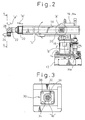
- Figure 2 illustrates, by way of example, a robot unit provided for a laser robot to which a beam axis adjusting method in accordance with the present invention is applied.
- the robot unit 10 of the laser robot is provided with a base 12, and movable robot components including a rotary table 14 mounted on the base 12, a robot body 16 set upright for ⁇ -axis turning in directions indicated by the arrows about a vertical axis on the rotary table 14, an elongated first robot arm 18 pivotally joined for U-axis turning in a vertical plane in directions indicated by the arrows to the upper portion of the robot body 16, a second robot arm 20 projecting from the front end of the first robot arm 18 and supported for R-axis axial movement in directions indicated by the arrows, and a robot wrist 22 joined to the extremity of the second robot arm 20 for ⁇ -axis turning in directions indicated by the arrows.
- a rotary table 14 mounted on the base 12
- a robot body 16 set upright for ⁇ -axis turning in directions indicated by the arrows about a vertical axis on the rotary table 14
- an elongated first robot arm 18 pivotally joined for U-axis turning in a
- the robot body 16 is driven for turning by a driving motor M ⁇ mounted on the base 12 through a transmission mechanism, such as a belt-and-pulley mechanism built into the base 12.
- the first robot arm 18 is driven for turning by a driving motor Mu mounted on the robot body 16 through a transmission mechanism, such as a ball-and-screw mechanism.
- the second robot arm 20 is driven for axial movement and the robot wrist is driven for turning respectively by driving motors Mr and M ⁇ mounted on the rear portion of the first robot arm 18.
- Joint structures are formed respectively in the pivotal joint of the robot body 16 and the first robot arm 18, and in a portion of the robot wrist for an ⁇ - axis motion.
- a laser beam projecting unit 24 internally provided with a laser beam focusing means is attached to the extremity of the robot wrist 22.
- a laser beam emitted by a laser generator is ducted through a laser beam conduit, not shown, so as to fall on the robot unit of the laser robot thus constructed from above or from below the same.
- the laser beam is introduced into the robot unit 10 through a laser beam inlet formed in the upper end of the robot body 16.
- the laser beam introduced into the robot unit 10 is deflected by a reflecting mirror unit disposed on the axis of the joint structure joining together the robot body 16 and the first robot arm 18, i.e., on the axis of the U-axis turning of the first robot arm 18 so as to travel through the first robot arm 18, the laser beam traveling through the first robot arm is deflected again by another reflecting mirror unit disposed within the first robot arm 18 so as to travel through a laser beam conduit extending through the first robot arm 18 and the second robot arm 20 toward the robot wrist 22.
- the laser beam is deflected by a reflecting mirror unit 28 incorporated into the robot wrist 22 toward a focusing means such as a parabolic mirror, and then a laser beam projecting unit 24 projects the laser beam on a workpiece.
- the laser beam pathway along which the laser beam travels coincides with the respective axes of the ⁇ -axis turning of the robot body 16, the U-axis turning of the first robot arm 18 and the ⁇ -axis turning of the robot wrist 22.
- the laser beam pathway is adjusted when manufacturing the laser robot, before shipping the laser robot, when installing the laser robot in an operating site, after resetting the laser beam and when inspecting the laser robot for maintenance.
- the present invention employs a beam axis adjusting device 30 including a semitransparent target plate, such as a translucent glass plate, for beam axis adjustment in combination with a laser beam splitter, not shown in Fig. 2, i.e., a beam splitter comprising a half-mirror to enable the operator to simply perform the beam axis adjustment.
- a semitransparent target plate such as a translucent glass plate
- a method of adjusting the beam axis of a laser robot which disposes the beam axis adjusting device 30 at a single position in the laser beam pathway in the robot unit, detects the misalignment of the beam axis with an axis of motion and adjusts the reflecting mirror unit so that the beam axis coincides with the axis of motion, is unable to detect a minute inclination of the beam axis relative to the axis of motion. Therefore, two beam axis adjusting devices 30 are disposed at two separate and spaced positions and the reflecting mirror units are adjusted for beam axis adjustment so that the beam axis coincides with the axes of motion at the two positions.
- the two beam axis adjusting devices 30 are detachably attached to the robot unit respectively at a suitable position in the rear portion of the first robot arm 18 (a position indicated at " A ") and a position at the extremity of the robot wrist 22 to carry out the beam axis adjustment.
- the laser beam projecting unit 24 is detached temporarily from the robot wrist 22, and in turn the beam axis adjusting device 30 is attached to the robot wrist 22 instead of the laser beam projecting unit 24.
- Figure 3 illustrates the beam axis adjusting device 30 mounted on the first robot arm 18 in an enlarged view
- Fig. 4 illustrates the beam axis adjusting device 30 attached to the extremity of the robot wrist 22.
- These two beam axis adjusting devices 30 are identical in construction and differ from each other in the size thereof.
- Figure 5 is a sectional view, taken along the line 5-5 in Fig. 4.
- the beam axis adjusting device 30 is provided with, as principal components, a semitransparent member, for example, a target plate 32 made of a translucent glass plate, and a frame 34 holding the target plate 32.
- the target plate 32 is provided with a plurality of concentric scale circles 36 depicted thereon.
- the frame 34 is made of a light metallic material, such as an aluminum material.
- Mounting holes 38 are formed in the peripheral area of the frame 34. Screws are inserted in the mounting holes 38 and screwed into the robot body to fasten the frame 34 to the robot body.
- the target plate 32 is semitransparent, a light spot formed on one surface thereof can be visually recognized from behind the outer surface of the target plate 32. The operator observes the light spot visually to detect the misalignment of the beam axis with the axis of motion during beam axis adjustment.
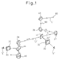
- a laser beam L is deflected by a reflecting mirror unit 40 arranged within a laser beam conduit extended outside the robot unit 10 so as to travel through the laser beam inlet 50 formed in the robot unit 10 (robot body 16) into the robot unit 10. Subsequently, the laser beam L is deflected by a reflecting mirror unit 26 disposed on the axis of turning of the first robot arm 18 at the joint pivotally joining together the robot body 16 and the first robot arm 18 so as to travel through the first robot arm 18 and the second robot arm 20. The laser beam L is then deflected by a reflecting mirror unit 28 disposed within the robot wrist 22 toward the focusing mirror 46, and further the laser beam L is projected on an object to be irradiated with the laser beam.
- a visible laser beam L emitted by a laser generator 60 is guided into the robot body, and half mirrors 42 and 46 serving as beam splitters are disposed respectively at two spaced-apart positions.
- the beam axis adjusting devices 30 each provided with the target plate 32 are detachably attached to the outer surface of the robot body at respective positions corresponding to the half mirrors 42 and 44.
- the half mirror 42 (44) splits the visible laser beam L into a first laser beam L1 that penetrates the half mirror 42 (44) and travels straight and a second laser beam L2 deflected by the half mirror 42 (44).
- the second laser beam L2 falls on the target plate 32 of the beam axis adjusting device 30 in a light spot as indicated by a broken line Sp on the target plate 32 in Figs. 3 and 4.
- the light spot Sp formed by the visible laser beam on the irradiated front surface of the target plate 32 of the beam axis adjusting device 30 can be visually recognized by the operator E from behind the back surface of the target plate 32.
- the light spot Sp is produced on the front surface of the target plate 32, and then the operator E turns the first robot arm 18 about the U-axis, while observing the light spot Sp.
- the center axis of the visual laser beam is aligned with the axis of turning of the first robot arm 18, the light spot Sp remains stationary with its center in coincidence with the center of the target plate 32.
- the center axis of the visible laser beam is misaligned with the axis of turning of the first robot arm 18, the light spot Sp moves along a circular locus on the target plate 32 as the first robot arm 18 is turned about the axis of turning.
- the reflecting mirror units 26 and 27 are adjusted so that the light spot Sp contracts into a point-like spot on the target plate 32 even if the first robot arm 18 is turned about the axis of turning thereof.
- the beam axis adjusting device 30 on the first robot arm 18 is first used for the adjustment of the beam axis. Subsequently, the beam axis adjusting devices 30 on the robot wrist 22 is used for further fine adjustment of the beam axis by adjusting the reflecting mirror unit 28 arranged at the robot wrist 22.
- the reflecting mirror unit 28 is repeatedly adjusted to bring the beam axis into alignment with the axis of turning of the robot wrist 22.
- the beam axis adjustment is completed when both the light spots Sp produced respectively on the target plates 32 of both the beam axis adjusting devices 30 become stationary with their center at the center of the corresponding target plates 32.
- the concentric scale circles 36 formed on the target plates 32 facilitate the visual recognition of degree of adjustment of the light spots Sp.
- the beam axis adjusting method for a laser robot can be easily carried out by using a visible laser beam in the stage of manufacture of the laser robot, in the stage of shipping the laser robot, in the stage of installing the laser robot in an operating site and when moving the laser robot from one operating site to another.
- the beam axis of the robot unit can be aligned with axes of turning of the laser robot simply by adjusting the beam axis of the robot unit by using the beam axis adjusting devices 30 provided with the target plate 32, respectively, before moving the robot unit from the first operating site, projecting a laser beam on the target plates 32 of the beam axis adjusting devices 30 to form light spots respectively on the target plates 32 after installing the robot unit in the second operating site, and adjusting the connection of the external laser beam conduit and the robot unit 10 so that the light spots are concentric with the scale circles of the target plates 32. Accordingly, the troublesome beam axis adjusting operation can be omitted.
- a beam axis adjusting operation can be achieved, without requiring the adjustment of the reflecting mirror unit 26 and the other reflecting mirror units, by installing the laser robot in an operating site, connecting the external laser beam conduit to the robot unit and adjusting the connection of the external laser beam conduit and the robot unit so that a laser beam ducted through the external laser beam conduit into the robot unit forms light spots concentric with the scale circles 36 on the target plates 32 of the beam axis adjusting devices 30.
- the beam axis of the laser robot along which a laser beam travels can be aligned with the axes of motion of the joints of a laser robot simply by using the simple beam axis adjusting devices provided with the target plates having semitransparent members. Furthermore, since the degree of adjustment of the beam axis can be recognized through the visual observation of the light spot produced on the target plate from behind the back surface of the target plate, the beam axis adjusting operation can be simplified.
- the beam axis adjustment can be achieved after installing the laser robot in an operating site simply by connecting an external laser beam conduit to the robot unit, forming light spots on the target plates of the beam axis adjusting devices and adjusting the connection of the external laser beam conduit and the robot unit so that the light spots are formed at the same positions as those at which light spots were formed when the beam axis was adjusted correctly before the shipment of the laser robot:
- the installation of the laser robot in the operating site such as a workshop, can be quickly completed.
- the beam axis of the laser robot when the beam axis of the laser robot is adjusted correctly before moving the laser robot from a first operating site to a second operating site, the beam axis can be correctly adjusted without repeating troublesome beam axis adjusting operation after installing the laser robot in the second operating site.
Landscapes
- Physics & Mathematics (AREA)
- Optics & Photonics (AREA)
- Engineering & Computer Science (AREA)
- Plasma & Fusion (AREA)
- Mechanical Engineering (AREA)
- Laser Beam Processing (AREA)
- Manipulator (AREA)
- Length Measuring Devices By Optical Means (AREA)
Abstract
L'invention concerne un procédé de réglage de l'axe optique d'un robot laser. Un faisceau laser est divisé en deux par un séparateur de faisceau placé sur sa trajectoire dans le robot, et une composante du faisceau est introduite dans la partie superficielle d'une plaquette cible translucide fixée au corps du robot laser, pour former un point (Sp). L'on régle la position de chaque mirroir réflecteur, à l'intérieur du corps du robot, tout en observant ledit point (Sp) depuis l'arrière de la plaquette cible lorsque chaque élément de liaison du robot laser est actionné de façon à ajuster l'axe optique.
Applications Claiming Priority (2)
| Application Number | Priority Date | Filing Date | Title |
|---|---|---|---|
| JP4016375A JPH05209731A (ja) | 1992-01-31 | 1992-01-31 | レーザロボットの光軸調整方法 |
| JP16375/92 | 1992-01-31 |
Publications (2)
| Publication Number | Publication Date |
|---|---|
| EP0585463A1 true EP0585463A1 (fr) | 1994-03-09 |
| EP0585463A4 EP0585463A4 (en) | 1994-07-06 |
Family
ID=11914551
Family Applications (1)
| Application Number | Title | Priority Date | Filing Date |
|---|---|---|---|
| EP19930902537 Withdrawn EP0585463A4 (en) | 1992-01-31 | 1993-01-27 | Method of adjusting optical axis for laser robot |
Country Status (4)
| Country | Link |
|---|---|
| US (1) | US5484982A (fr) |
| EP (1) | EP0585463A4 (fr) |
| JP (1) | JPH05209731A (fr) |
| WO (1) | WO1993014899A1 (fr) |
Families Citing this family (14)
| Publication number | Priority date | Publication date | Assignee | Title |
|---|---|---|---|---|
| JP3229834B2 (ja) * | 1997-04-07 | 2001-11-19 | 本田技研工業株式会社 | 溶接方法およびその装置 |
| US7245412B2 (en) * | 2001-02-16 | 2007-07-17 | Electro Scientific Industries, Inc. | On-the-fly laser beam path error correction for specimen target location processing |
| US8497450B2 (en) | 2001-02-16 | 2013-07-30 | Electro Scientific Industries, Inc. | On-the fly laser beam path dithering for enhancing throughput |
| JP4340745B2 (ja) * | 2002-01-11 | 2009-10-07 | エレクトロ サイエンティフィック インダストリーズ インコーポレーテッド | レーザースポットを拡大するワークピースのレーザー加工方法 |
| US6706998B2 (en) | 2002-01-11 | 2004-03-16 | Electro Scientific Industries, Inc. | Simulated laser spot enlargement |
| DE10261592B3 (de) * | 2002-12-24 | 2004-10-28 | Reis Gmbh & Co. Maschinenfabrik | Knickarmroboter |
| US6706999B1 (en) | 2003-02-24 | 2004-03-16 | Electro Scientific Industries, Inc. | Laser beam tertiary positioner apparatus and method |
| US7218649B2 (en) * | 2003-08-28 | 2007-05-15 | Philip Morris Usa Inc. | Laser beam containment system |
| US20060213884A1 (en) * | 2005-03-23 | 2006-09-28 | Button International Co., Ltd. | Multi-angular laser processing apparatus |
| US9371957B2 (en) * | 2005-12-21 | 2016-06-21 | Reliant Technologies, Llc | Articulated arm for delivering a laser beam |
| JP4621725B2 (ja) * | 2007-12-25 | 2011-01-26 | 株式会社東芝 | 光伝送装置およびその調整方法 |
| CN103100797B (zh) * | 2013-01-23 | 2015-09-09 | 刘茂珍 | 基于自适应光学的激光微细加工设备和方法 |
| EP3183093B1 (fr) | 2015-06-22 | 2020-08-05 | Electro Scientific Industries, Inc. | Machine-outil à axes multiples et ses procédés de commande |
| KR102202898B1 (ko) * | 2018-04-27 | 2021-01-15 | (주)엔피에스 | 레이저 장치 |
Family Cites Families (7)
| Publication number | Priority date | Publication date | Assignee | Title |
|---|---|---|---|---|
| IL48554A (en) * | 1975-11-27 | 1978-07-31 | Laser Ind Ltd | Laser beam aligning apparatus |
| US4468119A (en) * | 1982-05-24 | 1984-08-28 | Hamar M R | Penta-prism module having laser alignment error detection and correction capability |
| US4566202A (en) * | 1983-12-06 | 1986-01-28 | Hamar M R | Laser apparatus for effectively projecting the axis of rotation of a rotating tool holder |
| DE3406677A1 (de) * | 1984-02-24 | 1985-09-05 | Fa. Carl Zeiss, 7920 Heidenheim | Einrichtung zur kompensation der auswanderung eines laserstrahls |
| US4840483A (en) * | 1987-12-18 | 1989-06-20 | Cincinnati Milacron Inc. | Alignment tool for laser beam delivery systems and method of alignment |
| JPH0338611A (ja) * | 1989-07-05 | 1991-02-19 | Think Lab Kk | ガスレーザーのビームの通りを修正する方法 |
| JPH03106586A (ja) * | 1989-09-20 | 1991-05-07 | Fanuc Ltd | 多関節レーザロボット用アライメント装置及びその調整方法 |
-
1992
- 1992-01-31 JP JP4016375A patent/JPH05209731A/ja active Pending
-
1993
- 1993-01-27 WO PCT/JP1993/000097 patent/WO1993014899A1/fr not_active Ceased
- 1993-01-27 EP EP19930902537 patent/EP0585463A4/en not_active Withdrawn
- 1993-01-27 US US08/119,162 patent/US5484982A/en not_active Expired - Fee Related
Also Published As
| Publication number | Publication date |
|---|---|
| JPH05209731A (ja) | 1993-08-20 |
| EP0585463A4 (en) | 1994-07-06 |
| US5484982A (en) | 1996-01-16 |
| WO1993014899A1 (fr) | 1993-08-05 |
Similar Documents
| Publication | Publication Date | Title |
|---|---|---|
| US5484982A (en) | Beam axis adjusting method for a laser robot | |
| US5925268A (en) | Laser welding apparatus employing a tilting mechanism and seam follower | |
| JP7755243B2 (ja) | レーザ指向変化時に経路偏差を補正する方法及びその装置並びに工作機械 | |
| CN100488698C (zh) | 激光焊接系统和激光焊接控制方法 | |
| EP1769878A1 (fr) | Métode et système pour afficher le statut d'irradiation du laser avec une tête de balayage | |
| CN100595017C (zh) | 激光束三级定位器装置和方法 | |
| JPS59134682A (ja) | マニピュレ−タ装置 | |
| CN217370913U (zh) | 激光指向改变时校正路径偏离的装置和机床 | |
| US4825034A (en) | Microbeam laser machine for acting on objects having thin layers of material | |
| JPH10249566A (ja) | レーザ加工方法および装置 | |
| JP7569978B2 (ja) | 超短パルスレーザー回転方向誤差を補償する方法及びその装置並びに工作機械 | |
| CN112264723A (zh) | 适用于小型复杂曲面零件的激光微孔加工设备及加工方法 | |
| CN114101898A (zh) | 一种激光加工装置 | |
| US5233202A (en) | Method of adjusting an optical path followed by a laser beam in a laser robot and an apparatus for carrying out the same | |
| JPS62144875A (ja) | エレクトロニクス構成要素を回路基板にはんだづけする装置 | |
| CN120587674A (zh) | 氢能源电池模组激光焊接设备 | |
| JPH0782154B2 (ja) | レーザービーム等の平行ビームを配送するための装置 | |
| JP3511049B2 (ja) | レ−ザ加工装置 | |
| CN220515747U (zh) | 一种多点激光打标辅助对焦装置 | |
| JP5741417B2 (ja) | レーザー加工ロボットシステム | |
| JP3010769B2 (ja) | 光素子モジュールの組立方法および装置 | |
| JP3116481B2 (ja) | 光素子モジュールの組立装置 | |
| JPH01148486A (ja) | レーザ加工ロボット | |
| CN223805126U (zh) | 一种用于激光冲击强化的高自由度硬光路传输装置 | |
| JP3148011B2 (ja) | レーザ加工装置 |
Legal Events
| Date | Code | Title | Description |
|---|---|---|---|
| PUAI | Public reference made under article 153(3) epc to a published international application that has entered the european phase |
Free format text: ORIGINAL CODE: 0009012 |
|
| 17P | Request for examination filed |
Effective date: 19930922 |
|
| AK | Designated contracting states |
Kind code of ref document: A1 Designated state(s): DE IT SE |
|
| A4 | Supplementary search report drawn up and despatched | ||
| AK | Designated contracting states |
Kind code of ref document: A4 Designated state(s): DE IT SE |
|
| 17Q | First examination report despatched |
Effective date: 19951019 |
|
| STAA | Information on the status of an ep patent application or granted ep patent |
Free format text: STATUS: THE APPLICATION HAS BEEN WITHDRAWN |
|
| 18W | Application withdrawn |
Withdrawal date: 19960209 |