EP0587567B2 - Spritzenpumpe mit Frontladung - Google Patents
Spritzenpumpe mit Frontladung Download PDFInfo
- Publication number
- EP0587567B2 EP0587567B2 EP92905378A EP92905378A EP0587567B2 EP 0587567 B2 EP0587567 B2 EP 0587567B2 EP 92905378 A EP92905378 A EP 92905378A EP 92905378 A EP92905378 A EP 92905378A EP 0587567 B2 EP0587567 B2 EP 0587567B2
- Authority
- EP
- European Patent Office
- Prior art keywords
- syringe
- jacket
- injector
- tube
- plunger
- Prior art date
- Legal status (The legal status is an assumption and is not a legal conclusion. Google has not performed a legal analysis and makes no representation as to the accuracy of the status listed.)
- Expired - Lifetime
Links
- 230000033001 locomotion Effects 0.000 claims abstract description 60
- 239000012530 fluid Substances 0.000 claims abstract description 38
- 238000000034 method Methods 0.000 claims abstract description 24
- 230000008878 coupling Effects 0.000 claims description 73
- 238000010168 coupling process Methods 0.000 claims description 73
- 238000005859 coupling reaction Methods 0.000 claims description 73
- 239000007788 liquid Substances 0.000 claims description 38
- 238000002347 injection Methods 0.000 claims description 17
- 239000007924 injection Substances 0.000 claims description 17
- 230000000452 restraining effect Effects 0.000 claims description 12
- 230000013011 mating Effects 0.000 claims description 11
- 238000003780 insertion Methods 0.000 claims description 5
- 230000037431 insertion Effects 0.000 claims description 5
- 230000001419 dependent effect Effects 0.000 claims 5
- 230000002093 peripheral effect Effects 0.000 claims 2
- 230000007246 mechanism Effects 0.000 description 23
- 239000003708 ampul Substances 0.000 description 5
- 239000000463 material Substances 0.000 description 5
- 239000004033 plastic Substances 0.000 description 3
- 239000012780 transparent material Substances 0.000 description 3
- 230000036512 infertility Effects 0.000 description 2
- 230000000717 retained effect Effects 0.000 description 2
- 238000004140 cleaning Methods 0.000 description 1
- 230000003749 cleanliness Effects 0.000 description 1
- 238000002591 computed tomography Methods 0.000 description 1
- 239000013536 elastomeric material Substances 0.000 description 1
- 230000002708 enhancing effect Effects 0.000 description 1
- 230000014759 maintenance of location Effects 0.000 description 1
- 239000002991 molded plastic Substances 0.000 description 1
- 239000000843 powder Substances 0.000 description 1
- 230000003014 reinforcing effect Effects 0.000 description 1
- 239000012858 resilient material Substances 0.000 description 1
- 238000007789 sealing Methods 0.000 description 1
Images




Classifications
-
- A—HUMAN NECESSITIES
- A61—MEDICAL OR VETERINARY SCIENCE; HYGIENE
- A61M—DEVICES FOR INTRODUCING MEDIA INTO, OR ONTO, THE BODY; DEVICES FOR TRANSDUCING BODY MEDIA OR FOR TAKING MEDIA FROM THE BODY; DEVICES FOR PRODUCING OR ENDING SLEEP OR STUPOR
- A61M5/00—Devices for bringing media into the body in a subcutaneous, intra-vascular or intramuscular way; Accessories therefor, e.g. filling or cleaning devices, arm-rests
- A61M5/14—Infusion devices, e.g. infusing by gravity; Blood infusion; Accessories therefor
- A61M5/142—Pressure infusion, e.g. using pumps
- A61M5/145—Pressure infusion, e.g. using pumps using pressurised reservoirs, e.g. pressurised by means of pistons
- A61M5/1452—Pressure infusion, e.g. using pumps using pressurised reservoirs, e.g. pressurised by means of pistons pressurised by means of pistons
- A61M5/14546—Front-loading type injectors
-
- A—HUMAN NECESSITIES
- A61—MEDICAL OR VETERINARY SCIENCE; HYGIENE
- A61M—DEVICES FOR INTRODUCING MEDIA INTO, OR ONTO, THE BODY; DEVICES FOR TRANSDUCING BODY MEDIA OR FOR TAKING MEDIA FROM THE BODY; DEVICES FOR PRODUCING OR ENDING SLEEP OR STUPOR
- A61M2250/00—Specially adapted for animals
-
- A—HUMAN NECESSITIES
- A61—MEDICAL OR VETERINARY SCIENCE; HYGIENE
- A61M—DEVICES FOR INTRODUCING MEDIA INTO, OR ONTO, THE BODY; DEVICES FOR TRANSDUCING BODY MEDIA OR FOR TAKING MEDIA FROM THE BODY; DEVICES FOR PRODUCING OR ENDING SLEEP OR STUPOR
- A61M5/00—Devices for bringing media into the body in a subcutaneous, intra-vascular or intramuscular way; Accessories therefor, e.g. filling or cleaning devices, arm-rests
- A61M5/14—Infusion devices, e.g. infusing by gravity; Blood infusion; Accessories therefor
- A61M5/142—Pressure infusion, e.g. using pumps
- A61M5/145—Pressure infusion, e.g. using pumps using pressurised reservoirs, e.g. pressurised by means of pistons
- A61M5/1452—Pressure infusion, e.g. using pumps using pressurised reservoirs, e.g. pressurised by means of pistons pressurised by means of pistons
- A61M5/14566—Pressure infusion, e.g. using pumps using pressurised reservoirs, e.g. pressurised by means of pistons pressurised by means of pistons with a replaceable reservoir for receiving a piston rod of the pump
-
- A—HUMAN NECESSITIES
- A61—MEDICAL OR VETERINARY SCIENCE; HYGIENE
- A61M—DEVICES FOR INTRODUCING MEDIA INTO, OR ONTO, THE BODY; DEVICES FOR TRANSDUCING BODY MEDIA OR FOR TAKING MEDIA FROM THE BODY; DEVICES FOR PRODUCING OR ENDING SLEEP OR STUPOR
- A61M5/00—Devices for bringing media into the body in a subcutaneous, intra-vascular or intramuscular way; Accessories therefor, e.g. filling or cleaning devices, arm-rests
- A61M5/14—Infusion devices, e.g. infusing by gravity; Blood infusion; Accessories therefor
- A61M5/142—Pressure infusion, e.g. using pumps
- A61M5/145—Pressure infusion, e.g. using pumps using pressurised reservoirs, e.g. pressurised by means of pistons
- A61M5/1452—Pressure infusion, e.g. using pumps using pressurised reservoirs, e.g. pressurised by means of pistons pressurised by means of pistons
- A61M5/1458—Means for capture of the plunger flange
-
- Y—GENERAL TAGGING OF NEW TECHNOLOGICAL DEVELOPMENTS; GENERAL TAGGING OF CROSS-SECTIONAL TECHNOLOGIES SPANNING OVER SEVERAL SECTIONS OF THE IPC; TECHNICAL SUBJECTS COVERED BY FORMER USPC CROSS-REFERENCE ART COLLECTIONS [XRACs] AND DIGESTS
- Y10—TECHNICAL SUBJECTS COVERED BY FORMER USPC
- Y10S—TECHNICAL SUBJECTS COVERED BY FORMER USPC CROSS-REFERENCE ART COLLECTIONS [XRACs] AND DIGESTS
- Y10S128/00—Surgery
- Y10S128/01—Motorized syringe
Definitions
- the present invention relates to injectors and more particularly to disposable replacement syringes for animal fluid injectors.
- Injectors are devices that expel fluid, such as contrasting media, from a syringe and through a tube into an animal.
- the injectors are provided with an injector unit, usually adjustably fixed to a stand or support, having a drive that couples to the plunger of the syringe to drive it forward to expel fluid into the tube, or that may be driven rearward to draw fluid into the syringe to fill it.
- the syringe is a disposable replacement type.
- pressures are developed in the syringe that range from, for example, twenty-five psi for some applications to over 6.85 to 8.22 MN/m 2 (1000 to 1200 psi) for other applications.
- Syringes that will contain fluid under such pressures are expensive and therefore impractical where the syringes are to be disposable.
- many such injectors such as angiographic injectors, for example, have been provided with pressure jackets fixed to the injector units and into which the syringes are inserted. The pressure jackets contact the outer surfaces of the syringe to restrain the walls of the syringe against the internal pressures.
- the jackets of the prior art have been configured to surround the front ends of the syringes to restrain the syringe front wall against forward acting forces of the drive and the fluid pressure and to hold the syringe in the jacket. Because the front end of the pressure jacket is closed, rear loading was necessary, and accessibility thereto was provided by hinging or rotating the jacket to allow for removal and replacement of the syringe from the rear.
- the opening and reclosing of the injector unit to replace the syringe requires a certain amount of time, which, in the course of the procedure being performed, is not wholly desirable.
- injector units of various types have been capable of disconnection of the plunger drive from the drive coupling on the syringe plunger at any position of the plunger within the syringe, retraction of the drive is typically required before the syringe can be removed. This is because the opening of the injector unit to remove and insert the syringe from the rear requires, for example, a translating or rotating of the jacket from the axis of the drive, which cannot be achieved if the plunger drive is extended.
- the syringe plunger typically is forward, as is the plunger drive. Since, in the prior art injectors that load from the rear, the pressure jacket is moved through the position that the drive occupies when extended in order to remove the syringe. Hence, the syringe cannot be immediately removed without retracting the plunger drive. Further, the disposable tubing that connects to the nozzle of the syringe must be disconnected from the syringe in order to remove the syringe from the jacket. Additionally, when an empty new syringe is inserted, the drive must be in its retracted position.
- the syringe is inserted empty and filled by retraction of the plunger with an injection tube connected to a supply of the fluid that is to be injected.
- the plunger be fully forward in the syringe so that the syringe can be filled by rearward retraction of the plunger.
- it is then necessary to fully advance the drive to the position in which it in engagement with the plunger and the plunger is in its full forward position. The drive then engages a coupling on the plunger of the replacement syringe. This need to retract and advance the drive contributes to a loss of time in the syringe replacement process.
- US Patent 4150672 describes an injection apparatus in which a disposable ampule is inserted rearwardly into a tubular ampule support mounted within a powder unit. A cap assembly is locked to the support to hold the ampule in place and includes a needle for piercing a front wall of the ampule and accessing liquid therein.
- the ampule includes a slidable piston which is engaged and pushed forwards by an expelling device in the power unit.
- An additional objective of the present invention is to provide an injector and replaceable syringe therefor that will facilitate control of the orientation of the syringe in the jacket, and thereby provide for positive, rapid and reliable engagement of the syringe with locking structure that holds the syringe in the jacket, engagement of the plunger drive and plunger drive coupling, or connection of the injection tube to the outlet of the syringe.
- a further objective of the present invention is to provide for easy to operate mechanism and reliable locking structure for locking the syringe in place in the pressure jacket of the injection unit.
- Another objective of the present invention is to provide an injector and syringe arrangement that minimizes or eliminates the probability of spillage from the syringe nozzle flowing into the injector equipment, and otherwise enhancing the ability to maintain sterility and cleanliness 10 of the equipment.
- a disposable replacement liquid container for a front loadable injector as defined in claim 1.
- a disposable replacement liquid container for a front loadable injector as defined in claim 53.
- a front loadable injector as defined in claim 21.
- an angiographic injector having a front end loadable syringe that can be loaded into and removed from the injector pressure jacket through an opening that is provided in the front end of the pressure jacket.
- the syringes of the present invention are provided with a front wall that is pressure restraining, that is, is of sufficient strength to support the front of the syringe against the expected pressures within the syringe, and that is securable to the front end of the pressure jacket so as to complete the pressure restraining enclosure of the syringe within the pressure jacket and hold the syringe in the jacket.
- this front end of the injector is formed of a separate pressure restraining cap made of material that is separate from the front wall of the syringe and may be reusable.
- the cap may be formed integrally of the front syringe wall.
- the front end of the syringe -locks to the front end of the pressure jacket through a cooperating engagement of mating threads on the syringe jacket.
- the threads include external thread sections formed at the front end of the pressure jacket and internal threads formed on an outwardly extending flange or rim of the front wall of the syringe, preferable on a pressure restraining cap.
- other securing or locking structure such as a clip or an adaptor, for example, may be employed to join the syringe to the jacket.
- the threads are engageable in a limited number of angular positions to thereby predetermine the angular orientation of the syringe in the pressure jacket.
- other keys and keyways carried respectively by the unit and by the syringe limit the angular position in which the syringe may be inserted into the jacket to a unique predetermined angular orientation.
- a coupling on the syringe plunger is centrally located and symmetrical about the axis of the plunger.
- a pair of jaws on the plunger drive is moveable either by transverse straight or arcuate translatory motion or by forward longitudinal motion to form a connection between the coupling and the drive. Once coupled to the drive, the coupling remains engaged to the drive during longitudinal motion of the drive to cause the plunger to move forward or backward with the drive.
- Disengagement occurs thereafter only upon transverse translational motion of the plunger with respect to the drive.
- this translatory transverse motion occurs by translatory movement of the jacket, and the injector unit door that carries the jacket, with respect to the plunger drive and the unit housing.
- an asymmetrical coupling is provided that engages and disengages the plunger drive upon rotational movement of the syringe with respect to the drive.
- the motion for locking the syringe to, and unlocking the syringe from, the jacket is achieved by rotation of the syringe in the jacket, and preferably, this motion is linked to, and occurs simultaneous with, the motion that engages and disengages the plunger coupling and drive, whether that coupling is by translation or rotation.
- the syringe and plunger drive are so dimensioned and positioned to prevent contact between the drive and the sterile interior wall of the syringe, regardless of the position of the drive, as the syringe is being loaded.
- the syringe is formed of a cylindrical body, with the front end in the shape of a truncated cone that terminates in a forwardly extending neck with an orifice at its remote end that is connectable with an injection tube.
- the front end of the syringe is shaped so as to direct fluid leaking from the nozzle outwardly around the front end of the jacket. This prevents leakage, which often results upon disconnection of the injection tubing, from entering the space between the pressure jacket and the syringe body.
- Replacement of the syringe begins, in the preferred embodiments of the invention, with the unlocking the syringe at its front end from the front end of the pressure jacket, preferably by rotating the syringe with respect to the jacket, and by disengaging the plunger drive from the syringe plunger, alternatively by transverse translational or rotational motion, preferably simultaneous with and linked to the motion that disengages the syringe from the jacket.
- the unlocking of the syringe from the jacket occurs, for example, by loosening mating threads at the front of the syringe and jacket.
- the twisting of the syringe in the jacket is linked to motion that either translates transversely or rotates a coupling on the syringe plunger out of engagement with the plunger drive.
- the syringe is removed from the jacket through the open front end of the jacket. This removal may take place without retraction of the plunger drive, should the drive be advanced in the pressure jacket at the time of disengagement from the plunger coupling.
- the used syringe may also be removed without disconnection of the disposable injection tubing from the nozzle of the syringe.
- a replacement syringe is inserted into the jacket through its open forward end and the front end of the new syringe is locked to the front end of the jacket, preferably by relative rotation of the syringe in the jacket to cause, for example, engagement between mating threads on the front end of the syringe and the front end of the jacket.
- the plunger drive in one embodiment, is translated to bring the plunger coupling engaging jaws into alignment with the plunger coupling, preferably simultaneously with the locking of the syringe to the jacket.
- the jaws thereby either engage the coupling upon the translatory motion, or thereafter engage the coupling by longitudinal advancement of the drive against the coupling.
- the jaws are positioned off center of the drive so that the drive, whether in the engaging or the disengaging positions, does not contact a syringe as the syringe is guided by the jacket during loading.
- engagement of the plunger drive with the coupling occurs by relative rotation of the drive and the coupling, preferably by rotating the coupling relative to a stationary plunger drive, rather than by translational motion between the drive and the coupling. Only if the rest position of the plunger of the replacement syringe is behind the final position of the plunger drive at the time it was disconnected from the coupling of the plunger of the syringe being replaced need the plunger drive be retracted.
- the engagement and disengagement motions between the plunger drive and plunger drive coupling, and between the syringe and the pressure jacket are provided with manually operable mechanism that, in the preferred and illustrated embodiments, rotates the syringe in the jacket and further either rotates or translates the coupling with respect to the plunger drive, with a simple one hand operated mechanism.
- the mechanism provides a convenient lever, operable through a short arc, to rotate the syringe in the jacket and to then, preferably, translate the pressure jacket that carries the syringe and is carried by the injector unit door, or to otherwise move the syringe with respect to the drive, to bring the plunger coupling of the syringe into or out of alignment with the plunger drive.
- the present invention provides a disposable syringe that may be replaced in an angiographic or CT injector with great efficiency and speed. Further, replacement may occur without retraction of the plunger drive of the injector unit. Simple and rapid one hand operation of the engaging and disengaging structure is provided.
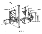
- Fig. 1 is a perspective view of an angiographic CT injector embodying principles of the present invention.
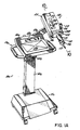
- Fig. 1A is a perspective view of an another form of angiographic injector embodying principles of the present invention.
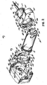
- Fig. 2 is an exploded perspective view of a portion of one preferred embodiment of the injector of Fig. 1 .
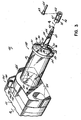
- Fig. 3 is a perspective view of the portion of the injector of Fig. 2 .
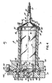
- Fig. 4 is a cross-sectional view along lines 4-4 of Fig. 3 illustrating a replaceable syringe unlocked from the housing for insertion into or removal therefrom.
- Fig. 5 is a cross-sectional view similar to Fig. 4 but illustrating the syringe locked to the structure carried by the housing.
- Fig. 6 is a cross-sectional view along the line 6-6 of Fig. 5 .
- Fig. 7 is an elevational diagrammatic illustration of the injector of Fig. 1 with the pressure jacket and syringe removed, and showing the syringe locking structure in the locked position such as in Figs. 5 and 6 .
- Fig. 8 is an elevational diagrammatic view similar to Fig. 7 illustrating the syringe locking structure in the unlocked position such as in Figs. 2-4 .
- Fig. 9 is an elevational diagrammatic view similar to Fig. 7 illustrating the locking mechanism in the housing door release position.
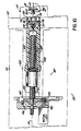
- Fig. 10 is a cross-sectional view through the housing of the injector taken along lines 10-10 of Fig. 1 with the plunger drive disengaged from the syringe plunger coupling.
- Fig. 11 is a view of a portion of Fig. 10 illustrating the plunger drive longitudinally moving into engagement with the plunger coupling.
- Fig. 12 is a view of a portion of Fig. 10 illustrating the plunger drive in engagement with the plunger coupling.
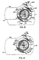
- Fig. 13 is a front view of a portion of another embodiment of the injector of Fig. 1 .
- Fig. 14 is a view of an alternative embodiment of a portion of a syringe according to principles of the present invention.
- Fig. 15 is a cross-sectional view similar to Fig. 5 of an alternative embodiment of the invention, illustrating alternative engaging structure between the front ends of the syringe and jacket.
- Fig. 16 is a front end view of still a further alternative embodiment of the invention, also illustrating alternative engaging structure between the front ends of the syringe and jacket.
- an angiographic injector 10 configured for CT applications.
- the injector 10 includes a ceiling mounted support 11, adjacent a CT X-ray unit, to the lower surface of which is rigidly supported a vertically descending support column 12.
- an injector control module console 13 Remote from the support 11 is an injector control module console 13 behind a wall which isolates the operator area from the X-ray equipment.
- the console 13 is located adjacent a control 14 of the X-ray equipment. Electrical power and control cables (not shown) communicate power and control signals through the support 11 and the column 12 and to a power lead 15.
- the console 13 connects with an injector control module 16, which includes a programmable microprocessor (not shown) to which commands and programming codes are input through a keyboard 17 on the console 13.
- the console 13 is also provided with an operator display 18 to aid in interfacing the input commands and injector status with the operator.
- Attached to the column 12 is an articulating adjustable arm 19.
- To the remote end of the arm 19 is adjustably supported injection module unit 20.
- the arm 19 is capable of setting the unit 20 at varying positions adjacent a patient bed of the CT unit.
- the injector 10a includes a wheeled base 11a to the top of which is rigidly supported a vertically adjustable upstanding support column 12a. To the top of the column 12a is supported a control module platform 13a. Electrical power is communicated from a power cord (not shown) through the base 11 and the upstanding support 12a and through a power lead 15a to a control module 16a rigidly supported to the platform 13a.
- the control module 16a includes a programmable microprocessor (not shown) to which commands and programming codes are input through a keyboard 17a on the module 16a.
- the module 16a is also provided with an operator display 18a to aid in interfacing the input commands and injector status with the operator.
- Attached to the platform 13a is an articulating adjustable arm 19a. To the remote end of the arm 19a is adjustably supported the injection module unit 20.
- the injection module unit 20 of the embodiments of Figs. 1 and 1A includes a housing 21 which contains the operating drive structure of the injector 10 or 10a.
- the housing 21 has a support bracket 23 fixed thereto and adjustably pivotally supported to the remote end 24 of the articulating arm 19 or 19a.
- the housing 21 has pivotally attached to the front thereof a door 25 at the front thereof which is pivotally connected to the housing 21 at a longitudinally extending pivot or hinge pin 26 ( Fig. 2 ) rigidly supported on the housing 21 and extending forwardly from the front of the housing 21.
- an injector position and local control panel 27 having a position indicator scale 28 thereon, which displays the position of the injector drive to the operator.
- the panel 27 also includes a pair of forward and reverse drive direction control buttons 29, which are selectively actuatable to activate a drive within the housing 21 in either the forward or reverse directions.
- the syringe and jacket assembly 30 includes a hard plastic pressure jacket 31, which may be of opaque or transparent material, a removable and replaceable disposable syringe 32, which may be of opaque, transparent or semi-transparent material, and related structure hereinafter described.
- the syringe 32 is disposable, and includes walls which will withstand only moderate or low pressure.
- the walls are usually outwardly deformable under operating pressures, particularly pressures of 2.06 MN/m 2 (300 psi) or more. Such higher pressures are necessary to overcome pressure drops through the injection tubing at higher flow rates, which are often desirable.
- the jacket 31 is made of a stronger transparent material that will withstand the operating pressures. When the syringe 32 is contained in the jacket 31, it is surrounded by the jacket 31 and supported by the jacket 31 against expansion caused by the fluid pressure within as the syringe 32 expands against the jacket wall.
- the pressure jacket 31 has a generally cylindrical inner bore 33 extending therethrough from a proximate end 34 adjacent the door 25 to a remote end 35 of the pressure jacket 31 toward the front of the unit 20.
- the bore 33 is dimensioned so as to receive through the remote end 35 the disposable syringe 32 and to support the syringe against expansion from fluid pressure within such fluid pressure may range to more than a 6.85 MN/m 2 (thousand psi).
- the pressure jacket 31 has an annular flange 37 extending outwardly around the proximate end 34.
- the flange 37 is integrally formed with the jacket cylinder and is shaped to conform to an annular recess 38 surrounding a circular hole 39 in the door 25 to which the jacket 31 may be assembled by insertion from the rear.
- the hole or opening 39 in the door 25 and the cylindrical bore 33 of the jacket 31 are concentric with a longitudinal axis 40 on which also lies an axis 41 of the syringe 32 when the syringe 32 is positioned in the bore 33 of the jacket 31.
- the jacket 31 is firmly and rigidly attached to the door 25 with a pair of screws 43, only one of which is shown, which are threaded into a pair of holes 44 in the back of the door 25 ( Fig. 2 ).
- An O-ring seal 46 surrounds the flange 37 of the jacket 31 in the recess 38 of the door 25.
- the syringe 32 includes a syringe case 50 formed of a single piece of molded plastic material, a pressure cap 51, a tubing collar 52 ( Fig. 3 ) and a plunger 54 ( Figs. 3-5 ).
- the syringe case 50 includes a cylindrical syringe body 55 having an open proximate end 56 and a remote end 58 to which is integrally formed a conical front wall 57.
- the front wall 57 is truncated at its forward end, to which is integrally formed an elongated neck 59 extending from the wall 57 at the center thereof.
- the neck 59 of the syringe case 50 has an orifice 60 ( Fig.
- an external thread 66 configured to mate with threads 67 on the interior of collar 52 ( Fig. 3 ).
- the thread 66 in the neck 59 has an stop 69 at near forward end thereof to engage an abrupt step 70 on the thread 67 of the collar 52 so that, when the syringe 32 is properly oriented in the jacket 31, the collar 52, when loosened to its maximum extent, will assume a predetermined orientation so as to present, in an upwardly facing orientation, a tube end receiving slot 62 formed in the remote end of the collar 52.
- This slot 62 is of T-shaped cross-section so as to receive the enlarged flange end 63 of a tube 65 through which fluid from the syringe cavity 61 is injected into a patient.
- the cap 51 is generally conical in shape and has an inner rearward surface 75, which conforms to the front surface of the conical wall 57 of the case 50 of the syringe 32.
- the rearward conical surface 75 of the cap 51 may be bonded to the front surface of the conical wall 57 of the case 50 of the syringe 32, or it may be formed integrally therewith, molded from the same plastic material as the case 50 of the syringe 32.
- the cap 51 is separate from the syringe body portion 55 and has a pair of holes or detents 76 into which fit a pair of projections 77 extending forwardly from and formed integrally on the outer surface of the conical wall 57 of the case 50 of the syringe 32.
- the cooperation of the pins or projections 77 with the holes or detents 76 prevent the cap from rotating with respect to the syringe case 50 when the cap 51 is mounted on the syringe 32.
- the tabs 78 are formed about a central inner hole 79 of the cap 51.
- the tabs 78 are separated by six equally spaced radial slots 80 ( Fig. 3 ).
- the hole 79 in the cap 51 is equal to or only slightly greater in size than the circular forward end of the conical wall 57 of the case 50 of the syringe 32.
- the neck 59 of the syringe 32 has an enlarged straight section 81 slightly greater in diameter than the hole 79 in the cap 51 and also greater in diameter than the forward end of the conical wall 57 of the case 50, thereby forming a groove 82 at the juncture of the straight neck portion 81 with the conical wall 57 so that the tips of the tabs 78, which are sufficiently resilient to slide over the enlarged neck portion 81 as the cap 51 is inserted on the case 50 of the syringe 32 with the hole 79 surrounding the neck 59 to snap fit into the groove 82.
- the syringe 32 includes structure that is configured to lock the syringe 32 to the front end of the jacket 31 by cooperating with mating structure on the jacket 31.
- the jacket 31 has, spaced around the circumference thereof near the remote or front end 35 of the jacket 31, four equally spaced outwardly projecting thread sections 85. These thread sections 85 are slightly less than 45° in extension around the circumference of the jacket 31 and are spaced apart with gaps of slightly greater than 45°.
- the cap 51 has a cylindrical rim 87 in which are formed four similarly sized and spaced mating thread sections 86. The thread sections 86 project inwardly toward the jacket 31 when the syringe 32 is positioned in the jacket 31.
- the threads 86 of the cap 51 pass through the spaces between the threads 85 on the jacket 31 to a point behind the threads 85.
- the syringe assembly 32 with the cap 51 may be twisted clockwise 45° to tighten and thereby secure the cap 51 to the jacket 31 by engagement between the threads 85 and 86 as shown in Fig. 5 , to thereby lock the syringe in the bore 33.
- the piston 54 of the syringe 32 is molded of an elastomeric material.
- the piston 54 includes two portions molded of different materials and bonded together. These portions include a forward more flexible portion 90 in which is formed the forward conical surface 64.
- This forward portion 90 has a pair of outwardly extending rings 91 formed in the periphery thereof to make sealing engagement with the inside of the wall of the cylindrical body 55 of the syringe case 50.
- the rearward portion of the piston 54 is a flat circular surface to which is bonded the flat circular forward surface of a more rigid rear portion 93 of the piston 54.
- the rear rigid portion 93 of the piston 54 is molded of a harder stronger plastic material and has a rearward facing circular surface 95 having a rearward extending coupling 96 integrally formed thereon at its center.
- the coupling 96 includes a rearwardly extending cylindrical shaft 97 on the axis 41 of the syringe 32 and a larger symmetrical cylindrical button 98 integrally formed at the rear end of the cylindrical shaft 97.
- a piston drive assembly 100 is illustrated contained within the housing 21.
- the drive assembly 100 includes an electric motor 101 mounted within the fixed housing 21 and having a rotary output shaft 102 with a drive gear 103 fixed to the remote end thereof.
- the drive gear 103 is positioned for driving engagement with a driven gear 104 fixed near the rear end of a drive screw or shaft 105 supported at its rear end in a bearing 106 fixed in the housing 21.
- the screw or shaft 105 has a continuous external helical thread 107 thereon which mates with interior threads of a carriage 108.
- the carriage 108 is slidably supported in a bushing 109 fixed in the housing 21.
- the shaft 105 rotates within the housing 21 about a longitudinal axis 112.
- a pair of hooked jaws 114 which are pivotally mounted at their rearward ends by a pair of pivot pins 115 to the carriage 108.
- the jaws 114 are biased toward the axis 112 by a pair of balls 116a and 116b of resilient material positioned between the outside of the jaws 114 and an inner cylindrical wall 117 of a recess 118 formed in the forward end of the carriage 108.
- the balls 116a, 116b are partially captured in depressions in the outer surfaces of the jaws 114.
- the balls 116a, 116b bias the jaws toward their innermost position toward the axis 112.
- the innermost position of the jaws is determined by a spacing block 119 on the axis 112 of the carriage 108 at the center of the cavity 118.
- the plunger 54 may be located in the cylindrical body 55 of the syringe case 50 in a position forward of the remote end 56.
- the jaws 114 are displaced to the side of axis 112 of the shaft 105 so that as the jaws 114 and coupling tip 98 are in their disengagement position, maximum clearance is provided so that the syringe 32 may be inserted into the jacket 31 without the sterile internal walls of the syringe 31 touching the components of the drive, as illustrated in the figures.
- the jaws 114 are nonetheless in alignment with the coupling 98 on the axes 40 and 41 of the jacket 32 and syringe 32.
- the jaws 114 may be in a retracted position at the center of the opening 39 of the door 25 adjacent to the proximate end 34 of the jacket 31, and out of engagement with the coupling 96 on the plunger 54. From this position, operation of the motor 101 rotates the shaft 105 and drives the carriage 108 forwardly to move the jaws 114 toward and into engagement with the coupling 96 on the plunger 54. This engagement takes place as shown in Fig.
- Disengagement of the jaws 114 from the coupling 96 can thereafter be achieved by translational movement between the coupling 96 and the jaws 114 between a disengaged position as shown in Fig. 4 and an engaged position as shown in Fig. 5 .
- the syringe 32 can be replaced without the need to retract the carriage 108 of the drive 100. This allows for rapid replacement of the syringe 32.
- the jaws 114 are either fully retracted toward the housing 21 where engagement by translation of the coupling 96 will occur, or the jaws 114 are sufficiently within the jacket prior to replacement of the syringe so that the coupling 96 of the replacement syringe 32 will not contact the jaws 114 except as the drive 100 is advanced.
- the most time saving approach would be to insert the syringe 32 into the jacket 31 with its plunger all the way forward and the drive fully advanced so that, when the syringe is translated toward the jaws 114, engagement will immediately occur and the plunger can be immediately retracted to fill the syringe.
- the coupling 96 When a syringe 32 is inserted into the jacket 31 when the plunger 54 is at its rearmost position toward the proximate end 56 of the syringe body 55, the coupling 96 is in a position adjacent the proximate end 56 of the syringe body 55 and projecting rearwardly therebeyond. When in such a position, engagement between the jaws 114 and the coupling 96 is brought about by translational movement between the position shown in Fig. 4 and that shown in Fig. 5 . In the unlocked or disengaged position shown in Fig.
- the axis 112 of the shaft 105 is slightly eccentric relative to the axes 40 and 41 of the jacket 31 and syringe 32, respectively, as shown in Fig. 5 .
- the translating and locking mechanism 125 includes a cam and locking ring 127 which is rotatably retained in a circular recess 126 in the back of the door 25.
- the ring 127 has a generally semi-circular groove 130 in the back surface thereof for receiving a spring wire retaining clip 131 having a pair of looped ends 133 which extend through a pair of slots 134 in the rim of the ring 127 and into a selected one of three pair of diametrically opposed notches 135, 136 and 137 in the inner wall of the rim of the recess 126 in the door 25.
- the three pair of notches 135, 136 and 137 represent three positions of the translating and locking mechanism 125 which are the locked, unlocked and release positions, respectively.
- the ring 127 is moved among these three positions by a manually accessible handle 138 in the form of a cylindrical knob 139 rotatably attached to a lever arm 140 formed integrally and extending radially from the ring 127 through a slot 141 in the door 25 ( Fig. 1 ).
- the ring 127 is retained in the recess 126 by a pair of screws 143 which thread into countersunk holes 144 at the periphery of the recess 126 in the back of the door 25. These screws 143 have enlarged heads 146, which, when seated in the holes 144, overlie the edge of the ring 127, thereby securing it for rotatable movement within the recess 126.
- the ring 127 has an inner periphery 149 which is larger than the circumference of the body 55 of the syringe case 50. Accordingly, when the syringe 32 is inserted in the jacket 31, the proximate end 56 of the syringe case 50 extends through and is surrounded by the inner periphery 149 of the ring 127.
- Asymmetric keyway structure preferably in the form of three slots or notches 151, 152 and 153 ( Fig. 6 ) are provided in the edge of the proximate end 56 of the body 55 of the syringe case 50. The spacings between adjacent pairs of the notches 151-153 differ from each other.
- tabs or keys 155, 156 and 157 are spaced so as to fit into the respective notches 151-153 in the proximate end 56 of the body 55 of the syringe case 50 so as to rotate the syringe 32 as the mechanism 125 is rotated through actuation of the handle 138. Because the notches 151-153 and the tabs 155-157 are unequally spaced, they can only engage each other when the syringe 32 is inserted into the jacket 31 in one and only one orientation. That orientation is one which will cause the slot 62 of the collar 52 ( Fig.
- the rotation of the mechanism 125 from the unlocked position to the locked position rotates the syringe 32 in the jacket 31 and rotates the cap such that its threads move from an unlocked position as shown in Fig. 4 to the locked position of Fig. 5 , to secure the cap to the jacket 31 by the engagement and tightening of the threads 85 and 86.
- the translational movement of the axes 40 and 41 with respect to the axis 112 is achieved by a fixed cylindrical cam follower or pin 150 which projects outwardly from the fixed housing portion 22 behind the ring 127 and into a cam slot 154 formed therein.
- the slot 154 is shaped so that the axes 40 and 41 which remain fixed with respect to the ring 127, along with the door 25, the jacket 31, the syringe 32 and all of the structure mutually carried thereby, are moved in relation to the axis 112 of the shaft 105 and the other structure mutually carried by the housing 22, as the mechanism 125 is rotated.
- These axes move toward and away from each other in accordance with the shape of the slot 154 determined by the radial distance from the point along the slot 154 where it engages the pin 150 to the axes 40 and 41.
- the cam slot 154 in the ring 127 is shaped such that, when the mechanism 125 is in the locked position as shown, for example, in Figs. 6 and 7 , the distance between the pin 150 and the axes 40 and 41 is at a minimum and the axis 112 coincides with the axes 40 and 41. This is illustrated in Figs. 5 and 7 wherein the coupling 96 is shown positioned between the jaws 114 and in mutual engagement therewith.
- the mechanism 125 is in the unlocked position, with the loops 133 of clip 131 in the notches 135 ( Fig. 6 ) of the recess 126, the pin 150 lies in the slot 154 in the position shown in Fig.
- the pin 150 is positioned at the open end 160 of the cam surface of the slot 154 so that the door 25 can be rotated upwardly about the hinge pin 26, as shown in Fig. 9 , to open the space behind the door 25 for access thereto.
- This position may be used for cleaning the area behind the door 25 which is sometimes necessary because of possible leakage of fluid from the cavity 61 into the space behind the plunger 54.
- the fluid within the cavity 61 when being injected by forward advancement of the plunger 54, may be of relatively high pressure in the range, usually over 200 psi.
- pressure may typically be in the range of from 25 to 300 psi., while in some angiographic injection applications the pressure may range to 8.22 MN/m 2 (1200 psi) or higher.
- the cap 51 is caused to fit snugly against the forward surface of the conical portion 57 of the syringe 32 at least sufficiently to restrict the flow of this leaking fluid onto the neck 59. This is assisted by the configuration of the cap 51 at the rim 87 thereof so as to divert away from the space between the syringe 32 and jacket 31 fluid which might leak from the nozzle.
- the front of the housing 21 has formed thereon a door stop 185 having a slot 186 formed therein for receiving a lug 187 of the door 25, to restrain the door 25 against forward force exerted by the drive 100.
- a magnetic sensor 188 Behind the front of the housing 21 adjacent the stop 185 is a magnetic sensor 188, which is responsive to the presence of a magnet 189 in the lever arm 139 of the handle 138. The sensor 188 generates a signal to the control module 16 to activate the drive 100 only when the mechanism 125 is in its locked position.
- a locking mechanism 225 that is an alternative to the locking mechanism 125 described above.
- a stationary geared rack 250 is provided fixed to the housing 21.
- a mating gear segment 254 is formed on the outer rim of the alternative locking ring 227 of this embodiment.
- the gear segment 254 and rack 250 replace and function in the same way as the slot 154 and pin 150 of the embodiment described above.
- the mechanism 225 is rotated by the handle 138, the door 25 that carries the jacket 31 and the syringe 32 is translated to bring the coupling 96 into or out of engagement with the jaws 114 of the drive 100.
- the syringe 32 is rotated in the jacket 31 to lock or unlock the syringe 32 to the jacket 31 by engagement or disengagement of the threads 86 on the syringe 32 with the threads 85 on the jacket 32.
- Fig. 14 illustrates an alternative to the embodiment of the coupling 96 described above.
- a coupling 296 that is T-shaped, having a rectangular endpiece 298 at the rearward end of a cylindrical or square shaft 297 on the rearwardly facing circular surface 95 of the plunger 54.
- Such a coupling 296 engages the jaws 114 by rotation of the locking mechanism 125 or 225, preferably through an angle of 90°.
- orientation of the syringe 32, when loaded into the jacket 31, is preferably maintained through the cooperation of the notches 151-153 and the tabs 154-156 ( Fig. 4 ), so that the coupling 296 will enter the jaws 114, when the syringe 32 is inserted into the jacket 31, with the endpiece 298 perpendicular to the pair of jaws 114.
- the locking structure between the syringe 32 and the pressure jacket 31 should provide for retention of the syringe 32 in the jacket 31 against the force of the fluid pressure in the cavity 61 or axial force otherwise exerted on the plunger 54 by the drive 100.
- This locking of the syringe 32 to the jacket 31 is preferably achieved, as shown in Fig. 5 , by structure at or near the forward wall 57 of the syringe case 50.
- such structure may include external threads 200 on the forward end of the syringe body 257, which mate with internal threads 201 at the remote end of the jacket 31.
- the syringe 32 is preferably provided with an annular flange 203 around the body 257 at the juncture of the body 257 with the syringe front wall 258.
- the flange 203 inhibits the flow of leaked fluid into the space between the syringe body 257 and the jacket 31.
- the wall 258 is either thickened, provided with reinforcing such as the ribs 208, or provided with other structure to resist deformation of the wall 258 under the pressure of the fluid within the cavity 61.
- a ring clip 210a having an outer rim 215 and rotatably mounted to the syringe 31, encircles and engages outwardly projecting threads of a disk flange 213 formed at the front end of the jacket 31, as the syringe 32 is twisted onto the jacket 31, to engage the jacket in a manner similar to the threads 85 and 86 in the embodiment of Figs. 2-12 above.
Landscapes
- Health & Medical Sciences (AREA)
- Vascular Medicine (AREA)
- Engineering & Computer Science (AREA)
- Anesthesiology (AREA)
- Biomedical Technology (AREA)
- Heart & Thoracic Surgery (AREA)
- Hematology (AREA)
- Life Sciences & Earth Sciences (AREA)
- Animal Behavior & Ethology (AREA)
- General Health & Medical Sciences (AREA)
- Public Health (AREA)
- Veterinary Medicine (AREA)
- Infusion, Injection, And Reservoir Apparatuses (AREA)
- Housing For Livestock And Birds (AREA)
Claims (53)
- Einwegaustauschflüssigkeitsbehälter (32) für einen frontladbaren Injektor (10, 10A) zum Injizieren der Flüssigkeit in ein Tier, und welcher eine Druckummantelung mit einer Flüssigkeitsbehälter-aufnehmenden Bohrung und einem offenen vorderen Ende, durch welches ein Flüssigkeitsbehälter in die Bohrung ladbar und aus dieser entladbar ist, aufweist, wobei der Behälter eine hohle verlängerte Röhre (55) mit einem Flüssigkeits-haltenden Hohlraum (61), der wenigstens teilweise darin enthalten ist, eine Längsachse (41), ein vorderes Ende (58), das eine vordere Wand (57) enthält, die es abdichtet, und ein hinteres Ende (56) mit einer Öffnung darin, einen Plungerkolben (54) umfasst, der eng anliegend beweglich innerhalb der Röhre (55) und in der Röhre (55) zwischen dem hinteren Ende (56) und dem vorderen Ende (58) davon längs beweglich montiert ist und einen flüssigkeitsdichten Verschluss damit erzeugt, um den Hohlraum (61) abzudichten, wobei der Plungerkolben (54) eine nach hinten gewandte Kupplung (96, 296) daran aufweist, dadurch gekennzeichnet, dass der Behälter eine Spritze (32) ist, wobei die vordere Wand (57) eine druckdämpfende Struktur ausreichender Stärke, um die vordere Wand (57) zu unterstützen, wenn eine in der Röhre (55) enthaltene unter Druck stehende Flüssigkeit durch Bewegen des Plungerkolbens (54) aus der Röhre entladen wird, und einen Entladungshals (59) aufweist, der sich jenseits des vorderen Endes (58) der Röhre (55) mit einer Entladungsöffnung (60) dorthindurch erstreckt, die auf der Achse (41) zentriert ist und mit dem Hohlraum (61) in Verbindung steht, und dass eine Feststellvorrichtung (86, 200) außerhalb der Röhre (55) exponiert ist und Gewinde umfasst, die außen am Körper der Spritze liegen und aus Gewindeteilen (86, 200) erzeugt sind, die um die Röhre (55) herum, dem vorderen Ende (58) davon benachbart peripher angeordnet sind, und die aufgebaut sind, um Gegengewindeteile (85, 201) anzugreifen, die am vorderen Ende der Injektordruckummantelung (31) bereitgestellt werden, um die Spritze (32) gegen Längsbewegung festzustellen, wenn die Röhre (55) in die Injektordruckummantelung (31) eingeführt ist und sich um ihre Längsachse (41) herum dreht.
- Spritze nach Anspruch 1, die ferner eine Vorrichtung umfasst, die einen Rand (87, 203) in Form eines ununterbrochenen Ringwulstes einschließt, der in einer Ebene liegt und die Röhre (55) umgibt, mit Zwischenraum vor der Feststellvorrichtung (200) angeordnet, wobei der Rand (87, 203) aufgebaut ist, um Leckflüssigkeit weg vom Zwischenraum zwischen der Spritze (32) und dem Injektor (10, 10A) abzuleiten.
- Spritze nach Anspruch 2, wobei die Gewindeteile (86) der Feststellvorrichtung vom Rand (87) nach innen vorstehen.
- Spritze nach Anspruch 3, wobei die im Rand erzeugten Gewindeteile Innengewinde (86) sind und Gewindeeingriff mit Außengewinden (85) erleichtern, die am Äußeren des vorderen Endes (35) der Injektordruckummantelung (31) bereitgestellt werden.
- Spritze nach einem der Ansprüche 2 bis 4, die ferner eine Kappe (51), die am vorderen Ende (58) der Röhre (55)-befestigt ist, einschließt, wobei die Kappe (51) einen zylindrischen Teil aufweist, welcher den Rand (87) definiert.
- Spritze nach Anspruch 5, wobei die Feststellvorrichtung (86, 200) wenigstens teilweise von der Kappe (51) getragen wird.
- Spritze nach Anspruch 6, wobei die druckdämpfende Struktur die Kappe (51) einschließt, welche auf der vorderen Wand (57) der Spritze (32) liegt.
- Spritze nach einem der vorangegangenen Ansprüche, wobei die Feststellvorrichtung (86, 200) wenigstens teilweise von der druckdämpfenden Struktur der vorderen Wand (57) der Spritze (32) bereitgestellt wird.
- Spritze nach einem der vorangegangenen Ansprüche, wobei die Röhre (55) zylindrisch ist und die Gewindeteile (86) jeweils weniger als 45° um den Umfang des vorderen Endes (58) der Röhre (55) umspannt, um Gewindeeingriff bei Drehung um ungefähr 45° zu ermöglichen.
- Spritze nach Anspruch 9, wobei Öffnungen zwischen den Gewindeteilen (86) bereitgestellt sind, die vier abstandsgleiche ungefähr 45°-Segmente des Umfangs der Röhre (55) umspannen.
- Spritze nach einem der vorangegangenen Ansprüche, wobei die Röhrenaußenfläche zylindrisch ist, um die Drehung der Röhre (55) um ihre Längsachse (41) zu erleichtern, wenn sie sich in der Injektordruckummantelung (31) befindet, um Gewindeeingriff der Feststellvorrichtung (600, 200) des vorderen Endes mit der Vorderseite (58) der Injektordruckummantelung (31) zu ermöglichen, um die Röhre (55) gegen Längsbewegung bezüglich der Vorderseite (58) der Injektordruckummantelung (31) festzustellen.
- Spritze nach einem der vorangegangenen Ansprüche, die ferner eine Vorrichtung (125, 151-153, 155-157) umfasst, die dadurch zum Ausrichten der Spritze (32) bezüglich einer Injektordruckummantelung (31) getragen wird, wenn sich die Spritze (32) in der Injektordruckummantelung (31) befindet, vorzugsweise in einer begrenzten Anzahl an Winkelorientierungen um die Achse (41) herum.
- Spritze nach Anspruch 12, wobei die Ausrichtungsvorrichtung wenigstens eine Kerbe (151-153) am hinteren Ende (56) der Röhre (55) einschließt.
- Spritze nach Anspruch 13, wobei die Ausrichtungsvorrichtung drei Kerben (151-153) einschließt, die um die hintere periphere Kante herum am hinteren Ende (56) der Röhre (55) ungleich beabstandet sind.
- Spritze nach einem der Ansprüche 12 bis 14, wobei der Entladungsauslaß (60) eine Rohrmanschette (52) im Gewindeeingriff damit hat, wobei jedes Gewinde (66, 67) eine Stopvorrichtung (69, 70) umfasst, um eine vorherbestimmte Winkelausrichtung um die Röhrenachse (41) herum zu definieren, wenn die Spritze (32) in einer Injektordruckummantelung (31) montiert ist.
- Spritze nach einem der Ansprüche 12 bis 15, wobei die Ausrichtungsvorrichtung wenigstens eine gewisse Struktur wie die Feststellvorrichtung einschließt.
- Spritze nach einem der vorangegangenen Ansprüche, die ferner injizierbares Flüssigkeitsmedium umfasst, das sich innerhalb der Röhre (55) zwischen der vorderen Wand (57) davon und dem Plungerkolben (54) befindet, welche durch die Öffnung (60) entladbar ist, wenn der Plungerkolben (54) in Richtung der vorderen Wand (57) vorgeschoben wird.
- Spritze nach einem der vorangegangenen Ansprüche, wobei die Röhre (55) nach außen deformierbar ist, wenn sie nicht zusätzlich außerhalb davon eingespannt ist, wenn Flüssigkeit, die auf angiographen Injektionsdruck unter Druck gesetzt wurde, innerhalb des Hohlraums (61) enthalten ist.
- Spritze nach einem der vorangegangenen Ansprüche, wobei die Röhre (55) zylindrisch ist und die Außenform der Röhre von einem Radius ist, der wenigstens so groß ist wie der der hinteren peripheren Kante am hinteren Ende (56) der Röhre (55).
- Spritze nach einem der vorangegangenen Ansprüche, wobei sich die Kupplung (96) vom Zentrum einer nach hinten gewandten Oberfläche des Plungerkolbens (54) nach hinten erstreckt, wobei sich die Kupplung (96, 296) entweder axial symmetrisch (96) oder axial asymmetrisch (296) am Zentrum der nach hinten gewandten Oberfläche des Plungerkolbens (54) befindet.
- Frontbeladbarer Injektor (10, 10A) zum Injizieren von Flüssigkeit in den Körper eines Tieres, umfassend ein Gehäuse (21), eine Ummantelung (31), die vom Gehäuse (21) getragen wird und eine Bohrung (33) dort hindurch zum Aufnehmen eines Flüssigkeitsbehälters (32) darin aufweist, wobei die Ummantelung (31) ein offenes vorderes Ende (35) zum Einfügen des Flüssigkeitsbehälters (32) in die Bohrung (33) und Entfernen des Flüssigkeitsbehälters (32) aus der Bohrung (33) aufweist, einen auswechselbaren Flüssigkeitsbehälter (32), der durch das vordere Ende (35) der Ummantelung (31) in die Bohrung (33) montierbar ist, wobei der Flüssigkeitsbehälter (32) eine Röhre (55) mit einem Flüssigkeits-haltenden Hohlraum (61), der wenigstens teilweise darin eingeschlossen ist, und am vorderen Ende (58) davon eine vordere Wand (57) mit einem Plungerkolben (54), der innerhalb des Hohlraums (61) der Röhre (55) beweglich ist, umfasst, wobei der Plungerkolben eine Antriebsvorrichtung-angreifende Kupplung (96) daran aufweist, eine PlungerkolbenAntriebsvorrichtung (100), die vom Gehäuse (21) getragen wird und in die Bohrung (33) ausdehnbar ist, um den Plungerkolben (54) eines in die Bohrung (33) montierten Flüssigkeitsbehälters (32) axial anzutreiben, und eine Feststellvorrichtung (85, 86, 200) zum freigebbaren Feststellen des Flüssigkeitsbehälters (32) an der Ummantelung (31), dadurch gekennzeichnet, dass der Flüssigkeitsbehälter eine Spritze (32) ist; dass die vordere Wand (57) eine druckdämpfende Struktur ausreichender Stärke aufweist, um die vordere Wand (57) zu unterstützen, wenn eine innerhalb der Röhre (55) enthaltene unter Druck stehende Flüssigkeit durch Bewegen des Plungerkolbens (54) aus der Röhre entladen wird, und dass die Feststellvorrichtung (85, 86) eine Vorrichtung umfasst, die teilweise von der Spritze nahe dem vorderen Ende (58) davon und teilweise von der Ummantelung nahe dem vorderen Ende (35) davon getragen wird.
- Injektor nach Anspruch 21, einschließlich einer Vorrichtung (125, 225), wirksam bei ihrem Bewegen bezüglich des Gehäuses zum Übertragen relativer Bewegung zwischen der Antriebsvorrichtung (100) und der Kupplung (96).
- Injektor nach Anspruch 22, wobei die Bewegungsübertragungsvorrichtung (125, 225) zwischen einer Feststellposition, bei welcher die Antriebsvorrichtung (100) in die Kupplung (96) eingekuppelt ist, und einer entriegelten Position, bei welcher die Antriebsvorrichtung (100) von der Kupplung (96) ausgekuppelt ist, beweglich ist.
- Injektor nach Anspruch 23, wobei das Gehäuse (21) einen Türteil (25) trägt, der beweglich daran montiert ist, wobei die Ummantelung (31), die von der Tür (25) und der Bewegungsübertragungsvorrichtung (125, 150, 154) getragen wird, ferner in eine Lösestellung bewegbar ist, bei welcher die Tür (25) geöffnet und geschlossen werden kann, um Zugang zum hinteren Ende (34) der Ummantelung (31) zuzulassen.
- Injektor nach Anspruch 24, wobei die Bewegungsübertragungsvorrichtung eine Vorrichtung (160) zum Verschließen der Tür (25) einschließt, die geschlossen ist, wenn die Bewegungsübertragungsvorrichtung in ihrer Feststellposition und entriegelten Position ist.
- Injektor nach Anspruch 22 oder einem der Ansprüche 23 bis 25, wenn abhängig von Anspruch 22, wobei die Bewegungsübertragungsvorrichtung (125, 225) betriebsfähig ist, um relative Bewegung zwischen der Antriebsvorrichtung (100) und der Kupplung (96, 296) zu übertragen, um die Antriebsvorrichtung (100) relativ in den und aus dem Antriebseingriff mit dem Kuppler (96, 296) zu bewegen.
- Injektor nach Anspruch 26, wobei die relative Bewegung zwischen dem Kuppler (96, 296) und der Antriebsvorrichtung (100) quergerichtet ist.
- Injektor nach Anspruch 27, wobei die Querbewegung zwischen dem Kuppler (96, 296) und der Antriebsvorrichtung (100) eine Schubbewegung bezüglich der Achse (41) der Bohrung (33) ist.
- Injektor nach Anspruch 27, wobei die Querbewegung zwischen dem Kuppler (96, 296) und der Antriebsvorrichtung (100) eine Drehbewegung um die Achse (112) parallel zur Ummantelungsbohrung (33) ist.
- Injektor nach einem der Ansprüche 21 bis 29, der ferner eine Vorrichtung (125, 225), die getragen wird vom Gehäuse (21) und montiert wurde für Bewegung bezüglich des Gehäuses (21), zur Drehung der Spritze (32) bezüglich des Gehäuses (21) zwischen einer festgestellten Winkelausrichtung, bei welcher die Spritze (32) an der Ummantelung (31) festgestellt ist, und einer entriegelten Ausrichtung, bei welcher die Spritze (32) aus der Bohrung (33) herausnehmbar ist, umfasst.
- Injektor nach einem der Ansprüche 21 bis 30, wobei die Feststellvorrichtung Gegenfeststellbauteile (85, 86) einschließt, einschließlich wenigstens einem, das von der Spritze (32) getragen wird, und wenigstens einem, das von der Druckummantelung (31) getragen wird, die aufgebaut und angeordnet sind, um die Spritze (32) bei relativer Bewegung der Bauteile (85, 86) bezüglich zueinander an der Ummantelung (31) zu befestigen und von ihr freizulassen.
- Injektor nach-Anspruch 31, wenn-abhängig von Anspruch 30, wobei die Bewegungsübertragungsvorrichtung (125, 225) betriebsfähig ist, um relative Bewegung zwischen den Feststellbauteilen (85, 86) der Spritze (32) und der Ummantelung (31) zu übertragen, um die Spritze (32) an der Ummantelung (31) festzustellen und die Spritze (32) von ihr zu entriegeln.
- Injektor nach Anspruch 32, wobei die relative Bewegung zwischen den Feststellbauteilen (85, 86) eine Drehbewegung um die Achse (112) parallel zur Ummantelungsbohrung (33) ist.
- Injektor nach Anspruch 22 oder einem der Ansprüche 24 bis 33, wenn abhängig von Anspruch 22, wobei die Spritze (32) wenigstens eine Kerbe (151-153) in ihrem hinteren Ende (56) aufweist und die Bewegungsübertragungsvorrichtung (125) wenigstens eine Nase (155-157) einschließt, die vom Gehäuse (21) getragen wird und in die Kerbe (151-153) einfügbar ist, wenn die Spritze (32) in die Bohrung (33) montiert ist.
- Injektor nach einem der Ansprüche 22 bis 34, wobei die Bewegungsübertragungsvorrichtung (125, 225) wenigstens eine gewisse Struktur wie die Feststellvorrichtung einschließt.
- Injektor nach einem der Ansprüche 21 bis 35, der ferner eine Vorrichtung (151-153, 155-157), die teilweise vom Gehäuse (21) und teilweise von der Spritze (32) getragen wird, zum Ausrichten der Spritze (32) in wenigstens einer ersten vorherbestimmten Winkelausrichtung bezüglich des Gehäuses (21) umfasst, wenn die Spritze (32) an der Druckummantelung (31) befestigt ist.
- Injektor nach Anspruch 36, wenn abhängig entweder von Anspruch 30 oder einem der Ansprüche 31 bis 35, wenn abhängig von Anspruch 30, wobei die Bewegungsübertragungsvorrichtung (125, 225) betriebsfähig ist, die Spritze (32) zwischen der vorherbestimmten ersten Winkelausrichtung, bei welcher die Kupplung (96, 296) mit der Antriebsvorrichtung (100) eingekuppelt ist, und einer zweiten Winkelausrichtung, bei welcher die Kupplung (96, 296) aus der Antriebsvorrichtung (100) ausgekuppelt ist, zu drehen.
- Injektor nach Anspruch 37, wobei die Ausrichtungsvorrichtung (151-153, 155-157) wenigstens eine gewisse Struktur wie die Bewegungsübertragungsvorrichtung (125, 225) einschließt.
- Injektor nach einem der Ansprüche 36 bis 38, wobei die Ausrichtungsvorrichtung wenigstens eine gewisse Struktur wie die Feststellvorrichtung einschließt.
- Injektor nach Anspruch 39, wobei die gemeinsame Struktur der Ausrichtungsvorrichtung und der Feststellvorrichtung zusammenwirkende Gewindesegmente (85, 86), einschließlich der an der Ummantelung (31) nahe ihrem vorderen Ende (35) befestigten Segmente (85) und der an der Spritze (32) nahe ihrem vorderen Ende (58) befestigten Gegensegmente (86) einschließt.
- Injektor nach Anspruch 40, wobei die an der Ummantelung (31) befestigten Gewindesegmente (85) radial nach außen vorstehen und die an der Spritze (32) befestigten Gegengewindesegmente (86) radial nach innen vorstehen.
- Injektor nach einem der Ansprüche 21 bis 41, einschließlich einer Spritze nach einem der Ansprüche 1 bis 20.
- Verfahren zum Einfügen eines Flüssigkeitsbehälters in einen Injektor mit einer Ummantelung mit einer Flüssigkeitsbehälteraufnahmebohrung, einem offenen vorderen Ende und einer Plungerkolbenantriebsvorrichtung, wobei das Verfahren die folgenden Schritte umfasst: Bereitstellen eines Flüssigkeitsbehälters mit einem Hohlkörper, einem im Körper beweglich befestigten Plungerkolben mit einer Antriebsvorrichtung-eingekuppelten Kupplung daran, einem hinteren Ende und einem vorderen Ende; Einfügen des Körpers des Flüssigkeitsbehälters in die Bohrung der Ummantelung mit dem hinteren Ende zuerst durch das offene vordere Ende der Ummantelung, und Befestigen des Flüssigkeitsbehälters in der Ummantelung, dadurch gekennzeichnet, dass der Flüssigkeitsbehälter eine Spritze ist mit einer Flüssigkeitsausgabeöffnung in ihrem vorderen Ende und einer vorderen Wand (57), welche eine druckdämpfende Struktur ausreichender Stärke aufweist, um die vordere Wand (57) zu unterstützen, wenn eine innerhalb der Röhre (55) enthaltene unter Druck stehende Flüssigkeit durch Bewegen des Plungerkolbens (54) aus der Röhre entladen wird, und dass der Befestigungsschritt Verbinden einer Feststellvorrichtung umfasst, die teilweise von der Druckummantelung nahe ihrem vorderen Ende und teilweise von der Spritze nahe ihrem vorderen Ende bereitgestellt wird.
- Verfahren nach Anspruch 43, das ferner den Schritt des Verbindens der Kupplung mit der Antriebsvorrichtung gleichzeitig mit dem Verbinden des vorderen Endes der Spritze mit dem vorderen Ende der Ummantelung umfasst.
- Verfahren nach Anspruch 44, wobei der Verbindungsschritt des vorderen Spritzenendes und des vorderen Ummantelungsendes den Schritt der Drehung der Spritze bezüglich der Ummantelung einschließt und der Verbindungsschritt der Kupplung und der Antriebsvorrichtung den Schritt des Querschubbewegens der Spritze bezüglich der Antriebsvorrichtung einschließt.
- Verfahren nach einem der Ansprüche 43 bis 45, wobei der Körper der Spritze in die Bohrung der Ummantelung eingefügt wird, während sich die Antriebsvorrichtung bei einer ausgefahrenen Position in der Bohrung befindet, und das Verfahren ferner Bewegen der Antriebsvorrichtung in antreibsfähigen Eingriff mit der Kupplung umfasst.
- Verfahren nach entweder Anspruch 44 oder 46, wobei der Schritt des Verbindens der Kupplung und der Antriebsvorrichtung den Schritt des Bewegens der Kupplung relativ zur Antriebsvorrichtung einschließt.
- Verfahren zum Entfernen eines Flüssigkeitsbehälters aus einem Injektor mit einer Ummantelung mit einer Bohrung dort hindurch, einem offenen vorderen Ende und einer Plungerkolbenantriebsvorrichtung, wobei der Flüssigkeitsbehälter einen Hohlkörper, einen im Körper beweglich befestigten Plungerkolben mit einer Antriebsvorrichtung-eingekuppelten Kupplung daran, ein hinteres Ende und ein vorderes Ende aufweist; wobei der Flüssigkeitsbehälter im Injektor befestigt ist, wobei der Hohlkörper in der Bohrung der Ummantelung montiert ist, wobei das Verfahren das Freilassen des Flüssigkeitsbehälters und Entfernen des Körpers des Flüssigkeitsbehälters aus der Bohrung der Ummantelung durch das offene vordere Ende der Ummantelung umfasst, dadurch gekennzeichnet, dass der Flüssigkeitsbehälter eine Spritze ist mit einer Flüssigkeitsausgabeöffnung in ihrem vorderen Ende, einer mit der Öffnung verbundenen Injektionsröhre und einer vorderen Wand, welche eine druckdämpfende Struktur ausreichender Stärke aufweist, um die vordere Wand (57) zu unterstützen, wenn eine innerhalb der Röhre (55) enthaltene unter Druck stehende Flüssigkeit durch Bewegen des Plungerkolbens (54) aus der Röhre entladen wird, und dass der Trennschritt Trennen der Feststellvorrichtung umfasst, die teilweise von der Ummantelung nahe ihrem vorderen Ende und teilweise von der Spritze nahe ihrem vorderen Ende bereitgestellt wird, ohne die Röhre von der Öffnung der Spritze zu trennen.
- Verfahren nach Anspruch 48, wobei der Trennschritt ausgeführt wird, während sich die Antriebsvorrichtung im wesentlichen in die Bohrung erstreckt, und der Körper der Spritze aus der Bohrung der Ummantelung entfernt wird, wobei sich der Antrieb im wesentlichen in der Bohrung erstreckt, und ohne den Antrieb in der Bohrung einzuziehen.
- Verfahren nach Anspruch 47 oder Anspruch 49, das ferner den Schritt des Trennens der Kupplung von der Antriebsvorrichtung gleichzeitig mit dem Trennen des vorderen Endes der Spritze vom vorderen Ende der Ummantelung umfasst.
- Verfahren nach Anspruch 49, wobei der Trennschritt den Schritt des Drehens der Spritze bezüglich der Ummantelung einschließt.
- Verfahren nach Anspruch 51, wobei der Trennschritt der Kupplung und der Antriebsvorrichtung den Schritt des Querschubbewegens der Spritze bezüglich des Antriebs einschließt.
- Einwegaustauschflüssigkeitsbehälter (32) für einen frontladbaren Injektor (10, 10A) zum Injizieren der Flüssigkeit in ein Tier, und welcher eine Druckummantelung mit einer Flüssigkeitsbehälter-aufnehmenden Bohrung und einem offenen vorderen Ende, durch welches ein Flüssigkeitsbehälter in die Bohrung ladbar und aus dieser entladbar ist, aufweist, wobei der Behälter (32) einen Hohlkörper (55) mit einer zylindrischen röhrenförmigen Wand, einen Flüssigkeits-haltenden Hohlraum (61), der wenigstens teilweise darin enthalten ist, eine zentrale Längsachse (41), ein geschlossenes vorderes Ende (58), das eine vordere Wand (57) enthält, die es abdichtet, und ein hinteres Ende (56) mit einer Öffnung darin, einen Plungerkolben (54), der eng anliegend beweglich innerhalb des Hohlkörpers (55) mit einer nach hinten gewandten Kupplung (96, 296) darauf und in der Röhre (55) zwischen dem hinteren Ende (56) und dem vorderen Ende (58) davon längs beweglich montiert ist und einen flüssigkeitsdichten Verschluss damit erzeugt, um den Hohlraum (61) abzudichten, einen Flansch (203) umfasst, der den Hohlkörper umgibt und sich nach außen von diesem erstreckt, dadurch gekennzeichnet, dass der Behälter eine Spritze (32) ist, wobei die vordere Wand (57) eine druckdämpfende Struktur ausreichender Stärke aufweist, um die vordere Wand (57) zu unterstützen, wenn eine in der Röhre (55) enthaltende unter Druck stehende Flüssigkeit durch Bewegen des Plungerkolbens (54) aus der Röhre entladen wird, dass die Vorrichtung (200) zum Feststellen des Behälters (32) an der Injektordruckummantelung (31) mit Zwischenraum hinter dem Flansch angeordnet ist und sich nach außen erstreckende Gewindeteile (200) umfasst, die mit Zwischenraum peripher um die Röhre (55) herum, benachbart zum vorderen Ende (58) davon angeordnet sind, die aufgebaut sind, um die Gegenteile (201) um die Öffnung (35) des vorderen Endes der Injektordruckummantelung (31) herum anzugreifen, um die Spritze (32) daran beim Rückwärtslängseinfügen des hinteren Endes (56) der Spritze (32) in die Öffnung (35) und Drehen der Spritze (32) in die Öffnung festzustellen, und dadurch den Flansch (203) gegen die Öffnung zu treiben.
Priority Applications (2)
| Application Number | Priority Date | Filing Date | Title |
|---|---|---|---|
| EP96202623A EP0749757A3 (de) | 1991-06-07 | 1992-01-16 | Flüssigkeitseinspritzungsvorrichtung und Einwegfrontladespritze dafür |
| EP04075345A EP1421959A3 (de) | 1991-06-07 | 1992-01-16 | Methode und Vorrichtung zur Flüssigkeitseinspritzung bei Tieren und Einwegfrontladespritze dafür |
Applications Claiming Priority (3)
| Application Number | Priority Date | Filing Date | Title |
|---|---|---|---|
| US07/712,110 US5300031A (en) | 1991-06-07 | 1991-06-07 | Apparatus for injecting fluid into animals and disposable front loadable syringe therefor |
| PCT/US1992/000385 WO1992021391A1 (en) | 1991-06-07 | 1992-01-16 | Front loading syringe driver |
| US712110 | 2007-02-28 |
Related Child Applications (2)
| Application Number | Title | Priority Date | Filing Date |
|---|---|---|---|
| EP96202623A Division EP0749757A3 (de) | 1991-06-07 | 1992-01-16 | Flüssigkeitseinspritzungsvorrichtung und Einwegfrontladespritze dafür |
| EP96202623.3 Division-Into | 1996-09-19 |
Publications (3)
| Publication Number | Publication Date |
|---|---|
| EP0587567A1 EP0587567A1 (de) | 1994-03-23 |
| EP0587567B1 EP0587567B1 (de) | 2002-03-27 |
| EP0587567B2 true EP0587567B2 (de) | 2009-12-09 |
Family
ID=24860794
Family Applications (3)
| Application Number | Title | Priority Date | Filing Date |
|---|---|---|---|
| EP04075345A Withdrawn EP1421959A3 (de) | 1991-06-07 | 1992-01-16 | Methode und Vorrichtung zur Flüssigkeitseinspritzung bei Tieren und Einwegfrontladespritze dafür |
| EP92905378A Expired - Lifetime EP0587567B2 (de) | 1991-06-07 | 1992-01-16 | Spritzenpumpe mit Frontladung |
| EP96202623A Withdrawn EP0749757A3 (de) | 1991-06-07 | 1992-01-16 | Flüssigkeitseinspritzungsvorrichtung und Einwegfrontladespritze dafür |
Family Applications Before (1)
| Application Number | Title | Priority Date | Filing Date |
|---|---|---|---|
| EP04075345A Withdrawn EP1421959A3 (de) | 1991-06-07 | 1992-01-16 | Methode und Vorrichtung zur Flüssigkeitseinspritzung bei Tieren und Einwegfrontladespritze dafür |
Family Applications After (1)
| Application Number | Title | Priority Date | Filing Date |
|---|---|---|---|
| EP96202623A Withdrawn EP0749757A3 (de) | 1991-06-07 | 1992-01-16 | Flüssigkeitseinspritzungsvorrichtung und Einwegfrontladespritze dafür |
Country Status (10)
| Country | Link |
|---|---|
| US (11) | US5300031A (de) |
| EP (3) | EP1421959A3 (de) |
| JP (1) | JP3324752B2 (de) |
| KR (1) | KR100203963B1 (de) |
| AT (1) | ATE214953T1 (de) |
| AU (1) | AU1277192A (de) |
| CA (1) | CA2103352C (de) |
| DE (2) | DE749757T1 (de) |
| ES (1) | ES2171397T5 (de) |
| WO (2) | WO1992021391A1 (de) |
Families Citing this family (287)
| Publication number | Priority date | Publication date | Assignee | Title |
|---|---|---|---|---|
| US5300031A (en) * | 1991-06-07 | 1994-04-05 | Liebel-Flarsheim Company | Apparatus for injecting fluid into animals and disposable front loadable syringe therefor |
| US6402718B1 (en) * | 1992-08-17 | 2002-06-11 | Medrad, Inc. | Front-loading medical injector and syringe for use therewith |
| US5383858B1 (en) | 1992-08-17 | 1996-10-29 | Medrad Inc | Front-loading medical injector and syringe for use therewith |
| US5383906A (en) * | 1993-05-12 | 1995-01-24 | Burchett; Mark T. | Nursing bottle with medication dispenser |
| US5590654A (en) * | 1993-06-07 | 1997-01-07 | Prince; Martin R. | Method and apparatus for magnetic resonance imaging of arteries using a magnetic resonance contrast agent |
| US5417213A (en) * | 1993-06-07 | 1995-05-23 | Prince; Martin R. | Magnetic resonance arteriography with dynamic intravenous contrast agents |
| US5579767A (en) * | 1993-06-07 | 1996-12-03 | Prince; Martin R. | Method for imaging abdominal aorta and aortic aneurysms |
| USD360462S (en) | 1993-09-22 | 1995-07-18 | Sterling Winthrop Inc. | Hand-held power syringe |
| CA2129284C (en) * | 1993-11-24 | 1999-03-09 | Kenneth J. Niehoff | Controlling plunger drives for fluid injection in animals |
| US5494036A (en) * | 1993-11-26 | 1996-02-27 | Medrad, Inc. | Patient infusion system for use with MRI |
| EP0665027B1 (de) * | 1994-01-28 | 1999-12-15 | MALLINCKRODT MEDICAL GmbH | Umrüstsatz für einen Injektionsautomaten zur Verwendung mit Spritzen mit unterschiedlichen Durchmessern |
| US5535746A (en) * | 1994-03-29 | 1996-07-16 | Sterling Winthrop Inc. | Prefilled syringe for use with power injector |
| US5779675A (en) * | 1995-08-25 | 1998-07-14 | Medrad, Inc. | Front load pressure jacket system with syringe holder |
| US5520653A (en) * | 1995-09-01 | 1996-05-28 | Medrad, Inc. | Syringe adapter for front-loading medical injector |
| JP3429922B2 (ja) * | 1995-10-30 | 2003-07-28 | スーガン株式会社 | シリンジ固定用補助器具 |
| US6336913B1 (en) | 1996-03-29 | 2002-01-08 | Medrad, Inc. | Front-loading syringe adapter for front-loading medical injector |
| ES2126483B1 (es) * | 1996-04-23 | 1999-11-16 | Iul S A | Sistema de inoculacion de muestras biologicas en la superficie de agar en capsulas petri. |
| US5944694A (en) * | 1996-11-12 | 1999-08-31 | Medrad, Inc. | Prefillable syringes and injectors for use therewith |
| US5947935A (en) * | 1996-11-12 | 1999-09-07 | Medrad, Inc. | Syringes, syringe plungers and injector systems |
| US5873861A (en) * | 1996-11-12 | 1999-02-23 | Medrad, Inc. | Plunger systems |
| EP0951306B1 (de) * | 1996-11-12 | 2005-07-20 | Medrad Inc. | Vorgefullte spritzen, sowie damit zu verwendende injektoren |
| US5868710A (en) * | 1996-11-22 | 1999-02-09 | Liebel Flarsheim Company | Medical fluid injector |
| US5855568A (en) * | 1996-11-22 | 1999-01-05 | Liebel-Flarsheim Company | Angiographic syringe and luer connector |
| USD391638S (en) | 1996-11-22 | 1998-03-03 | Liebel-Flarsheim Company | Electronically controlled contrast media injector for medical diagnostic imaging |
| USD392388S (en) | 1996-11-26 | 1998-03-17 | Liebel-Flarsheim Company | Electronically controlled contrast media injector for medical diagnostic imaging |
| US6235022B1 (en) | 1996-12-20 | 2001-05-22 | Cardiac Pathways, Inc | RF generator and pump apparatus and system and method for cooled ablation |
| US5913844A (en) | 1997-06-17 | 1999-06-22 | Liebel-Flarsheim Company | Power injector and method providing removal of used disposable syringe |
| US5865805A (en) * | 1997-07-16 | 1999-02-02 | Liebel-Flarsheim Company | Power injector and side loadable syringe support therefor for plunger pushrod type syringes |
| US6533758B1 (en) | 1997-07-18 | 2003-03-18 | Liebel-Flarsheim Company | Adapter and syringe for front-loading medical fluid injector |
| US6764466B1 (en) | 1997-07-18 | 2004-07-20 | Liebel Flarsheim Company | Adapter and syringe for front-loading medical fluid injector |
| US9308316B1 (en) | 1997-07-18 | 2016-04-12 | Liebel-Flarsheim Company Llc | Adapter and syringe for front-loading medical fluid injector |
| US6569127B1 (en) | 1997-07-18 | 2003-05-27 | Liebel-Flarsheim Company | Adapter and syringe for front-loading medical fluid injector |
| US6368307B1 (en) | 1997-07-18 | 2002-04-09 | Liebel-Flarsheim Company | Front-loading power injector and method of loading flanged syringe therein |
| US5947929A (en) * | 1997-08-22 | 1999-09-07 | Coeur Laboratories, Inc. | Front-load angiographic injector system, angiographic syringe and plunger for angiographic syringe |
| US6080136A (en) * | 1998-06-11 | 2000-06-27 | Polyten Plastics, Llc | Angiographic syringe adapter for front-loading injector |
| US5924987A (en) * | 1997-10-06 | 1999-07-20 | Meaney; James F. M. | Method and apparatus for magnetic resonance arteriography using contrast agents |
| US6016800A (en) * | 1997-10-24 | 2000-01-25 | Century; Theodore J. | Intrapulmonary aerosolizer |
| EP0919251B1 (de) | 1997-11-26 | 2007-01-17 | Liebel-Flarsheim Company | Spritzenpumpe mit Frontladung und Verfahren zum Laden mit einer mit Flanschen versehenen Spritze |
| US6726650B2 (en) | 1997-12-04 | 2004-04-27 | Bracco Research S.A. | Automatic liquid injection system and method |
| US6224577B1 (en) | 1998-03-02 | 2001-05-01 | Medrad, Inc. | Syringes and plungers for use therein |
| US6139529A (en) * | 1998-07-07 | 2000-10-31 | Junior; Alceu Meibach Rosa | Advanced anesthetic method |
| USD426884S (en) * | 1998-07-08 | 2000-06-20 | Chad Srisathapat | Syringe plunger |
| US6488661B1 (en) | 1998-07-31 | 2002-12-03 | Medrad, Inc. | Pressure control systems for medical injectors and syringes used therewith |
| JP2002523150A (ja) * | 1998-08-21 | 2002-07-30 | メドラッド インコーポレーテッド | シリンジ用コネクターとチューブ装置 |
| US20020173748A1 (en) * | 1998-10-29 | 2002-11-21 | Mcconnell Susan | Reservoir connector |
| WO2000025844A1 (en) | 1998-10-29 | 2000-05-11 | Minimed Inc. | Compact pump drive system |
| US6620134B1 (en) | 1998-11-23 | 2003-09-16 | Medrad, Inc. | Syringes and injector systems with collapsible cartridges |
| US6196999B1 (en) * | 1999-02-05 | 2001-03-06 | Liebel-Flarsheim Company | Syringe/plunger coupling |
| US6055985A (en) | 1999-04-09 | 2000-05-02 | B.H.B., L.C. | Methods for injecting a contrast medium to generate prolonged uniform vascular enhancement |
| US6635030B1 (en) | 1999-04-09 | 2003-10-21 | B.H.B. Llc | Contrast injector for injecting a contrast medium to generate prolonged uniform vascular enhancement |
| USD428491S (en) * | 1999-06-29 | 2000-07-18 | Medrad, Inc. | Combined handle and display for a medical injector |
| USD426891S (en) * | 1999-06-29 | 2000-06-20 | Medrad, Inc. | Injector head for a medical injector |
| US6301866B1 (en) * | 1999-07-14 | 2001-10-16 | Black & Decker Inc. | Vegetation trimming and edging device with adjustable head orientation |
| US6223941B1 (en) * | 1999-07-19 | 2001-05-01 | The Boeing Company | Applicator for dispensing a soft package of material |
| WO2001008727A1 (en) | 1999-07-30 | 2001-02-08 | Medrad, Inc. | Injector systems and syringe adapters for use therewith |
| US6238374B1 (en) * | 1999-08-06 | 2001-05-29 | Proxima Therapeutics, Inc. | Hazardous fluid infuser |
| US6520928B1 (en) | 1999-08-19 | 2003-02-18 | Alceu Meibach Rosa Junior | Medical liquid injection system and method |
| USD452737S1 (en) | 1999-10-13 | 2002-01-01 | Medrad, Inc. | Medical injector |
| US6285155B1 (en) | 1999-10-29 | 2001-09-04 | Abbott Laboratories | Pseudo half-step motor drive method and apparatus |
| CA2389521A1 (en) * | 1999-11-05 | 2001-05-17 | Showa Yakuhin Kako Co., Ltd. | Receiving tube mounting device of cartridge type injection device for dental use |
| US6958053B1 (en) | 1999-11-24 | 2005-10-25 | Medrad, Inc. | Injector providing drive member advancement and engagement with syringe plunger, and method of connecting a syringe to an injector |
| US6520930B2 (en) | 1999-11-24 | 2003-02-18 | Medrad, Inc. | Injectors, injector systems and injector control |
| AU1786601A (en) | 1999-11-24 | 2001-06-04 | Medrad, Inc. | Front-loading medical injector and syringes, syringe interfaces, syringe adapters and syringe plungers for use therewith |
| US6673033B1 (en) | 1999-11-24 | 2004-01-06 | Medrad, Inc. | Injectors, injector systems and injector control |
| KR100577410B1 (ko) * | 1999-11-30 | 2006-05-08 | 엘지.필립스 엘시디 주식회사 | 엑스레이 영상 감지소자 및 그 제조방법 |
| US20030176838A1 (en) * | 1999-12-06 | 2003-09-18 | Medrad, Inc. | Syringes, syringe tubing and fluid transfer systems |
| WO2001041835A2 (en) | 1999-12-07 | 2001-06-14 | Medrad, Inc. | Syringes, syringe tubing and fluid transfer systems |
| US6699214B2 (en) * | 2000-01-19 | 2004-03-02 | Scimed Life Systems, Inc. | Shear-sensitive injectable delivery system |
| JP4593714B2 (ja) * | 2000-02-10 | 2010-12-08 | 株式会社根本杏林堂 | シリンジ外筒、シリンジホルダ、シリンジピストンおよびピストンホルダ |
| US6652489B2 (en) * | 2000-02-07 | 2003-11-25 | Medrad, Inc. | Front-loading medical injector and syringes, syringe interfaces, syringe adapters and syringe plungers for use therewith |
| US6395006B1 (en) * | 2000-02-14 | 2002-05-28 | Telios Orthopedic Systems, Inc | Connector assembly for mating components, connector assembly for a bone cement mixing and delivery system, and bone cement container having a connector assembly |
| US6723076B1 (en) | 2000-03-24 | 2004-04-20 | Michael Strobel | Animal drug delivery device |
| US6558352B1 (en) * | 2000-05-30 | 2003-05-06 | Verilogik, Inc. | System and method for variable dosage medicine delivery |
| US6704592B1 (en) | 2000-06-02 | 2004-03-09 | Medrad, Inc. | Communication systems for use with magnetic resonance imaging systems |
| US6432089B1 (en) | 2000-06-21 | 2002-08-13 | Medrad, Inc. | Medical syringe |
| US6652493B1 (en) * | 2000-07-05 | 2003-11-25 | Animas Corporation | Infusion pump syringe |
| AUPQ867900A0 (en) * | 2000-07-10 | 2000-08-03 | Medrad, Inc. | Medical injector system |
| CN104941034A (zh) * | 2000-07-10 | 2015-09-30 | 拜耳医疗保健公司 | 改进的医学注射器系统 |
| ATE523218T1 (de) * | 2000-07-20 | 2011-09-15 | Acist Medical Sys Inc | SPRITZENSTÖßEL-SPERRMECHANISMUS |
| US7008535B1 (en) | 2000-08-04 | 2006-03-07 | Wayne State University | Apparatus for oxygenating wastewater |
| US6585700B1 (en) | 2000-10-05 | 2003-07-01 | Medrad, Inc. | Syringe, syringe plunger and attachment mechanism for front loading medical injector |
| US6387077B1 (en) | 2000-10-13 | 2002-05-14 | Mallinckrodt Inc. | Apparatus and method for providing a suspended agent |
| US7094216B2 (en) | 2000-10-18 | 2006-08-22 | Medrad, Inc. | Injection system having a pressure isolation mechanism and/or a handheld controller |
| AU2002241670B2 (en) * | 2000-12-29 | 2006-08-17 | Alteon, Inc. | Method for treating glaucoma IB |
| EP1351730B1 (de) | 2001-01-18 | 2006-06-28 | Medrad, Inc. | Spritzenanschlussflächen und adaptern für verwendung mit medizinische injektoren |
| US20020147429A1 (en) * | 2001-02-20 | 2002-10-10 | Cowan Kevin P. | Syringes, connectors, and syringe and connector systems for use in fluid delivery systems |
| US7306578B2 (en) | 2002-01-04 | 2007-12-11 | Deka Products Limited Partnership | Loading mechanism for infusion pump |
| EP1815879A3 (de) | 2001-05-18 | 2007-11-14 | Deka Products Limited Partnership | Infusionsset für eine Flüssigkeitspumpe |
| US8034026B2 (en) | 2001-05-18 | 2011-10-11 | Deka Products Limited Partnership | Infusion pump assembly |
| US20080154214A1 (en) | 2006-12-22 | 2008-06-26 | Medrad, Inc. | Flow Based Pressure Isolation and Fluid Delivery System Including Flow Based Pressure Isolation |
| US7563249B2 (en) * | 2002-12-20 | 2009-07-21 | Medrad, Inc. | Syringe having an alignment flange, an extending lip and a radial expansion section of reduced wall thickness |
| US7549977B2 (en) * | 2002-12-20 | 2009-06-23 | Medrad, Inc. | Front load pressure jacket system with syringe holder and light illumination |
| GB0129187D0 (en) * | 2001-12-06 | 2002-01-23 | Dca Design Int Ltd | Improvements in and relating to a medicament cartridge |
| US20030163089A1 (en) * | 2002-02-28 | 2003-08-28 | Bynum Gail Beth | Child safety cap for syringe pump |
| US7033338B2 (en) * | 2002-02-28 | 2006-04-25 | Smiths Medical Md, Inc. | Cartridge and rod for axially loading medication pump |
| US7041082B2 (en) * | 2002-02-28 | 2006-05-09 | Smiths Medical Md, Inc. | Syringe pump control systems and methods |
| US20040030247A1 (en) * | 2002-03-13 | 2004-02-12 | Mark Trocki | Apparatus, systems and methods for facilitating multiple imaging procedures for a patient |
| US7553294B2 (en) * | 2002-05-30 | 2009-06-30 | Medrad, Inc. | Syringe plunger sensing mechanism for a medical injector |
| US6929619B2 (en) * | 2002-08-02 | 2005-08-16 | Liebel-Flarshiem Company | Injector |
| US7527608B2 (en) * | 2002-08-12 | 2009-05-05 | Lma North America, Inc. | Medication infusion and aspiration system and method |
| USD507834S1 (en) * | 2002-09-30 | 2005-07-26 | Medex | Medical injector |
| US20050015057A1 (en) * | 2002-11-28 | 2005-01-20 | Soren Steenfeldt-Jensen | Cylindrical piston press foot |
| US7361156B2 (en) * | 2002-12-20 | 2008-04-22 | Medrad, Inc. | Pressure jacket system with pivotal locking members |
| US7192416B1 (en) | 2002-12-20 | 2007-03-20 | Medrad, Inc. | Front load pressure jacket system with grooved syringe holder |
| US20040143223A1 (en) * | 2003-01-17 | 2004-07-22 | Spinello Ronald P. | Dental anesthetic injection apparatus and methods for administering dental injections |
| JP4286019B2 (ja) * | 2003-02-04 | 2009-06-24 | 株式会社根本杏林堂 | 薬液注入システム |
| US7096796B2 (en) * | 2003-02-28 | 2006-08-29 | Honeywell International Inc. | Brake handle with integral position sensing switch |
| US20040168539A1 (en) * | 2003-02-28 | 2004-09-02 | Honeywell International Inc. | Brake handle with integral position sensing |
| US7390314B2 (en) | 2003-03-05 | 2008-06-24 | Medtronic Minimed, Inc. | Lead screw driven reservoir with integral plunger nut and method of using the same |
| US20040181214A1 (en) * | 2003-03-13 | 2004-09-16 | Garabedian Robert J. | Passively cooled array |
| US6918907B2 (en) * | 2003-03-13 | 2005-07-19 | Boston Scientific Scimed, Inc. | Surface electrode multiple mode operation |
| US7938828B2 (en) * | 2003-03-28 | 2011-05-10 | Boston Scientific Scimed, Inc. | Cooled ablation catheter |
| FR2853247B1 (fr) | 2003-04-02 | 2006-01-27 | Sedat | Dispositif perfectionne de support de seringue angiographique |
| US7101387B2 (en) | 2003-04-30 | 2006-09-05 | Scimed Life Systems, Inc. | Radio frequency ablation cooling shield |
| WO2004096313A2 (en) * | 2003-04-30 | 2004-11-11 | Coeur, Inc | Syringe adapter |
| US20040267272A1 (en) * | 2003-05-12 | 2004-12-30 | Henniges Bruce D | Bone cement mixing and delivery system |
| JP4338447B2 (ja) * | 2003-06-06 | 2009-10-07 | 株式会社根本杏林堂 | 薬液注入システム |
| US7419478B1 (en) | 2003-06-25 | 2008-09-02 | Medrad, Inc. | Front-loading syringe for medical injector having a flexible syringe retaining ring |
| US20050080410A1 (en) * | 2003-10-14 | 2005-04-14 | Scimed Life Systems, Inc. | Liquid infusion apparatus for radiofrequency tissue ablation |
| US7666169B2 (en) * | 2003-11-25 | 2010-02-23 | Medrad, Inc. | Syringe and syringe plungers for use with medical injectors |
| USD1031029S1 (en) | 2003-11-25 | 2024-06-11 | Bayer Healthcare Llc | Syringe plunger |
| EP1689484B1 (de) * | 2003-11-26 | 2012-10-31 | Acist Medical Systems, Inc. | Vorrichtung, verfahren und computerprogrammprodukt zur ausgabe von medien als teil eines medizinischen verfahrens |
| US7347859B2 (en) | 2003-12-18 | 2008-03-25 | Boston Scientific, Scimed, Inc. | Tissue treatment system and method for tissue perfusion using feedback control |
| US20050148867A1 (en) * | 2003-12-31 | 2005-07-07 | Liebel-Flarsheim Company | Injector with changeable syringe constants |
| US7621892B2 (en) * | 2003-12-31 | 2009-11-24 | Mallinckrodt Inc. | Contrast container holder and method to fill syringes |
| GB2410188B (en) | 2004-01-23 | 2006-01-25 | Medical House Plc | Injection device |
| US7282051B2 (en) * | 2004-02-04 | 2007-10-16 | Boston Scientific Scimed, Inc. | Ablation probe for delivering fluid through porous structure |
| WO2005094921A1 (en) * | 2004-03-19 | 2005-10-13 | Medtronic Minimed, Inc. | Lead screw driven syringe with an integral split plunger nut and method of using the same |
| US7556619B2 (en) * | 2004-04-16 | 2009-07-07 | Medrad, Inc. | Fluid delivery system having a fluid level sensor and a fluid control device for isolating a patient from a pump device |
| CA2605968C (en) * | 2004-04-23 | 2011-07-05 | Coeur, Inc. | Syringe adapter system and method of cleaning the adapter |
| US7588559B2 (en) * | 2004-07-01 | 2009-09-15 | W&H Dentalwerk Bürmoos GmbH | Injection systems |
| US7758609B1 (en) * | 2004-08-02 | 2010-07-20 | Biolchini Jr Robert F | Ambidextrous locking clamp |
| US7824425B2 (en) * | 2004-08-02 | 2010-11-02 | Biolchini Jr Robert F | Ambidextrous locking clamp system |
| US20060069354A1 (en) * | 2004-09-30 | 2006-03-30 | Buenger David R | Syringe activation device |
| US20060069350A1 (en) * | 2004-09-30 | 2006-03-30 | Buenger David R | Medical syringe injector pen |
| USD572818S1 (en) | 2004-10-13 | 2008-07-08 | Mallinckrodt, Inc. | Power injection system face plate |
| USD550838S1 (en) | 2004-10-13 | 2007-09-11 | Liebel-Flarsheim Company | Power injection system face plate |
| US20060079842A1 (en) * | 2004-10-13 | 2006-04-13 | Liebel-Flarsheim Company | Powerhead control in a power injection system |
| US7507221B2 (en) | 2004-10-13 | 2009-03-24 | Mallinckrodt Inc. | Powerhead of a power injection system |
| EP1812101A4 (de) * | 2004-11-16 | 2014-04-23 | Medrad Inc | Modellierung von pharmazeutischer verbreitung |
| US20060106347A1 (en) * | 2004-11-17 | 2006-05-18 | Liebel-Flarsheim Company | Disposable front loadable syringe and injector |
| DK2902053T3 (da) * | 2004-11-24 | 2017-11-13 | Bayer Healthcare Llc | Anordninger, systemer og fremgangsmåder til væskefremføring |
| US7621426B2 (en) * | 2004-12-15 | 2009-11-24 | Joseph Kanfer | Electronically keyed dispensing systems and related methods utilizing near field frequency response |
| US9433730B2 (en) | 2013-03-14 | 2016-09-06 | Bayer Healthcare Llc | Fluid mixing control device for a multi-fluid delivery system |
| US9011377B2 (en) | 2008-11-05 | 2015-04-21 | Bayer Medical Care Inc. | Fluid mixing control device for a multi-fluid delivery system |
| DE602006016955D1 (de) | 2005-04-06 | 2010-10-28 | Mallinckrodt Inc | Systeme und Verfahren zur Verwaltung von Informationen bezüglich medizinischer Flüssigkeiten und Behälter dafür |
| US7959607B2 (en) * | 2005-05-27 | 2011-06-14 | Stryker Corporation | Hand-held fluid delivery device with sensors to determine fluid pressure and volume of fluid delivered to intervertebral discs during discography |
| DE102005045391A1 (de) * | 2005-09-23 | 2007-03-29 | Medtron Ag | Spritzenaufnahme für einen medizinischen Injektor |
| GB0601309D0 (en) * | 2006-01-23 | 2006-03-01 | Medical House The Plc | Injection device |
| US20070173770A1 (en) | 2006-01-23 | 2007-07-26 | The Medical House Plc | Injection device |
| US8926569B2 (en) | 2006-03-15 | 2015-01-06 | Bayer Medical Care Inc. | Plunger covers and plungers for use in syringes and methods of fabricating plunger covers and plungers for use in syringes |
| RU2405574C2 (ru) * | 2006-05-10 | 2010-12-10 | Медрад, Инк. | Медицинский инъектор с фронтальной загрузкой и шприцы для использования с ним |
| CA2662872C (en) * | 2006-09-08 | 2015-11-17 | A.C. Dispensing Equipment, Inc. | Cartridge based fluid dispensing apparatus |
| US8789187B1 (en) | 2006-09-28 | 2014-07-22 | Whitehat Security, Inc. | Pattern tracking and capturing human insight in a web application security scanner |
| EP2114493B1 (de) * | 2006-11-22 | 2011-10-05 | Mallinckrodt LLC | Universaladapter für einen spritzenkolben |
| US8454560B2 (en) | 2006-12-05 | 2013-06-04 | Mallinckrodt Llc | Syringe mount for a medical fluid injector |
| GB0625169D0 (en) | 2006-12-18 | 2007-01-24 | Medical House Plc The | Improved autoinjector |
| EP2097835B1 (de) | 2006-12-29 | 2018-05-30 | Bayer Healthcare LLC | Patientenbasierte parametergenerierungssysteme für medizinische injektionsverfahren |
| WO2008082937A2 (en) * | 2006-12-29 | 2008-07-10 | Medrad, Inc. | Modeling of pharmaceutical propagation |
| US7867778B2 (en) * | 2007-02-23 | 2011-01-11 | Visiongate, Inc. | Fluid focusing for positional control of a specimen for 3-D imaging |
| GB0704351D0 (en) * | 2007-03-07 | 2007-04-11 | Medical House Plc The | Improved autoinjector |
| USD1002840S1 (en) | 2007-03-14 | 2023-10-24 | Bayer Healthcare Llc | Syringe plunger |
| USD942005S1 (en) | 2007-03-14 | 2022-01-25 | Bayer Healthcare Llc | Orange syringe plunger cover |
| USD847985S1 (en) | 2007-03-14 | 2019-05-07 | Bayer Healthcare Llc | Syringe plunger cover |
| EP2156857A2 (de) * | 2007-04-11 | 2010-02-24 | Mallinckrodt Inc. | Universalspritze |
| US20080306443A1 (en) * | 2007-06-06 | 2008-12-11 | Mallinckrodt Inc. | Medical Fluid Injector Having Wireless Pressure Monitoring Feature |
| EP2170165B1 (de) | 2007-07-17 | 2018-12-05 | Bayer Healthcare LLC | Systeme zur bestimmung von parametern für ein verfahren zur schätzung der kardiopulmonalen funktion und zur flüssigkeitsabgabe |
| US7658722B2 (en) * | 2007-08-10 | 2010-02-09 | Coeur, Inc. | Adapter for power injectors |
| EP2316509B1 (de) | 2007-08-13 | 2012-10-31 | Mallinckrodt LLC | Antriebsstössel für medizinische Injektionsgeräte |
| US20090069747A1 (en) * | 2007-09-07 | 2009-03-12 | Mallinckrodt Inc. | Power Injector with Movable Joint-Integrated Signal Transmission Connector |
| WO2009039050A1 (en) * | 2007-09-19 | 2009-03-26 | Mallinckrodt Inc. | Reinforced power injector syringe |
| WO2009038955A1 (en) * | 2007-09-20 | 2009-03-26 | Mallinckrodt Inc. | Syringe mount for front-loading power injector |
| JP2010540089A (ja) * | 2007-09-28 | 2010-12-24 | マリンクロッド・インコーポレイテッド | パワーヘッドラムと動力注入器シリンジの連結 |
| KR100930718B1 (ko) * | 2007-10-26 | 2009-12-09 | 한국전자통신연구원 | 방송 신호의 전송 방법과 장치, 기록매체 및 수신 장치 |
| DE102007059803A1 (de) * | 2007-12-11 | 2009-06-18 | Fresenius Medical Care Deutschland Gmbh | Vorrichtung zum lösbaren Kuppeln einer Antriebsspindel mit der Drückvorrichtung einer Spritzenpumpe |
| US8517990B2 (en) | 2007-12-18 | 2013-08-27 | Hospira, Inc. | User interface improvements for medical devices |
| US9974904B2 (en) | 2008-05-20 | 2018-05-22 | Avant Medical Corp. | Autoinjector system |
| US8177749B2 (en) | 2008-05-20 | 2012-05-15 | Avant Medical Corp. | Cassette for a hidden injection needle |
| US8052645B2 (en) | 2008-07-23 | 2011-11-08 | Avant Medical Corp. | System and method for an injection using a syringe needle |
| US8315449B2 (en) * | 2008-06-24 | 2012-11-20 | Medrad, Inc. | Identification of regions of interest and extraction of time value curves in imaging procedures |
| US12370327B2 (en) | 2008-10-10 | 2025-07-29 | Deka Products Limited Partnership | Infusion pump methods, systems and apparatus |
| US8262616B2 (en) | 2008-10-10 | 2012-09-11 | Deka Products Limited Partnership | Infusion pump assembly |
| US8267892B2 (en) | 2008-10-10 | 2012-09-18 | Deka Products Limited Partnership | Multi-language / multi-processor infusion pump assembly |
| US8223028B2 (en) | 2008-10-10 | 2012-07-17 | Deka Products Limited Partnership | Occlusion detection system and method |
| US8708376B2 (en) | 2008-10-10 | 2014-04-29 | Deka Products Limited Partnership | Medium connector |
| US8066672B2 (en) | 2008-10-10 | 2011-11-29 | Deka Products Limited Partnership | Infusion pump assembly with a backup power supply |
| US8016789B2 (en) | 2008-10-10 | 2011-09-13 | Deka Products Limited Partnership | Pump assembly with a removable cover assembly |
| US9180245B2 (en) | 2008-10-10 | 2015-11-10 | Deka Products Limited Partnership | System and method for administering an infusible fluid |
| US8882708B2 (en) * | 2008-10-30 | 2014-11-11 | Acist Medical Systems, Inc. | Mating mechanism for a pressurizing unit and corresponding sleeve in a medical fluid injection device |
| US9421330B2 (en) * | 2008-11-03 | 2016-08-23 | Bayer Healthcare Llc | Mitigation of contrast-induced nephropathy |
| US8968246B2 (en) * | 2009-03-18 | 2015-03-03 | Nemoto Kyorindo Co., Ltd. | Syringe adapter |
| US9242040B2 (en) | 2009-04-23 | 2016-01-26 | Bayer Healthcare Llc | Syringe assemblies, methods of forming syringe assemblies and adapters for forming syringe assemblies |
| GB2469672B (en) | 2009-04-23 | 2013-09-25 | Medical House Ltd | Improved autoinjector |
| WO2010133676A1 (en) * | 2009-05-20 | 2010-11-25 | Sanofi-Aventis Deutschland Gmbh | A system comprising a drug delivery device and a cartridge provided with a bung and a method of identifying the cartridge |
| JP5431051B2 (ja) * | 2009-07-17 | 2014-03-05 | 株式会社大協精工 | 微少容量の注射器用ピストン及び該ピストンを取り付けたプランジャー |
| ES2464046T3 (es) | 2009-07-24 | 2014-05-30 | Bayer Medical Care Inc. | Sistema inyector médico multi-fluidos |
| CA2771085A1 (en) * | 2009-08-13 | 2011-02-17 | Mallinckrodt Llc | Power injector syringe assembly |
| WO2011019776A2 (en) * | 2009-08-13 | 2011-02-17 | Mallinckrodt Inc. | Power injector syringe assembly |
| CA2799775C (en) | 2010-06-04 | 2020-03-24 | Medrad, Inc. | System and method for planning and monitoring multi-dose radiopharmaceutical usage on radiopharmaceutical injectors |
| CA2803169C (en) | 2010-06-24 | 2020-09-22 | Medrad, Inc. | Modeling of pharmaceutical propagation and parameter generation for injection protocols |
| DE102010035891A1 (de) | 2010-08-30 | 2012-03-01 | Eppendorf Ag | Spritze für den Gebrauch mit einer Dosiervorrichtung |
| WO2012061140A1 (en) | 2010-10-25 | 2012-05-10 | Medrad, Inc. | Bladder syringe fluid delivery system |
| US9498570B2 (en) | 2010-10-25 | 2016-11-22 | Bayer Healthcare Llc | Bladder syringe fluid delivery system |
| US8870030B2 (en) * | 2011-02-04 | 2014-10-28 | S.C. Johnson & Son, Inc. | Attachment mechanism for a container |
| US8985398B2 (en) | 2011-02-04 | 2015-03-24 | S.C. Johnson & Son, Inc. | Attachment mechanism for a container |
| WO2012109678A2 (en) * | 2011-02-13 | 2012-08-16 | The Regents Of The University Of California | Fluid delivery system |
| HUE042822T2 (hu) | 2011-04-20 | 2019-07-29 | Amgen Inc | Automata befecskendezõ szerkezet |
| CA2844807C (en) | 2011-08-19 | 2022-07-26 | Hospira, Inc. | Systems and methods for a graphical interface including a graphical representation of medical data |
| WO2013090709A1 (en) | 2011-12-16 | 2013-06-20 | Hospira, Inc. | System for monitoring and delivering medication to a patient and method of using the same to minimize the risks associated with automated therapy |
| JP6306566B2 (ja) | 2012-03-30 | 2018-04-04 | アイシーユー・メディカル・インコーポレーテッド | 注入システムのポンプ内の空気を検出するための空気検出システムおよび方法 |
| USD898908S1 (en) | 2012-04-20 | 2020-10-13 | Amgen Inc. | Pharmaceutical product cassette for an injection device |
| US9180252B2 (en) * | 2012-04-20 | 2015-11-10 | Bayer Medical Care Inc. | Bellows syringe fluid delivery system |
| HUE056182T2 (hu) | 2012-05-14 | 2022-01-28 | Bayer Healthcare Llc | Összeállítások és eljárások gyógyászati fluidum befecskendezési protokollok röntgencsõ-feszültség alapján történõ meghatározására |
| EP3586891B1 (de) | 2012-07-31 | 2025-04-09 | ICU Medical, Inc. | Patientenbehandlungssystem für kritische medikamente |
| US9174003B2 (en) | 2012-09-28 | 2015-11-03 | Bayer Medical Care Inc. | Quick release plunger |
| US8895658B2 (en) | 2012-12-18 | 2014-11-25 | Columbia Insurance Company | Grafted pigment dispersing polymeric additive and paint employing the same with improved hiding |
| US9555379B2 (en) | 2013-03-13 | 2017-01-31 | Bayer Healthcare Llc | Fluid path set with turbulent mixing chamber, backflow compensator |
| TWI614041B (zh) | 2013-03-15 | 2018-02-11 | 安美基公司 | 用於注射器之匣盒 |
| JP6336564B2 (ja) | 2013-03-15 | 2018-06-06 | アムゲン・インコーポレーテッド | 薬物カセット、自動注入器、および自動注入器システム |
| AU2014268355B2 (en) | 2013-05-24 | 2018-06-14 | Icu Medical, Inc. | Multi-sensor infusion system for detecting air or an occlusion in the infusion system |
| ES2845748T3 (es) | 2013-05-29 | 2021-07-27 | Icu Medical Inc | Sistema de infusión y método de uso que impiden la sobresaturación de un convertidor analógico-digital |
| CA2913915C (en) | 2013-05-29 | 2022-03-29 | Hospira, Inc. | Infusion system which utilizes one or more sensors and additional information to make an air determination regarding the infusion system |
| CA2920835A1 (en) | 2013-08-20 | 2015-02-26 | Anutra Medical, Inc. | Syringe fill system and method |
| WO2015131108A2 (en) | 2014-02-28 | 2015-09-03 | Hospira, Inc. | Infusion system and method which utilizes dual wavelength optical air-in-line detection |
| WO2015142995A1 (en) | 2014-03-19 | 2015-09-24 | Bayer Medical Care Inc. | System for syringe engagement to an injector |
| AU2015249322B2 (en) | 2014-04-25 | 2020-01-30 | Bayer Healthcare Llc | Syringe with rolling diaphragm |
| US11344673B2 (en) | 2014-05-29 | 2022-05-31 | Icu Medical, Inc. | Infusion system and pump with configurable closed loop delivery rate catch-up |
| USD774182S1 (en) | 2014-06-06 | 2016-12-13 | Anutra Medical, Inc. | Anesthetic delivery device |
| USD750768S1 (en) | 2014-06-06 | 2016-03-01 | Anutra Medical, Inc. | Fluid administration syringe |
| USD763433S1 (en) | 2014-06-06 | 2016-08-09 | Anutra Medical, Inc. | Delivery system cassette |
| US10279325B1 (en) * | 2014-09-04 | 2019-05-07 | Black Tie Medical, Inc. | System and method for harvesting emulsified fat and stem cells |
| US9199033B1 (en) | 2014-10-28 | 2015-12-01 | Bayer Healthcare Llc | Self-orienting syringe and syringe interface |
| CN107106761B (zh) | 2014-10-28 | 2020-11-03 | 拜耳医药保健有限公司 | 自定向压力护套以及压力护套到注射器的接口 |
| NO2689315T3 (de) | 2014-10-28 | 2018-04-14 | ||
| RU2017118366A (ru) | 2014-10-28 | 2018-11-30 | БАЙЕР ХелсКер ЛЛСи | Самоориентирующийся кожух высокого давления и механизм стыковки кожуха высокого давления и инъектора |
| US11344668B2 (en) | 2014-12-19 | 2022-05-31 | Icu Medical, Inc. | Infusion system with concurrent TPN/insulin infusion |
| JP6610920B2 (ja) * | 2015-02-18 | 2019-11-27 | 住友ゴム工業株式会社 | プレフィルドシリンジ、プレフィルドシリンジに適用されるガスケットおよびその製造方法 |
| US10850024B2 (en) | 2015-03-02 | 2020-12-01 | Icu Medical, Inc. | Infusion system, device, and method having advanced infusion features |
| JP6731943B2 (ja) | 2015-04-24 | 2020-07-29 | バイエル・ヘルスケア・エルエルシーBayer HealthCare LLC | まくりダイアフラムを有するシリンジ |
| US9480797B1 (en) | 2015-10-28 | 2016-11-01 | Bayer Healthcare Llc | System and method for syringe plunger engagement with an injector |
| EP3374002A1 (de) | 2015-11-13 | 2018-09-19 | Bayer Healthcare LLC | Genestete spritzenanordnung |
| EP3423130B1 (de) | 2016-03-03 | 2025-05-14 | Bayer Healthcare LLC | System und verfahren zur verbesserten fluidabgabe in injektorsystem für mehrere fluide |
| CA3023658C (en) | 2016-05-13 | 2023-03-07 | Icu Medical, Inc. | Infusion pump system and method with common line auto flush |
| AU2017277804B2 (en) | 2016-06-10 | 2022-05-26 | Icu Medical, Inc. | Acoustic flow sensor for continuous medication flow measurements and feedback control of infusion |
| CA3036818C (en) * | 2016-09-16 | 2024-01-09 | Bayer Healthcare Llc | Pressure jacket having syringe retaining element |
| US11547793B2 (en) | 2016-10-17 | 2023-01-10 | Bayer Healthcare Llc | Fluid injector with syringe engagement mechanism |
| AU2017345167B2 (en) | 2016-10-17 | 2022-12-15 | Bayer Healthcare Llc | Fluid injector with syringe engagement mechanism |
| EP3538182A1 (de) | 2016-11-14 | 2019-09-18 | Bayer Healthcare LLC | Verfahren und systeme zur verifizierung des inhalts einer zur abgabe einer medizinischen flüssigkeit verwendeten spritze |
| CR20190293A (es) * | 2016-11-23 | 2019-09-30 | Fishman Corp | Pistola de lápiz |
| HUE063479T2 (hu) | 2017-01-06 | 2024-01-28 | Bayer Healthcare Llc | Fecskendõ dugattyú dinamikus tömítéssel |
| WO2018140341A1 (en) | 2017-01-24 | 2018-08-02 | Bayer Healthcare Llc | Injector systems and syringe adapters for use therewith |
| US11607489B2 (en) | 2017-05-26 | 2023-03-21 | Bayer Healthcare Llc | Injector state logic with hemodynamic monitoring |
| US10751748B1 (en) * | 2017-07-19 | 2020-08-25 | 4 C's Spray Equipment Rental, LLC | Adhesive dispensing system and method |
| CN110891630B (zh) | 2017-08-31 | 2022-04-26 | 拜耳医药保健有限公司 | 驱动构件定位和流体注入器系统机械校准的系统和方法 |
| AU2018326485B2 (en) | 2017-08-31 | 2024-01-04 | Bayer Healthcare Llc | Injector pressure calibration system and method |
| JP7493337B2 (ja) | 2017-08-31 | 2024-05-31 | バイエル・ヘルスケア・エルエルシー | 流体インジェクタシステムにおける動的圧力制御のための方法 |
| CN110809482B (zh) | 2017-08-31 | 2023-03-07 | 拜耳医药保健有限公司 | 流体注入器系统体积补偿系统和方法 |
| AU2018323442B2 (en) | 2017-08-31 | 2024-06-27 | Bayer Healthcare Llc | Fluid path impedance assessment for improving fluid delivery performance |
| WO2019055497A1 (en) | 2017-09-13 | 2019-03-21 | Bayer Healthcare Llc | SYRINGE SLIDE CAP FOR SEPARATE FILLING AND DISPENSING |
| US10089055B1 (en) | 2017-12-27 | 2018-10-02 | Icu Medical, Inc. | Synchronized display of screen content on networked devices |
| US11191893B2 (en) | 2018-01-31 | 2021-12-07 | Bayer Healthcare Llc | System and method for syringe engagement with injector |
| EP4385541A3 (de) | 2018-02-19 | 2024-09-11 | Bayer HealthCare LLC | Spritzenrollvorrichtung und -verfahren |
| ES2939249T3 (es) | 2018-02-27 | 2023-04-20 | Bayer Healthcare Llc | Mecanismo de acoplamiento de émbolo de jeringa |
| CA3097557A1 (en) | 2018-04-19 | 2019-10-24 | Bayer Healthcare Llc | System and method for air detection in fluid injector |
| CA3110859A1 (en) | 2018-08-28 | 2020-03-05 | Bayer Healthcare Llc | Fluid injector system, method of preventing fluid backflow, and computer program product |
| JP2021536278A (ja) | 2018-08-28 | 2021-12-27 | バイエル・ヘルスケア・エルエルシーBayer HealthCare LLC | 比性能を改善した流体注入器システム |
| AU2019340438A1 (en) | 2018-09-11 | 2021-03-04 | Bayer Healthcare Llc | Syringe retention feature for fluid injector system |
| JP7490666B2 (ja) * | 2019-03-01 | 2024-05-27 | プロセプト バイオロボティクス コーポレイション | ポンプカートリッジおよびコンソール |
| AU2020345829A1 (en) | 2019-09-10 | 2022-03-17 | Bayer Healthcare Llc | Pressure jackets and syringe retention features for angiography fluid injectors |
| US11278671B2 (en) | 2019-12-04 | 2022-03-22 | Icu Medical, Inc. | Infusion pump with safety sequence keypad |
| IL314250A (en) | 2020-02-21 | 2024-09-01 | Bayer Healthcare Llc | Fluid path connectors for administering medical fluids |
| EP4110452B1 (de) | 2020-02-28 | 2024-10-16 | Bayer HealthCare LLC | Fluismischset |
| WO2021188460A1 (en) | 2020-03-16 | 2021-09-23 | Bayer Healthcare Llc | Stopcock apparatus for angiography injector fluid paths |
| CN115697435B (zh) | 2020-06-18 | 2026-03-03 | 拜耳医药保健有限责任公司 | 用于血管造影注入器流体路径的在线气泡悬浮装置 |
| AR122637A1 (es) | 2020-06-18 | 2022-09-28 | Bayer Healthcare Llc | Sistema y método para el acoplamiento del émbolo de la jeringa con un inyector |
| AU2021311443A1 (en) | 2020-07-21 | 2023-03-09 | Icu Medical, Inc. | Fluid transfer devices and methods of use |
| KR20240164970A (ko) | 2020-08-11 | 2024-11-21 | 바이엘 헬쓰케어 엘엘씨 | 혈관 조영술 주사기의 피처 |
| EP4255525A2 (de) | 2020-12-01 | 2023-10-11 | Bayer HealthCare, LLC | Kassette zur halterung von fluidpfadkomponenten für ein fluidinjektorsystem |
| US11135360B1 (en) | 2020-12-07 | 2021-10-05 | Icu Medical, Inc. | Concurrent infusion with common line auto flush |
| EP4355382A1 (de) | 2021-06-17 | 2024-04-24 | Bayer Healthcare LLC | System und verfahren zur erkennung des fluidtyps in rohren für eine fluidinjektorvorrichtung |
| CN113274590B (zh) * | 2021-07-23 | 2021-10-08 | 科睿驰(深圳)医疗科技发展有限公司 | 用于医疗设备的连接装置 |
| US12599716B2 (en) | 2021-10-12 | 2026-04-14 | Icu Medical, Inc. | Intravenous infusion pump with cassette insertion and pump control user interface |
| USD1091564S1 (en) | 2021-10-13 | 2025-09-02 | Icu Medical, Inc. | Display screen or portion thereof with graphical user interface for a medical device |
| CA3241894A1 (en) | 2021-12-10 | 2023-06-15 | Icu Medical, Inc. | Medical fluid compounding systems with coordinated flow control |
| CN115363640B (zh) * | 2022-10-24 | 2023-02-24 | 南昌大学第二附属医院 | 一种内异症用的囊液取样器 |
| CN115779197B (zh) * | 2022-12-02 | 2025-02-28 | 北京快舒尔医疗技术有限公司 | 注射设备和包括该注射设备的注射系统 |
| CN115737984B (zh) * | 2022-12-02 | 2025-07-25 | 北京快舒尔医疗技术有限公司 | 注射设备和包括该注射设备的注射系统 |
Family Cites Families (55)
| Publication number | Priority date | Publication date | Assignee | Title |
|---|---|---|---|---|
| US2734504A (en) * | 1956-02-14 | Hypodermic injection devices | ||
| US1988480A (en) * | 1932-05-13 | 1935-01-22 | Campkin Hugh Titford | Hypodermic syringe |
| US2627270A (en) * | 1946-02-09 | 1953-02-03 | Antonina S Glass | Self-propelled automatic syringe |
| FR1001908A (fr) * | 1946-06-28 | 1952-02-29 | Perfectionnements apportés aux dispositifs pour prélever et introduire des liquides dans un corps humain ou animal, notamment à ceux pour la transfusion du sang | |
| US2702547A (en) | 1950-02-27 | 1955-02-22 | Antonina S Glass | Motor-driven medical injection apparatus and cartridges therefor |
| US2946334A (en) * | 1957-04-01 | 1960-07-26 | Ruthe F Bianco | Brassiere |
| US2946331A (en) * | 1957-10-21 | 1960-07-26 | Hoechst Ag | Injection casing for injection syringes |
| US2956563A (en) * | 1958-10-02 | 1960-10-18 | Cartrix Corp | Hypodermic syringe devices |
| US3115135A (en) * | 1962-03-12 | 1963-12-24 | Stanley J Sarnoff | Aspirating piston and plunger coupling |
| US3348545A (en) * | 1964-10-22 | 1967-10-24 | Sarnoff | Latched cartridge |
| US3395704A (en) * | 1964-11-19 | 1968-08-06 | Frey Max | Power operated syringe |
| US3631847A (en) * | 1966-03-04 | 1972-01-04 | James C Hobbs | Method and apparatus for injecting fluid into the vascular system |
| US3542024A (en) * | 1969-01-17 | 1970-11-24 | Burron Medical Prod Inc | Hypodermic assembly |
| US3701345A (en) * | 1970-09-29 | 1972-10-31 | Medrad Inc | Angiographic injector equipment |
| US3752145A (en) * | 1971-11-01 | 1973-08-14 | Mdt Instr Co | Method for preventing air embolism in a syringe for angiographic power injector |
| US3812843A (en) * | 1973-03-12 | 1974-05-28 | Lear Siegler Inc | Method and apparatus for injecting contrast media into the vascular system |
| US3880138A (en) * | 1973-03-12 | 1975-04-29 | Lear Siegler Inc | Method for injecting contrast media into the vascular system |
| US4006736A (en) * | 1974-11-27 | 1977-02-08 | Medrad, Inc. | Angiographic injector |
| US4267836A (en) * | 1976-11-12 | 1981-05-19 | Whitney Douglass G | Injection device and method |
| US4634431A (en) * | 1976-11-12 | 1987-01-06 | Whitney Douglass G | Syringe injector |
| US4273122A (en) * | 1976-11-12 | 1981-06-16 | Whitney Douglass G | Self contained powered injection system |
| US4150672A (en) * | 1976-11-12 | 1979-04-24 | Martin John K | Injection device and method |
| US4123091A (en) * | 1977-11-21 | 1978-10-31 | Renal Systems, Inc. | Tube connector |
| US4254773A (en) * | 1978-11-24 | 1981-03-10 | Medex Inc. | Swivel coupling for a catheterization system |
| US4351335A (en) * | 1979-04-16 | 1982-09-28 | Whitney Douglass G | Injection device and method |
| US4323065A (en) * | 1980-01-17 | 1982-04-06 | Baxter Travenol Laboratories, Inc. | Attachable connector for catheter |
| US4424720A (en) * | 1980-12-15 | 1984-01-10 | Ivac Corporation | Mechanism for screw drive and syringe plunger engagement/disengagement |
| US4472141A (en) * | 1981-10-26 | 1984-09-18 | Dragan William B | All purpose dental syringe |
| DE3264434D1 (en) * | 1981-11-24 | 1985-08-01 | Contraves Ag | Injection device for dispensing controlled amounts of fluid |
| GB2125487A (en) * | 1982-08-18 | 1984-03-07 | Hpw Ltd | Infusion-aspiration apparatus |
| US4464265A (en) * | 1983-06-10 | 1984-08-07 | Joyner Auvin H | Valve device for stock/sauce skimmer and the like |
| DE3468173D1 (en) * | 1983-09-07 | 1988-02-04 | Disetronic Ag | Portable infusion apparatus |
| US4854324A (en) * | 1984-01-31 | 1989-08-08 | Medrad, Inc. | Processor-controlled angiographic injector device |
| US4573978A (en) * | 1984-03-15 | 1986-03-04 | Medrad, Inc. | Angiographic syringe and connector for joining a catheter thereto |
| ATE51525T1 (de) * | 1984-06-06 | 1990-04-15 | Medrad Inc | Angiographie-injektor und mit diesem verwendbare angiograhie-spritze. |
| US4582218A (en) * | 1985-05-06 | 1986-04-15 | Gary Ross | Safety mug for liquids which permits the liquid to retain its temperature while it is in the mug and further retain the liquid if the mug is tipped |
| US4723122A (en) * | 1985-10-25 | 1988-02-02 | Drexelbrook Controls, Inc. | Remotely calibratable instrument system |
| US4636198A (en) * | 1985-11-18 | 1987-01-13 | Mallinckrodt, Inc. | Power syringe with volume reducing adapter |
| US4695271A (en) * | 1986-02-03 | 1987-09-22 | Liebel-Flarsheim Company | Angiographic injector |
| DE3609672A1 (de) * | 1986-03-21 | 1987-09-24 | Klaus Draenert | Evakuierbare knochenzementspritze |
| US4744786A (en) * | 1986-06-17 | 1988-05-17 | Cordis Corporation | Infusion pump |
| GB8713810D0 (en) * | 1987-06-12 | 1987-07-15 | Hypoguard Uk Ltd | Measured dose dispensing device |
| US4869720A (en) * | 1988-05-05 | 1989-09-26 | E-Z-Em, Inc. | Hypodermic syringe assembly |
| NL8802106A (nl) * | 1988-08-26 | 1990-03-16 | Abraham Van Den Haak | Naaldbeveiliging voor een injectiespuit. |
| DE3833821A1 (de) * | 1988-10-05 | 1990-04-12 | Braun Melsungen Ag | Injektionsvorrichtung |
| US5002538A (en) * | 1988-10-25 | 1991-03-26 | Johnson Johnnie M | Syringe adapter and method |
| US5007904A (en) * | 1989-01-19 | 1991-04-16 | Coeur Laboratories, Inc. | Plunger for power injector angiographic syringe, and syringe comprising same |
| US5085643A (en) * | 1989-06-02 | 1992-02-04 | Abbott Laboratories | Syringe, adaptor, and check valve combination for parenteral infuser |
| JPH0451966A (ja) * | 1990-06-19 | 1992-02-20 | Toichi Ishikawa | 薬液連続注入器 |
| US5098386A (en) * | 1991-05-17 | 1992-03-24 | Smith Ina L | Infant nasal suction apparatus |
| US5300031A (en) * | 1991-06-07 | 1994-04-05 | Liebel-Flarsheim Company | Apparatus for injecting fluid into animals and disposable front loadable syringe therefor |
| US5219099A (en) * | 1991-09-06 | 1993-06-15 | California Institute Of Technology | Coaxial lead screw drive syringe pump |
| US5209731A (en) * | 1991-12-13 | 1993-05-11 | Endovascular Technologies, Inc. | Hand-held gun for inflating and aspirating large volume balloons |
| US5269762A (en) * | 1992-04-21 | 1993-12-14 | Sterling Winthrop, Inc. | Portable hand-held power assister device |
| US5383858B1 (en) * | 1992-08-17 | 1996-10-29 | Medrad Inc | Front-loading medical injector and syringe for use therewith |
-
1991
- 1991-06-07 US US07/712,110 patent/US5300031A/en not_active Expired - Lifetime
-
1992
- 1992-01-16 JP JP50535992A patent/JP3324752B2/ja not_active Expired - Lifetime
- 1992-01-16 DE DE0749757T patent/DE749757T1/de active Pending
- 1992-01-16 AU AU12771/92A patent/AU1277192A/en not_active Abandoned
- 1992-01-16 ES ES92905378T patent/ES2171397T5/es not_active Expired - Lifetime
- 1992-01-16 KR KR1019930703800A patent/KR100203963B1/ko not_active Expired - Fee Related
- 1992-01-16 AT AT92905378T patent/ATE214953T1/de not_active IP Right Cessation
- 1992-01-16 EP EP04075345A patent/EP1421959A3/de not_active Withdrawn
- 1992-01-16 EP EP92905378A patent/EP0587567B2/de not_active Expired - Lifetime
- 1992-01-16 DE DE69232513T patent/DE69232513T3/de not_active Expired - Lifetime
- 1992-01-16 EP EP96202623A patent/EP0749757A3/de not_active Withdrawn
- 1992-01-16 WO PCT/US1992/000385 patent/WO1992021391A1/en not_active Ceased
- 1992-01-16 CA CA002103352A patent/CA2103352C/en not_active Expired - Lifetime
- 1992-05-11 US US07/881,782 patent/US5279569A/en not_active Expired - Lifetime
- 1992-06-01 WO PCT/US1992/004757 patent/WO1992021392A1/en not_active Ceased
-
1993
- 1993-11-30 US US08/158,765 patent/US5456669A/en not_active Expired - Lifetime
-
1994
- 1994-02-14 US US08/195,382 patent/US5451211A/en not_active Expired - Lifetime
- 1994-03-03 US US08/205,710 patent/US5456670A/en not_active Expired - Lifetime
-
1995
- 1995-04-06 US US08/417,823 patent/US5658261A/en not_active Expired - Lifetime
- 1995-05-31 US US08/455,984 patent/US5738659A/en not_active Expired - Fee Related
-
1997
- 1997-08-29 US US08/924,017 patent/US6315758B1/en not_active Expired - Fee Related
-
2001
- 2001-10-02 US US09/970,289 patent/US6659979B2/en not_active Expired - Fee Related
-
2003
- 2003-12-08 US US10/730,302 patent/US7081104B2/en not_active Expired - Fee Related
-
2006
- 2006-07-18 US US11/458,283 patent/US20060264744A1/en not_active Abandoned
Also Published As
Similar Documents
| Publication | Publication Date | Title |
|---|---|---|
| EP0587567B2 (de) | Spritzenpumpe mit Frontladung | |
| US8262644B2 (en) | Disposable front loadable syringe and injector | |
| EP1011760B1 (de) | Motorgetriebener injektor sowie verfahren zum entfernen gebrauchter einmalspritzen | |
| US6368307B1 (en) | Front-loading power injector and method of loading flanged syringe therein | |
| EP0919251B1 (de) | Spritzenpumpe mit Frontladung und Verfahren zum Laden mit einer mit Flanschen versehenen Spritze | |
| US7029459B2 (en) | Injector system including a powered loading device for connecting a syringe to an injector | |
| US7361156B2 (en) | Pressure jacket system with pivotal locking members | |
| AU2022287663B2 (en) | Syringe plunger engagement mechanism | |
| WO2018118704A1 (en) | Tapered front-load power injector syringe |
Legal Events
| Date | Code | Title | Description |
|---|---|---|---|
| PUAI | Public reference made under article 153(3) epc to a published international application that has entered the european phase |
Free format text: ORIGINAL CODE: 0009012 |
|
| 17P | Request for examination filed |
Effective date: 19940106 |
|
| AK | Designated contracting states |
Kind code of ref document: A1 Designated state(s): AT BE CH DE DK ES FR GB GR IT LI LU NL SE |
|
| 17Q | First examination report despatched |
Effective date: 19951201 |
|
| GRAG | Despatch of communication of intention to grant |
Free format text: ORIGINAL CODE: EPIDOS AGRA |
|
| RAP1 | Party data changed (applicant data changed or rights of an application transferred) |
Owner name: LIEBEL-FLARSHEIM COMPANY |
|
| GRAG | Despatch of communication of intention to grant |
Free format text: ORIGINAL CODE: EPIDOS AGRA |
|
| GRAG | Despatch of communication of intention to grant |
Free format text: ORIGINAL CODE: EPIDOS AGRA |
|
| GRAH | Despatch of communication of intention to grant a patent |
Free format text: ORIGINAL CODE: EPIDOS IGRA |
|
| GRAH | Despatch of communication of intention to grant a patent |
Free format text: ORIGINAL CODE: EPIDOS IGRA |
|
| REG | Reference to a national code |
Ref country code: GB Ref legal event code: IF02 |
|
| GRAA | (expected) grant |
Free format text: ORIGINAL CODE: 0009210 |
|
| AK | Designated contracting states |
Kind code of ref document: B1 Designated state(s): AT BE CH DE DK ES FR GB GR IT LI LU NL SE |
|
| DX | Miscellaneous (deleted) | ||
| PG25 | Lapsed in a contracting state [announced via postgrant information from national office to epo] |
Ref country code: NL Free format text: LAPSE BECAUSE OF FAILURE TO SUBMIT A TRANSLATION OF THE DESCRIPTION OR TO PAY THE FEE WITHIN THE PRESCRIBED TIME-LIMIT Effective date: 20020327 Ref country code: LI Free format text: LAPSE BECAUSE OF FAILURE TO SUBMIT A TRANSLATION OF THE DESCRIPTION OR TO PAY THE FEE WITHIN THE PRESCRIBED TIME-LIMIT Effective date: 20020327 Ref country code: GR Free format text: LAPSE BECAUSE OF FAILURE TO SUBMIT A TRANSLATION OF THE DESCRIPTION OR TO PAY THE FEE WITHIN THE PRESCRIBED TIME-LIMIT Effective date: 20020327 Ref country code: CH Free format text: LAPSE BECAUSE OF FAILURE TO SUBMIT A TRANSLATION OF THE DESCRIPTION OR TO PAY THE FEE WITHIN THE PRESCRIBED TIME-LIMIT Effective date: 20020327 Ref country code: BE Free format text: LAPSE BECAUSE OF FAILURE TO SUBMIT A TRANSLATION OF THE DESCRIPTION OR TO PAY THE FEE WITHIN THE PRESCRIBED TIME-LIMIT Effective date: 20020327 Ref country code: AT Free format text: LAPSE BECAUSE OF FAILURE TO SUBMIT A TRANSLATION OF THE DESCRIPTION OR TO PAY THE FEE WITHIN THE PRESCRIBED TIME-LIMIT Effective date: 20020327 |
|
| REF | Corresponds to: |
Ref document number: 214953 Country of ref document: AT Date of ref document: 20020415 Kind code of ref document: T |
|
| RTI1 | Title (correction) |
Free format text: FRONT LOADING SYRINGE DRIVER |
|
| REG | Reference to a national code |
Ref country code: CH Ref legal event code: EP |
|
| REF | Corresponds to: |
Ref document number: 69232513 Country of ref document: DE Date of ref document: 20020502 |
|
| PG25 | Lapsed in a contracting state [announced via postgrant information from national office to epo] |
Ref country code: SE Free format text: LAPSE BECAUSE OF FAILURE TO SUBMIT A TRANSLATION OF THE DESCRIPTION OR TO PAY THE FEE WITHIN THE PRESCRIBED TIME-LIMIT Effective date: 20020627 Ref country code: DK Free format text: LAPSE BECAUSE OF FAILURE TO SUBMIT A TRANSLATION OF THE DESCRIPTION OR TO PAY THE FEE WITHIN THE PRESCRIBED TIME-LIMIT Effective date: 20020627 |
|
| ET | Fr: translation filed | ||
| NLV1 | Nl: lapsed or annulled due to failure to fulfill the requirements of art. 29p and 29m of the patents act | ||
| REG | Reference to a national code |
Ref country code: ES Ref legal event code: FG2A Ref document number: 2171397 Country of ref document: ES Kind code of ref document: T3 |
|
| REG | Reference to a national code |
Ref country code: CH Ref legal event code: PL |
|
| PLBQ | Unpublished change to opponent data |
Free format text: ORIGINAL CODE: EPIDOS OPPO |
|
| PLBI | Opposition filed |
Free format text: ORIGINAL CODE: 0009260 |
|
| PG25 | Lapsed in a contracting state [announced via postgrant information from national office to epo] |
Ref country code: LU Free format text: LAPSE BECAUSE OF NON-PAYMENT OF DUE FEES Effective date: 20030116 |
|
| PLBF | Reply of patent proprietor to notice(s) of opposition |
Free format text: ORIGINAL CODE: EPIDOS OBSO |
|
| 26 | Opposition filed |
Opponent name: MEDRAD INC. Effective date: 20021218 |
|
| PLBF | Reply of patent proprietor to notice(s) of opposition |
Free format text: ORIGINAL CODE: EPIDOS OBSO |
|
| PLAX | Notice of opposition and request to file observation + time limit sent |
Free format text: ORIGINAL CODE: EPIDOSNOBS2 |
|
| PLBB | Reply of patent proprietor to notice(s) of opposition received |
Free format text: ORIGINAL CODE: EPIDOSNOBS3 |
|
| RDAF | Communication despatched that patent is revoked |
Free format text: ORIGINAL CODE: EPIDOSNREV1 |
|
| APBP | Date of receipt of notice of appeal recorded |
Free format text: ORIGINAL CODE: EPIDOSNNOA2O |
|
| APAH | Appeal reference modified |
Free format text: ORIGINAL CODE: EPIDOSCREFNO |
|
| APBQ | Date of receipt of statement of grounds of appeal recorded |
Free format text: ORIGINAL CODE: EPIDOSNNOA3O |
|
| APBU | Appeal procedure closed |
Free format text: ORIGINAL CODE: EPIDOSNNOA9O |
|
| PLAY | Examination report in opposition despatched + time limit |
Free format text: ORIGINAL CODE: EPIDOSNORE2 |
|
| PLBC | Reply to examination report in opposition received |
Free format text: ORIGINAL CODE: EPIDOSNORE3 |
|
| PUAH | Patent maintained in amended form |
Free format text: ORIGINAL CODE: 0009272 |
|
| STAA | Information on the status of an ep patent application or granted ep patent |
Free format text: STATUS: PATENT MAINTAINED AS AMENDED |
|
| PLAB | Opposition data, opponent's data or that of the opponent's representative modified |
Free format text: ORIGINAL CODE: 0009299OPPO |
|
| 27A | Patent maintained in amended form |
Effective date: 20091209 |
|
| AK | Designated contracting states |
Kind code of ref document: B2 Designated state(s): AT BE CH DE DK ES FR GB GR IT LI LU NL SE |
|
| REG | Reference to a national code |
Ref country code: ES Ref legal event code: DC2A Date of ref document: 20100305 Kind code of ref document: T5 |
|
| PGFP | Annual fee paid to national office [announced via postgrant information from national office to epo] |
Ref country code: IT Payment date: 20110126 Year of fee payment: 20 Ref country code: FR Payment date: 20110301 Year of fee payment: 20 Ref country code: DE Payment date: 20110127 Year of fee payment: 20 |
|
| PGFP | Annual fee paid to national office [announced via postgrant information from national office to epo] |
Ref country code: GB Payment date: 20110125 Year of fee payment: 20 Ref country code: ES Payment date: 20110126 Year of fee payment: 20 |
|
| REG | Reference to a national code |
Ref country code: FR Ref legal event code: CJ Effective date: 20111116 |
|
| REG | Reference to a national code |
Ref country code: DE Ref legal event code: R071 Ref document number: 69232513 Country of ref document: DE |
|
| REG | Reference to a national code |
Ref country code: DE Ref legal event code: R071 Ref document number: 69232513 Country of ref document: DE |
|
| REG | Reference to a national code |
Ref country code: GB Ref legal event code: PE20 Expiry date: 20120115 |
|
| REG | Reference to a national code |
Ref country code: ES Ref legal event code: FD2A Effective date: 20120220 |
|
| REG | Reference to a national code |
Ref country code: DE Ref legal event code: R082 Ref document number: 69232513 Country of ref document: DE Representative=s name: ANWALTSKANZLEI MEISSNER & MEISSNER, DE Effective date: 20120209 Ref country code: DE Ref legal event code: R082 Ref document number: 69232513 Country of ref document: DE Representative=s name: MEISSNER & MEISSNER, DE Effective date: 20120209 Ref country code: DE Ref legal event code: R081 Ref document number: 69232513 Country of ref document: DE Owner name: LIEBEL-FLARSHEIM COMPANY LLC, CINCINNATI, US Free format text: FORMER OWNER: LIEBEL-FLARSHEIM CO., CINCINNATI, OHIO, US Effective date: 20120209 Ref country code: DE Ref legal event code: R081 Ref document number: 69232513 Country of ref document: DE Owner name: LIEBEL-FLARSHEIM COMPANY LLC, US Free format text: FORMER OWNER: LIEBEL-FLARSHEIM CO., CINCINNATI, US Effective date: 20120209 |
|
| PG25 | Lapsed in a contracting state [announced via postgrant information from national office to epo] |
Ref country code: DE Free format text: LAPSE BECAUSE OF EXPIRATION OF PROTECTION Effective date: 20120117 Ref country code: ES Free format text: THE PATENT HAS BEEN ANNULLED BY A DECISION OF A NATIONAL AUTHORITY Effective date: 20120117 |
|
| PG25 | Lapsed in a contracting state [announced via postgrant information from national office to epo] |
Ref country code: GB Free format text: LAPSE BECAUSE OF EXPIRATION OF PROTECTION Effective date: 20120115 |