EP0587619B1 - Verfahren und vorrichtung zum herstellen profilierter platten aus teilchenstabilisiertem metallschaum - Google Patents
Verfahren und vorrichtung zum herstellen profilierter platten aus teilchenstabilisiertem metallschaum Download PDFInfo
- Publication number
- EP0587619B1 EP0587619B1 EP92910831A EP92910831A EP0587619B1 EP 0587619 B1 EP0587619 B1 EP 0587619B1 EP 92910831 A EP92910831 A EP 92910831A EP 92910831 A EP92910831 A EP 92910831A EP 0587619 B1 EP0587619 B1 EP 0587619B1
- Authority
- EP
- European Patent Office
- Prior art keywords
- foam
- belts
- liquid foam
- process according
- orifice
- Prior art date
- Legal status (The legal status is an assumption and is not a legal conclusion. Google has not performed a legal analysis and makes no representation as to the accuracy of the status listed.)
- Expired - Lifetime
Links
- 229910052751 metal Inorganic materials 0.000 title claims abstract description 38
- 239000002184 metal Substances 0.000 title claims abstract description 38
- 239000002245 particle Substances 0.000 title claims abstract description 28
- 238000000034 method Methods 0.000 title claims abstract description 27
- 239000006260 foam Substances 0.000 claims abstract description 63
- 239000008258 liquid foam Substances 0.000 claims abstract description 48
- 238000005187 foaming Methods 0.000 claims abstract description 35
- 239000002131 composite material Substances 0.000 claims abstract description 19
- 239000002905 metal composite material Substances 0.000 claims abstract description 16
- 239000007787 solid Substances 0.000 claims abstract description 14
- 239000011159 matrix material Substances 0.000 claims abstract description 12
- 239000003381 stabilizer Substances 0.000 claims abstract description 10
- 238000007599 discharging Methods 0.000 claims abstract 3
- 238000010438 heat treatment Methods 0.000 claims abstract 2
- 238000002347 injection Methods 0.000 claims description 5
- 239000007924 injection Substances 0.000 claims description 5
- 238000010008 shearing Methods 0.000 claims description 5
- MCMNRKCIXSYSNV-UHFFFAOYSA-N Zirconium dioxide Chemical compound O=[Zr]=O MCMNRKCIXSYSNV-UHFFFAOYSA-N 0.000 claims description 4
- 238000007493 shaping process Methods 0.000 claims description 4
- 229910052782 aluminium Inorganic materials 0.000 claims description 3
- XAGFODPZIPBFFR-UHFFFAOYSA-N aluminium Chemical compound [Al] XAGFODPZIPBFFR-UHFFFAOYSA-N 0.000 claims description 3
- 238000007711 solidification Methods 0.000 claims description 3
- 230000008023 solidification Effects 0.000 claims description 3
- QYEXBYZXHDUPRC-UHFFFAOYSA-N B#[Ti]#B Chemical compound B#[Ti]#B QYEXBYZXHDUPRC-UHFFFAOYSA-N 0.000 claims description 2
- 229910052581 Si3N4 Inorganic materials 0.000 claims description 2
- 229910033181 TiB2 Inorganic materials 0.000 claims description 2
- 229910045601 alloy Inorganic materials 0.000 claims description 2
- 239000000956 alloy Substances 0.000 claims description 2
- PNEYBMLMFCGWSK-UHFFFAOYSA-N aluminium oxide Inorganic materials [O-2].[O-2].[O-2].[Al+3].[Al+3] PNEYBMLMFCGWSK-UHFFFAOYSA-N 0.000 claims description 2
- HBMJWWWQQXIZIP-UHFFFAOYSA-N silicon carbide Chemical compound [Si+]#[C-] HBMJWWWQQXIZIP-UHFFFAOYSA-N 0.000 claims description 2
- 229910010271 silicon carbide Inorganic materials 0.000 claims description 2
- HQVNEWCFYHHQES-UHFFFAOYSA-N silicon nitride Chemical compound N12[Si]34N5[Si]62N3[Si]51N64 HQVNEWCFYHHQES-UHFFFAOYSA-N 0.000 claims description 2
- 238000004519 manufacturing process Methods 0.000 abstract description 3
- 239000000047 product Substances 0.000 description 15
- 239000007789 gas Substances 0.000 description 14
- 238000001816 cooling Methods 0.000 description 8
- 239000007788 liquid Substances 0.000 description 5
- 239000000155 melt Substances 0.000 description 5
- 229910001338 liquidmetal Inorganic materials 0.000 description 4
- 239000000463 material Substances 0.000 description 3
- 239000006262 metallic foam Substances 0.000 description 3
- CURLTUGMZLYLDI-UHFFFAOYSA-N Carbon dioxide Chemical compound O=C=O CURLTUGMZLYLDI-UHFFFAOYSA-N 0.000 description 2
- PXHVJJICTQNCMI-UHFFFAOYSA-N Nickel Chemical compound [Ni] PXHVJJICTQNCMI-UHFFFAOYSA-N 0.000 description 2
- 229910000831 Steel Inorganic materials 0.000 description 2
- 230000015572 biosynthetic process Effects 0.000 description 2
- 230000001419 dependent effect Effects 0.000 description 2
- 230000004048 modification Effects 0.000 description 2
- 238000012986 modification Methods 0.000 description 2
- 239000010959 steel Substances 0.000 description 2
- XLYOFNOQVPJJNP-UHFFFAOYSA-N water Substances O XLYOFNOQVPJJNP-UHFFFAOYSA-N 0.000 description 2
- 229910001868 water Inorganic materials 0.000 description 2
- RYGMFSIKBFXOCR-UHFFFAOYSA-N Copper Chemical compound [Cu] RYGMFSIKBFXOCR-UHFFFAOYSA-N 0.000 description 1
- FYYHWMGAXLPEAU-UHFFFAOYSA-N Magnesium Chemical compound [Mg] FYYHWMGAXLPEAU-UHFFFAOYSA-N 0.000 description 1
- HCHKCACWOHOZIP-UHFFFAOYSA-N Zinc Chemical compound [Zn] HCHKCACWOHOZIP-UHFFFAOYSA-N 0.000 description 1
- 238000010521 absorption reaction Methods 0.000 description 1
- 239000003570 air Substances 0.000 description 1
- QVGXLLKOCUKJST-UHFFFAOYSA-N atomic oxygen Chemical compound [O] QVGXLLKOCUKJST-UHFFFAOYSA-N 0.000 description 1
- 238000007664 blowing Methods 0.000 description 1
- 238000005219 brazing Methods 0.000 description 1
- 229910002092 carbon dioxide Inorganic materials 0.000 description 1
- 239000001569 carbon dioxide Substances 0.000 description 1
- 238000005266 casting Methods 0.000 description 1
- 239000007795 chemical reaction product Substances 0.000 description 1
- 229910052802 copper Inorganic materials 0.000 description 1
- 239000010949 copper Substances 0.000 description 1
- 238000004090 dissolution Methods 0.000 description 1
- 238000009826 distribution Methods 0.000 description 1
- 230000000694 effects Effects 0.000 description 1
- 239000004744 fabric Substances 0.000 description 1
- 239000011521 glass Substances 0.000 description 1
- 239000011261 inert gas Substances 0.000 description 1
- 239000012212 insulator Substances 0.000 description 1
- 239000011133 lead Substances 0.000 description 1
- 229910052749 magnesium Inorganic materials 0.000 description 1
- 239000011777 magnesium Substances 0.000 description 1
- 150000002739 metals Chemical class 0.000 description 1
- 229910052759 nickel Inorganic materials 0.000 description 1
- 230000010355 oscillation Effects 0.000 description 1
- 229910052760 oxygen Inorganic materials 0.000 description 1
- 239000001301 oxygen Substances 0.000 description 1
- 239000011148 porous material Substances 0.000 description 1
- 238000007712 rapid solidification Methods 0.000 description 1
- 239000011819 refractory material Substances 0.000 description 1
- 239000000126 substance Substances 0.000 description 1
- 229910052725 zinc Inorganic materials 0.000 description 1
- 239000011701 zinc Substances 0.000 description 1
Images




Classifications
-
- C—CHEMISTRY; METALLURGY
- C22—METALLURGY; FERROUS OR NON-FERROUS ALLOYS; TREATMENT OF ALLOYS OR NON-FERROUS METALS
- C22C—ALLOYS
- C22C1/00—Making non-ferrous alloys
- C22C1/08—Alloys with open or closed pores
-
- B—PERFORMING OPERATIONS; TRANSPORTING
- B22—CASTING; POWDER METALLURGY
- B22D—CASTING OF METALS; CASTING OF OTHER SUBSTANCES BY THE SAME PROCESSES OR DEVICES
- B22D11/00—Continuous casting of metals, i.e. casting in indefinite lengths
-
- B—PERFORMING OPERATIONS; TRANSPORTING
- B22—CASTING; POWDER METALLURGY
- B22D—CASTING OF METALS; CASTING OF OTHER SUBSTANCES BY THE SAME PROCESSES OR DEVICES
- B22D11/00—Continuous casting of metals, i.e. casting in indefinite lengths
- B22D11/06—Continuous casting of metals, i.e. casting in indefinite lengths into moulds with travelling walls, e.g. with rolls, plates, belts, caterpillars
-
- B—PERFORMING OPERATIONS; TRANSPORTING
- B22—CASTING; POWDER METALLURGY
- B22D—CASTING OF METALS; CASTING OF OTHER SUBSTANCES BY THE SAME PROCESSES OR DEVICES
- B22D11/00—Continuous casting of metals, i.e. casting in indefinite lengths
- B22D11/14—Plants for continuous casting
- B22D11/145—Plants for continuous casting for upward casting
-
- B—PERFORMING OPERATIONS; TRANSPORTING
- B22—CASTING; POWDER METALLURGY
- B22D—CASTING OF METALS; CASTING OF OTHER SUBSTANCES BY THE SAME PROCESSES OR DEVICES
- B22D25/00—Special casting characterised by the nature of the product
- B22D25/005—Casting metal foams
-
- C—CHEMISTRY; METALLURGY
- C22—METALLURGY; FERROUS OR NON-FERROUS ALLOYS; TREATMENT OF ALLOYS OR NON-FERROUS METALS
- C22C—ALLOYS
- C22C1/00—Making non-ferrous alloys
- C22C1/08—Alloys with open or closed pores
- C22C1/083—Foaming process in molten metal other than by powder metallurgy
-
- C—CHEMISTRY; METALLURGY
- C22—METALLURGY; FERROUS OR NON-FERROUS ALLOYS; TREATMENT OF ALLOYS OR NON-FERROUS METALS
- C22C—ALLOYS
- C22C1/00—Making non-ferrous alloys
- C22C1/08—Alloys with open or closed pores
- C22C1/083—Foaming process in molten metal other than by powder metallurgy
- C22C1/086—Gas foaming process
Definitions
- This invention relates to a process and apparatus for manufacturing a particle stabilized foamed metal, particularly a continuously produced slab of particle stabilized foamed aluminum.
- Lightweight foamed metals have high strength-to-weight ratios and are extremely useful as load-bearing materials and as thermal insulators.
- Metallic foams are characterized by high impact energy absorption capacity, low thermal conductivity, good electrical conductivity and high absorptive acoustic properties.
- a particle stabilized foamed metal of exceptional stability is described in Jin et al U.S. Patent 4,973,358, issued November 27, 1990.
- a composite of a metal matrix and finely divided solid stabilizer particles is heated above the liquidus temperature of the metal matrix. Gas is then introduced into the molten metal composite below the surface of the composite to form bubbles therein. These bubbles float to the top surface of the composite to produce on the surface a closed cell foam.
- This foamed melt is then cooled below the liquidus temperature of the melt to form a foamed metal product having a plurality of closed cells and the stabilizer particles dispersed within the metal matrix.
- the foam which forms on the surface of the molten metal composite is a highly stable liquid foam.
- a process in which a composite of a metal matrix and finely divided solid stabilizer particles is heated above the solidus temperature of the metal matrix. Gas is then introduced into the molten metal composite below the surface of the composite to form bubbles therein and these bubbles float to the top surface of the composite to produce on the surface a closed cell foam.
- the foam which forms on the surface of the molten metal composite is a stabilized liquid foam of considerable structural integrity.
- This foam is continuously drawn off from the surface of the molten metal composite and is formed into a shaped, solidified foam product while being drawn off from the surface of the melt.
- This forming is preferably done by passing the stabilized liquid foam between a pair of spaced apart moving belts or rollers while applying cooling or by drawing the stabilized liquid foam from the melt surface through an orifice or mould while applying cooling.
- suitable solid stabilizer materials include alumina, titanium diboride, zirconia, silicon carbide, silicon nitride, etc.
- the volume fraction of particles in the foam is typically less than 25% and is preferably in the range of about 5 to 15%.
- the particle sizes can range quite widely, e.g. from about 0.1 to 100 ⁇ m, but generally particle sizes will be in the range of about 0.5 to 25 ⁇ m with a particle size range of about 1 to 20 ⁇ m being preferred.
- the particles are preferably substantially equiaxial. Thus, they preferably have an aspect ratio (ratio of maximum length to maximum cross-sectional dimension) of no more than 2:1.
- aspect ratio ratio of maximum length to maximum cross-sectional dimension
- the metal matrix may consist of any metal which is capable of being foamed. Examples of these include aluminum, steel, zinc, lead, nickel, magnesium, copper and alloys thereof.
- the foam-forming gas may be selected from the group consisting of air, carbon dioxide, oxygen, water, inert gases, etc. Because of its ready availability, air is usually preferred.
- the gas can be injected into the molten metal composite by a variety of means which provide sufficient gas discharge pressure, flow and distribution to cause the formation of a foam on the surface of the molten composite.
- a strong shearing action is imparted to a stream of gas entering the molten composite, thereby breaking up the injected gas stream into a series of bubbles. This can be done in a number of ways, including injecting the gas through a rotating impeller, or through a vibrating or reciprocating nozzle.
- the cell size of the foam can be controlled by adjusting the gas flow rate, as well as the impeller design and rotational speed where used or the amplitude and frequency of oscillation or vibration where an oscillating or vibrating system is used.
- the majority of the stabilizer particles adhere to the gas-liquid interface of the foam. This occurs because the total surface energy of this state is lower than the surface energy of the separate liquid-gas and liquid-solid state.
- the presence of the particles on the bubbles tends to stabilize the froth formed on the liquid surface. It is believed that this may happen because the drainage of the liquid metal between the bubbles in the froth is restricted by the layer of solids at the liquid-gas interfaces.
- the result is a liquid metal foam which is not only stable, but also one having uniform pore sizes throughout the foam body since the bubbles tend not to collapse or coalesce.
- One embodiment of the apparatus for drawing off and forming the stabilized liquid foam into a shaped product comprises a twin belt caster.
- This belt caster may move the foam in any direction, including vertically upwardly or downwardly, horizontally or at any angle therebetween.
- the highly stable liquid foam enters the gap defined by the two belts and is solidified between the belt surfaces.
- the distance between the belts defines the slab thickness and the moving belts pull the liquid foam upwardly from the top of the foaming chamber. This has the advantage that liquid drainage from the foam can flow downwardly and back into the melt.
- the liquid metal drainage from the foam is downward onto the bottom belt where it forms into a homogeneous pore-free skin on the solidified foam product.
- a horizontal direction or low angle of less than 45° it is possible to use the single bottom support belt in combination with a top roll to flatten the top surface of the foam; the top roll may be water cooled and it may be motorized.
- the belts are not permanent endless belts but are formed of sheet material which bonds to the surface of the foam.
- one or both endless belts may be replaced by a coil of sheet metal, e.g. brazing sheet, which bonds to the foam during solidification.
- the apparatus for drawing off and forming the stabilized liquid foam into a shaped product may comprise drawing the stabilized liquid foam upwardly through an orifice or mould which determines the shape of the end product. As soon as the liquid foam emerges from the top of the orifice or mould, a solid skin is formed by rapid solidification of the thin outside bubble wall.
- the orifice or mould may be simply the top of a foaming chamber or it may be in the form of an upwardly tapered portion with a top outlet in the cross-sectional shape of the desired foam product.
- the orifice or mould may also include a central solid plug which results in the formation of a hollow foam profile.
- the stabilized liquid foam may be drawn upwardly through the forming orifice by inserting a chilled metal hook member into the stabilized liquid foam in the foaming chamber and cooling and solidifying a portion of the foam sufficiently to lift it with the hook. Then the hook is continuously raised vertically whereby a continuous profile of foam product is drawn upwardly through the orifice.
- the stabilized liquid foam may be drawn up between rolls positioned above the foaming chamber. These rolls may assist in lifting the stabilized liquid foam and they may have special profiles which shape the foam passing between the rolls.
- the rolls are preferably water-cooled and may be motorized.
- Cooling is preferably applied to the emerging foam to speed solidification. This can conveniently be done by blowing cooling air onto the foam between the belts or as it emerges from the orifice or mould, or by the use of water-cooled rolls as mentioned above.
- the invention also relates to a unique foamed metal product produced by the process of the invention in the form of a slab of metal foam, with one main face of the slab comprising a homogeneous pore-free skin formed of the same metal as the foam.
- a unique foamed metal product produced by the process of the invention in the form of a slab of metal foam, with one main face of the slab comprising a homogeneous pore-free skin formed of the same metal as the foam.
- the process and apparatus of this invention have a number of advantages.
- the thickness of the foam slab produced is easily controlled by the distance between the belts.
- the two principal surfaces of the slab produced may be identical.
- density gradients across the product are minimized due to centre line symmetry.
- liquid drainage from the foam can flow downwardly and back into the melt.
- the apparatus of the invention includes a heat resistant vessel 10 having end walls 11, a bottom wall 12 and side walls (not shown).
- a divider wall 13 extends across between the side walls to form a foaming chamber 20 and a holding chamber 19.
- the holding chamber 19, which includes a cover panel 15 holds a composite of molten metal matrix and finely divided solid stabilizer particles. Fresh composite is added to chamber 19 as needed.
- An air injection shaft 17 extends down into the foaming chamber at an angle, preferably about 30-45° to the horizontal, and is in the form of a hollow tube with a gas outlet nozzle 18 at the lower end thereof. This air injection shaft 17 is mounted through holes 16 and 14 in panels 15 and 13 respectively.
- the hollow shaft 17 can vibrate or reciprocate as shown. If necessary, additional heat may be applied to vessel 10.
- Air bubbles are produced by vibrating or reciprocating nozzle 18 while flowing air therethrough and these bubbles float to the surface of the composite in the foaming chamber 20 to produce a closed cell foam 25.
- this foam can be simply drawn off vertically from the surface of the foaming chamber 20 between a pair of moving endless belts 21.
- These belts are preferably mounted on drive rolls 22 and idler rolls 23 such as to form a flat slab of foamed metal between the belts 21.
- the belts 21 may conveniently be made of steel or glass cloth.
- the stabilized liquid foam forming at the surface of the foaming chamber has the structural integrity to simply be drawn off in a vertical manner between a pair of moving belts.
- FIG. 2 An alternative form of the apparatus of this invention is shown in Figure 2.
- the basic vessel 10 is the same as that shown in Fig. 1 with an inclined hollow tube 30 having an impeller 31 mounted on the lower end thereof for injecting air and mixing.
- the air is discharged in the vicinity of the impeller 31 whereby the shearing action of the impeller creates the desired bubbles.
- the upper ends of end wall 11 and divider wall 13 are contoured to substantially match the diameter of drive rolls 23 for belts 21, thereby eliminating any gap between the outlet of the foaming chamber and the inlet to the belts.
- These belts 21 move around the drive rolls 23 and the idler rolls 22.
- a foam slab in the downward direction as shown in Fig. 3.
- the same basic vessel 10 is used as in Fig. 1, with modifications to divider wall 13 and end wall 11 of the foaming chamber 20.
- the divider wall 13 is increased in height, while the top edge of wall 11 is contoured and supports a foam trough 40 having side walls not shown.
- This trough 40 carries stabilized liquid foam 41 from foaming chamber 20 into the top end of a gap between a pair of downwardly moving belts 21 moving on rolls 22 and 23.
- a support block 42 must be provided between the belts 21 to initially hold the liquid foam before it hardens.
- the air injection system of this embodiment includes a hollow, rotatable shaft 35 set at an angle with an impeller 36 mounted on the lower end thereof. Air is injected into the molten composite through openings in the impeller 36.
- Figure 3a shows a horizontal arrangement with a belt 21 travelling horizontally on drive rolls 22, 23.
- the same basic vessel 10 is used as in Fig. 3 but in this design the trough 40 carries stabilized liquid foam 41 from the foaming chamber 20 onto the moving horizontal belt 21.
- a cylindrical roll 55 is also positioned above belt 21 and this roll may be water-cooled and it may also be motorized. This roll 55 serves to flatten the top surface of the foam to form a slab 56 with a flat skin on both top and bottom faces.
- the holding chamber 19 and foaming chamber 20 are similar to those shown in Figure 1.
- the air injector system consisting of hollow shaft 35 and impeller 36 are similar to that of Figure 3.
- a pulling member 38 is provided in the form of a chilled metal hook 39.
- This hook is lowered into the stabilized liquid foam 37 in the top of foaming vessel 20 and the cooling effect of the chilled hook 39 serves to solidify the surrounding foamed metal sufficiently that the pulling member 38 can be raised with the solidified foam 37.
- the foam continues to rise, it assumes the shape of the top opening of the foaming chamber 20 so that the top opening becomes a shaping orifice or mould which determines the shape of the final foamed product.
- the foam 37 emerges from the top opening is subjected to cooling by cooling air 26.
- the device of Figure 7 again uses the same reciprocating hollow shaft 17 as in Figure 6, but the top end of the foaming chamber 20 has been changed.
- an upwardly tapered insert 45 has been provided forming an orifice or mould of desired shape through which the foamed product 37 can be withdrawn to form a solidified foamed product of desired shape.
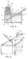
- Figure 8 shows a device having a vessel 10 and foaming chamber 20 similar to that of Figure 6.
- the top end of the foaming chamber 20 has been changed to include a pair of rollers 52 having a profile 53 for shaping the stabilized foam 37 into a new shape 54.
- These rollers 52 may be powered and thereby assist in the lifting of the foam 37 in an upward direction and they may also be water-cooled.
- the profile 53 of the rollers 52 may be shaped such as to form the foam section 54 in circular cross-section, rectangular cross-section, etc.
- Figure 9 shows an embodiment generally similar to that of Figure 7, but in this embodiment a solid plug 50 is inserted into the discharge orifice or mould such as to form the stabilized liquid foam into a hollow profile 51.
- Figure 10 shows a foamed slab product formed on a substantially horizontal moving twin-belt caster.
- this foamed slab some of the liquid metal has drained to the bottom during twin-belt casting and settled on the bottom belt. There it solidified to form the homogeneous, pore-free skin which can be clearly seen along the top of the slab in Figure 10.
Landscapes
- Engineering & Computer Science (AREA)
- Mechanical Engineering (AREA)
- Chemical & Material Sciences (AREA)
- Materials Engineering (AREA)
- Metallurgy (AREA)
- Organic Chemistry (AREA)
- Continuous Casting (AREA)
- Manufacture Of Alloys Or Alloy Compounds (AREA)
- Casting Or Compression Moulding Of Plastics Or The Like (AREA)
Claims (33)
- Verfahren zum Herstellen eines geformten, verfestigten Schaummetallproduktes, wobei der Schaum in einer Schaumkammer geformt wird, indem ein Verbundmaterial aus einer Metallmatrix und fein verteilten, festen Stabilisatorteilchen oberhalb der Solidustemperatur der Metallmatrix erhitzt werden und Gasblasen in das geschmolzene Metallverbundmaterial unterhalb dessen Oberfläche abgelassen werden, um dadurch einen stabilisierten Flüssigschaum an der Oberfläche des geschmolzenen Metallverbundmaterials auszubilden,
wobei der von der Oberfläche des geschmolzenen Metallverbundmaterials austretende, stabilisierte Flüssigschaum kontinuierlich durch eine Formzone mit gegenüberliegenden Formflächen geführt wird, die zwei gegenüberliegende, sich bewegende Bänder, gegenüberliegende Walzen oder ein sich bewegendes Band, das einer Walze gegenüberliegt, aufweisen, wo dieser zu einem Schaumprodukt mit einer gewünschten Querschnittsform geformt wird, oder die in dem Oberteil der Schaumkammer eine geformte Öffnung aufweist, durch die hindurch der stabilisierte Flüssigschaum vertikal angehoben wird, wodurch ein Schaumprodukt mit gewünschter Querschnittsform ausgebildet wird. - Verfahren nach Anspruch 1, wobei der stabilisierte Flüssigschaum ausgebildet wird, indem dieser bewegt wird, während er zwischen einem Paar sich bewegender Bänder gehalten wird.
- Verfahren nach Anspruch 2, wobei der Flüssigschaum verfestigt wird, während sich dieser zwischen den Bändern vertikal nach oben bewegt.
- Verfahren nach Anspruch 2, wobei der Flüssigschaum verfestigt wird, während sich dieser zwischen den Bändern vertikal nach unten bewegt.
- Verfahren nach Anspruch 2, wobei die Bänder Endlosbänder sind.
- Verfahren nach Anspruch 2, wobei mindestens eines der Bänder einen Coil aus flächigem Metall aufweist, das sich mit einer Hauptfläche des Schaumproduktes verbindet.
- Verfahren nach Anspruch 3, wobei die Bänder so angeordnet sind, daß das untere Ende eines zwischen den gegenüberliegenden, sich bewegenden Bändern ausgebildeten Zwischenraums mit dem von der Oberfläche des geschmolzenen Metallverbundmaterials austretenden Flüssigschaum in Eingriff tritt und diesen zwischen den Bändern nach oben zieht.
- Verfahren nach Anspruch 1, wobei der Flüssigschaum verfestigt wird, während sich dieser horizontal oder unter einem Winkel nicht größer als 45° zur Horizontalen zwischen einem Bandpaar bewegt.
- Verfahren nach Anspruch 1, wobei der stabilisierte Flüssigschaum, der von der Oberfläche des geschmolzenen Metallverbundmaterials austritt, durch Durchführen durch eine geformte Öffnung in dem Oberteil der Schaumkammer in eine gewünschte Form gebracht wird, während dieser vertikal nach oben angehoben wird.
- Verfahren nach Anspruch 9, wobei der stabilisierte Flüssigschaum mit Hilfe eines gekühlten Hakenelementes nach oben angehoben wird, das innerhalb des Flüssigschaumes angeordnet ist, der aus der Öffnung austritt.
- Verfahren nach Anspruch 9, wobei der stabilisierte Flüssigschaum, der aus der Öffnung austritt, zwischen Walzen nach oben angehoben wird.
- Verfahren nach Anspruch 10, wobei die Walzen profiliert sind, um das austretende Schaumprodukt in eine gewünschte Form zu formen.
- Verfahren nach Anspruch 9, wobei die Öffnung einen Zentralstopfen enthält, der den Flüssigschaum zu einem Hohlprofil formt.
- Verfahren nach den Ansprüchen 1 bis 13, wobei das Metall Aluminium oder eine Legierung davon ist.
- Verfahren nach Anspruch 9, wobei Teilchen eine Größe in dem Bereich von ca. 0,1 bis 100 µm aufweisen und ausgewählt sind aus Aluminiumoxid, Titandiborid, Zirconiumoxid, Siliciumcarbid und Siliciumnitrid.
- Verfahren nach den Ansprüchen 1 bis 15, wobei die Gasblasen ausgebildet werden, indem unterhalb der Oberfläche des geschmolzenen Metallverbundmaterials ein Gasstrom injiziert wird und die Gasblasen ausgebildet werden, indem dem Gasstrom eine Scherwirkung auferlegt wird.
- Verfahren nach Anspruch 16, wobei die Scherwirkung durch einen sich drehenden Rührflügel erzeugt wird.
- Verfahren nach Anspruch 16, wobei die Scherwirkung durch Zuführen des Gases durch eine sich hin- und herbewegende oder vibrierende Injektionsdüse vorgesehen wird.
- Vorrichtung zum Herstellen einer Platte aus Schaummetall, umfassend einen hitzebeständigen Behälter mit einer Haltekammer zum Halten eines Verbundmaterials aus geschmolzenem Metall und fein verteilten, festen Stabilisatorteilchen und eine Schaumkammer, die mit der Haltekammer strömungsverbunden ist, eine Gasablaßeinrichtung in der Schaumkammer zum Anlassen von Gasblasen in das geschmolzene Metallverbundmaterial unterhalb dessen Oberfläche, und eine Formzone mit gegenüberliegenden Formflächen, die zur Aufnahme von Flüssigschaum von der Oberfläche des Verbundmaterials in der Schaumkammer dienen und den Schaum zu einem verfestigten Schaummetall mit gewünschter Querschnittsform formen, wobei die gegenüberliegenden Formflächen (a) ein Paar von seitlich beabstandeten, bewegbaren Bändern, gegenüberliegende Walzen oder (b) ein bewegbares Band und eine Walze, die seitlich beabstandet sind und sich gegenüberliegen, oder (c) eine Öffnung oder Formeinrichtung in dem Oberteil der Schaumkammer zum Formen von Flüssigschaum aufweisen, der nach oben durch diese gelangt, und eine Hubeinrichtung zum Verbinden mit dem Flüssigschaum, der durch die Öffnung oder Form gelangt.
- Vorrichtung nach Anspruch 19, wobei die gegenüberliegenden Formflächen ein Paar seitlich beabstandeter, bewegbarer Bänder umfassen.
- Vorrichtung nach Anspruch 20, wobei die seitlich beabstandeten Bänder ein Paar von Bändern ist, die oberhalb der Schaumkammer angeordnet sind und zum Anheben des austretenden Flüssigschaums vertikal nach oben zwischen sich dienen.
- Vorrichtung nach Anspruch 21, wobei die Bänder Endlosbänder sind.
- Vorrichtung nach Anspruch 21, wobei mindestens eines der Bänder ein Coil aus flächigem Metall ist, das mit dem Schaum während der Verfestigung verbindbar ist.
- Vorrichtung nach Anspruch 20, wobei die seitlich beabstandeten Bänder ein Paar von Bändern ist, die so angeordnet sind, daß sie Flüssigschaum an ihrem oberen Ende aufnehmen und den Flüssigschaum zwischen sich vertikal nach unten bewegen.
- Vorrichtung nach Anspruch 24, die einen Durchgang aufweist, um Flüssigschaum von dem Oberteil der Schaumkammer in den Raum zwischen den sich nach unten bewegenden Bändern zu führen.
- Vorrichtung nach Anspruch 19, wobei die gegenüberliegenden Formflächen eine Öffnung oder Formeinrichtung an dem Oberteil der Schaumkammer aufweisen, um Flüssigschaum zu formen, der durch diese nach oben gelangt, und eine Hubeinrichtung zum Verbinden mit dem Flüssigschaum, der durch die Öffnung oder Form gelangt.
- Vorrichtung nach Anspruch 26, wobei die Öffnung oder Form einen Einsatz in einem oberen Bereich der Schaumkammer aufweist, der sich nach innen und nach oben verjüngende Seitenwände unterhalb der Öffnung oder Form aufweist.
- Vorrichtung nach Anspruch 26, wobei die Hubeinrichtung ein gekühltes Metallhakenelement aufweist, das für einen Eingriff mit einem Abschnitt und für ein Kühlen eines Abschnitts des Flüssigschaums dient, ausreichend um den Schaum nach oben zu ziehen.
- Vorrichtung nach Anspruch 26, wobei die Öffnung oder Form einen festen Einsatz zum Formen eines Hohlschaummetallprofiles enthält.
- Vorrichtung nach Anspruch 26, wobei mindestens ein Walzenpaar oberhalb der Öffnung oder Form für einen Eingriff mit einem Schaumprofil angeordnet ist, das aus der Öffnung oder Form austritt.
- Vorrichtung nach Anspruch 30, wobei die Walzen derart ausgebildet sind, daß sie das Schaumprofil in eine gewünschte Form formen.
- Vorrichtung nach Anspruch 31, wobei die Walzen angetriebene Walzen sind, die so ausgebildet sind, daß sie das Anheben des Schaumprofiles unterstützen.
- Vorrichtung nach Anspruch 19, wobei die gegenüberliegenden Formflächen ein bewegbares Band umfassen, das zur Aufnahme von Flüssigschaum von der Oberfläche des Verbundmaterials in der Schaumkammer dient, sowie eine oberhalb des Bandes angeordnete Walze, um die Oberfläche einer zu formenden Schaummetallplatte flachzuwalzen.
Applications Claiming Priority (3)
| Application Number | Priority Date | Filing Date | Title |
|---|---|---|---|
| US70870091A | 1991-05-31 | 1991-05-31 | |
| US708700 | 1991-05-31 | ||
| PCT/CA1992/000223 WO1992021457A1 (en) | 1991-05-31 | 1992-05-29 | Process and apparatus for producing shaped slabs of particle stabilized foamed metal |
Publications (2)
| Publication Number | Publication Date |
|---|---|
| EP0587619A1 EP0587619A1 (de) | 1994-03-23 |
| EP0587619B1 true EP0587619B1 (de) | 1996-07-10 |
Family
ID=24846859
Family Applications (1)
| Application Number | Title | Priority Date | Filing Date |
|---|---|---|---|
| EP92910831A Expired - Lifetime EP0587619B1 (de) | 1991-05-31 | 1992-05-29 | Verfahren und vorrichtung zum herstellen profilierter platten aus teilchenstabilisiertem metallschaum |
Country Status (7)
| Country | Link |
|---|---|
| US (1) | US5334236A (de) |
| EP (1) | EP0587619B1 (de) |
| JP (1) | JP3045773B2 (de) |
| AT (1) | ATE140169T1 (de) |
| CA (1) | CA2109957C (de) |
| DE (1) | DE69212157T2 (de) |
| WO (1) | WO1992021457A1 (de) |
Families Citing this family (61)
| Publication number | Priority date | Publication date | Assignee | Title |
|---|---|---|---|---|
| CA2087791A1 (en) * | 1993-01-21 | 1994-07-22 | Martin Thomas | Production of particle-stabilized metal foams |
| FR2713172B1 (fr) * | 1993-12-01 | 1999-04-16 | Volkswagen Ag | Dispositif de sécurité pour véhicules automobiles. |
| JP3868546B2 (ja) * | 1996-09-10 | 2007-01-17 | 独立行政法人科学技術振興機構 | ポーラス銀の製造方法 |
| AT408076B (de) * | 1996-10-07 | 2001-08-27 | Mepura Metallpulver | Verfahren zur herstellung von schaummetall- bzw. schaummetall/metall-verbund-formkörpern, anlage zu deren herstellung und deren verwendung |
| EP1669738A3 (de) * | 1996-10-09 | 2007-12-12 | Symyx Technologies, Inc. | Infrarotspektroskopie und Abbildung von Bibliotheken |
| EP0998589B1 (de) | 1997-07-14 | 2001-10-17 | Dipl.-Ing. Emil Dengler Unternehmensberatung | Verfahren und anlage zur herstellung von "leichtstahl" in form von strangguss unter gaseinschluss |
| US6250362B1 (en) | 1998-03-02 | 2001-06-26 | Alcoa Inc. | Method and apparatus for producing a porous metal via spray casting |
| US6162310A (en) * | 1998-08-05 | 2000-12-19 | Tseng; Shao-Chien | Method for producing porous sponge like metal of which the shapes and sizes of pores are controllable |
| DE19907855C1 (de) | 1999-02-24 | 2000-09-21 | Goldschmidt Ag Th | Herstellung von Metallschäumen |
| DE19908867A1 (de) * | 1999-03-01 | 2000-09-07 | Arved Huebler | Verbundkörper sowie Verfahren zum Herstellen eines Verbundkörpers |
| US6759004B1 (en) * | 1999-07-20 | 2004-07-06 | Southco, Inc. | Process for forming microporous metal parts |
| RU2180361C2 (ru) * | 1999-07-20 | 2002-03-10 | Полькин Игорь Степанович | Способ получения изделий из пеноалюминия |
| US6358345B1 (en) * | 1999-11-16 | 2002-03-19 | Shao-Chien Tseng | Method for producing porous sponge like metal of which density of pores is controllable |
| US6343640B1 (en) * | 2000-01-04 | 2002-02-05 | The University Of Alabama | Production of metal/refractory composites by bubbling gas through a melt |
| NO311708B1 (no) * | 2000-02-25 | 2002-01-14 | Cymat Corp | Fremgangsmåte og utstyr for tildannelse av stöpte produkter |
| DE10042569C1 (de) * | 2000-08-25 | 2002-04-04 | Christian Steglich | Verfahren und Einrichtung zur Herstellung von Verbundwerkstoffen mit einem Kern aus Metallschaum |
| DE10104338A1 (de) * | 2001-02-01 | 2002-08-08 | Goldschmidt Ag Th | Herstellung flächiger, metallischer Integralschäume |
| US6915834B2 (en) | 2001-02-01 | 2005-07-12 | Goldschmidt Ag | Process for producing metal foam and metal body produced using this process |
| DE10104339A1 (de) * | 2001-02-01 | 2002-08-08 | Goldschmidt Ag Th | Verfahren zur Herstellung von Metallschaum und danach hergestellter Metallkörper |
| DE10104340A1 (de) * | 2001-02-01 | 2002-08-08 | Goldschmidt Ag Th | Verfahren zur Herstellung von Mettalschaum und danach hergestellter Metallkörper |
| US6706239B2 (en) | 2001-02-05 | 2004-03-16 | Porvair Plc | Method of co-forming metal foam articles and the articles formed by the method thereof |
| US20040079198A1 (en) * | 2002-05-16 | 2004-04-29 | Bryant J Daniel | Method for producing foamed aluminum products |
| US20040163492A1 (en) * | 2001-05-17 | 2004-08-26 | Crowley Mark D | Method for producing foamed aluminum products |
| ATE357304T1 (de) | 2001-05-19 | 2007-04-15 | Goldschmidt Gmbh | Herstellung von metallschäumen |
| DE10127716A1 (de) | 2001-06-07 | 2002-12-12 | Goldschmidt Ag Th | Verfahren zur Herstellung von Metall/Metallschaum-Verbundbauteilen |
| US7175689B2 (en) * | 2001-06-15 | 2007-02-13 | Huette Klein-Reichenbach Gesellschaft Mbh | Process for producing a lightweight molded part and molded part made of metal foam |
| AT410103B (de) * | 2001-06-15 | 2003-02-25 | Huette Klein Reichenbach Gmbh | Verfahren zur herstellung eines leichtgewichtigen formkörpers und formkörper aus metallschaum |
| JP2003112253A (ja) * | 2001-06-15 | 2003-04-15 | Huette Klein-Reichenbach Gmbh | 泡状金属を製造する装置及び方法 |
| US6660224B2 (en) | 2001-08-16 | 2003-12-09 | National Research Council Of Canada | Method of making open cell material |
| CN1277637C (zh) * | 2001-08-17 | 2006-10-04 | 赛麦特公司 | 低压金属泡沫铸造方法和装置 |
| US7108828B2 (en) | 2001-08-27 | 2006-09-19 | National Research Council Of Canada | Method of making open cell material |
| DE10163489B4 (de) * | 2001-12-21 | 2010-08-19 | Evonik Goldschmidt Gmbh | Flächiger, metallischer Integralschaum |
| CA2474949A1 (en) * | 2002-02-01 | 2003-08-07 | Cymat Corp. | Metal foam casting apparatus and method |
| AU2003208209A1 (en) | 2002-03-04 | 2003-09-16 | Cymat Corp. | Sealed impeller for producing metal foam and system and method therefor |
| US7312985B2 (en) * | 2002-03-08 | 2007-12-25 | Lg Electronics Inc. | Cooler of notebook personal computer and fabrication method thereof |
| AT411970B (de) * | 2002-04-19 | 2004-08-26 | Huette Klein Reichenbach Gmbh | Leichtbauteil, sowie verfahren und vorrichtung zu dessen herstellung |
| AT411768B (de) * | 2002-09-09 | 2004-05-25 | Huette Klein Reichenbach Gmbh | Verfahren und vorrichtung zur herstellung von fliessfähigem metallschaum |
| US6881241B2 (en) * | 2002-11-18 | 2005-04-19 | General Motors Corporation | Method for manufacturing closed-wall cellular metal |
| US7582361B2 (en) * | 2004-06-21 | 2009-09-01 | Purgert Robert M | Lightweight structural members |
| US7328831B1 (en) | 2004-06-25 | 2008-02-12 | Porvair Plc | Method of making a brazed metal article and the article formed thereby |
| EP1772211A1 (de) * | 2005-10-10 | 2007-04-11 | Georg Fischer Fahrzeugtechnik AG | Kokillengiessanlage für Metallschaumformteile |
| WO2008010809A1 (en) * | 2006-07-20 | 2008-01-24 | Intellmat, Llc | Method of forming foamed metal |
| AT504305B1 (de) * | 2006-10-05 | 2009-09-15 | H Tte Klein Reichenbach Ges M | Mehrschichtiger metallformkírper mit einer metallschaummatrix und dessen verwendung |
| DE102007041775B3 (de) * | 2007-09-04 | 2008-10-02 | Eads Deutschland Gmbh | Verfahren zum Herstellen eines Formkörpers mit schaumartiger Struktur |
| ATE539823T1 (de) | 2008-03-05 | 2012-01-15 | Southwire Co | Ultraschallsonde mit schutzschicht aus niobium |
| KR101111286B1 (ko) * | 2008-08-22 | 2012-03-14 | 한국생산기술연구원 | 발포체, 이 발포체의 제조장치, 이 발포체를 이용한 발포금속의 제조방법 및 발포금속 제조장치 |
| HU227545B1 (en) * | 2008-12-04 | 2011-08-29 | Bay Zoltan Alkalmazott Kutatasi Koezalapitvany | Method for producing metal foam |
| US8574336B2 (en) | 2010-04-09 | 2013-11-05 | Southwire Company | Ultrasonic degassing of molten metals |
| US8652397B2 (en) | 2010-04-09 | 2014-02-18 | Southwire Company | Ultrasonic device with integrated gas delivery system |
| CN101818278A (zh) * | 2010-05-14 | 2010-09-01 | 大连海事大学 | 一种用金属熔体充气法制备多孔泡沫金属的设备及其方法 |
| CN102962413A (zh) * | 2012-11-29 | 2013-03-13 | 中南大学 | 一种可获均一泡体闭孔泡沫铝的连续铸造系统 |
| JP6674376B2 (ja) | 2013-11-18 | 2020-04-01 | サウスワイヤー・カンパニー・リミテッド・ライアビリティ・カンパニーSouthwire Company,Llc | 溶融金属の脱ガス用排気口付き超音波プローブ |
| CN103667765B (zh) * | 2014-01-16 | 2016-01-20 | 岳阳钟鼎热工电磁科技有限公司 | 一种泡沫铝合金的连续生产设备 |
| HUE048957T2 (hu) | 2015-02-09 | 2020-09-28 | Hans Tech Llc | Ultrahangos szemcsefinomítás |
| US10233515B1 (en) | 2015-08-14 | 2019-03-19 | Southwire Company, Llc | Metal treatment station for use with ultrasonic degassing system |
| EP3347150B1 (de) | 2015-09-10 | 2020-08-19 | Southwire Company, LLC | Ultraschall-kornveredelungs- und entgasungsvorrichtung für den metallguss |
| CN106180610B (zh) * | 2016-08-30 | 2018-02-27 | 燕山大学 | 一种泡沫金属夹芯材料生产设备及其生产方法 |
| ES2664614B2 (es) * | 2016-10-20 | 2018-10-19 | Alucoil, S.A. | Procedimiento para la obtención de un panel sandwich con espuma de aluminio en el nucleo, instalación y producto obtenido |
| CA3044699A1 (en) | 2016-12-02 | 2018-06-07 | Polyvalor, Limited Partnership | Openly porous acoustic foam, process for manufacture and uses thereof |
| CN109382492B (zh) * | 2018-12-05 | 2021-01-26 | 昆明理工大学 | 一种连续制备颗粒增强金属基复合材料的方法及装置 |
| CN114505453A (zh) * | 2022-02-09 | 2022-05-17 | 安徽省新方尊自动化科技有限公司 | 一种连续生产泡沫铝棒材的装置及方法 |
Family Cites Families (9)
| Publication number | Priority date | Publication date | Assignee | Title |
|---|---|---|---|---|
| FR588825A (fr) * | 1924-11-13 | 1925-05-15 | Procédé d'étirage | |
| FR615147A (fr) * | 1925-09-12 | 1926-12-30 | Produit métallique pour l'obtention d'objets laminés, moulés ou autres, et procédés pour sa fabrication | |
| US3297431A (en) * | 1965-06-02 | 1967-01-10 | Standard Oil Co | Cellarized metal and method of producing same |
| US3941182A (en) * | 1971-10-29 | 1976-03-02 | Johan Bjorksten | Continuous process for preparing unidirectionally reinforced metal foam |
| CH553606A (de) * | 1972-07-27 | 1974-09-13 | Concast Ag | Verfahren und einrichtung zum stranggiessen von metall mit gegenueber dem eingegossenen metall wesentlich geringerem spezifischem stranggewicht. |
| US4049042A (en) * | 1976-03-31 | 1977-09-20 | Gte Laboratories Incorporated | Apparatus for continuous casting |
| DE3516737A1 (de) * | 1985-05-09 | 1986-11-13 | Hoesch Stahl AG, 4600 Dortmund | Verfahren und anlage zum herstellen von mit gasblasen durchsetzten metallischen werkstoffen in form von profilen |
| NO172697C (no) * | 1989-07-17 | 1993-08-25 | Norsk Hydro As | Fremgangsmaate ved fremstilling av partikkelforsterket metallskum og resulterende produkt |
| US4973358A (en) * | 1989-09-06 | 1990-11-27 | Alcan International Limited | Method of producing lightweight foamed metal |
-
1992
- 1992-05-29 EP EP92910831A patent/EP0587619B1/de not_active Expired - Lifetime
- 1992-05-29 WO PCT/CA1992/000223 patent/WO1992021457A1/en not_active Ceased
- 1992-05-29 CA CA002109957A patent/CA2109957C/en not_active Expired - Lifetime
- 1992-05-29 AT AT92910831T patent/ATE140169T1/de not_active IP Right Cessation
- 1992-05-29 DE DE69212157T patent/DE69212157T2/de not_active Expired - Lifetime
- 1992-05-29 JP JP4509739A patent/JP3045773B2/ja not_active Expired - Lifetime
- 1992-06-29 US US07/905,619 patent/US5334236A/en not_active Expired - Lifetime
Also Published As
| Publication number | Publication date |
|---|---|
| DE69212157D1 (de) | 1996-08-14 |
| DE69212157T2 (de) | 1996-11-21 |
| JPH06507579A (ja) | 1994-09-01 |
| EP0587619A1 (de) | 1994-03-23 |
| ATE140169T1 (de) | 1996-07-15 |
| WO1992021457A1 (en) | 1992-12-10 |
| CA2109957A1 (en) | 1992-12-10 |
| JP3045773B2 (ja) | 2000-05-29 |
| CA2109957C (en) | 1998-12-15 |
| US5334236A (en) | 1994-08-02 |
Similar Documents
| Publication | Publication Date | Title |
|---|---|---|
| EP0587619B1 (de) | Verfahren und vorrichtung zum herstellen profilierter platten aus teilchenstabilisiertem metallschaum | |
| EP0666784B1 (de) | Verfahren und vorrichtung zum formgiessen eines mittels teilchen stabilisierten metallschaumes | |
| US4973358A (en) | Method of producing lightweight foamed metal | |
| US5112697A (en) | Stabilized metal foam body | |
| CN110280746B (zh) | 一种单源高强超声辅助铸造大规格2xxx系铝合金圆锭的方法 | |
| KR100592533B1 (ko) | 연속식 발포금속 제조방법 및 장치 | |
| US9168584B2 (en) | Method of producing a metal foam by oscillations and thus obtained metal foam product | |
| JPH09122856A (ja) | 金属連続鋳造用鋳型へ液体金属を導入するための底に孔を有するノズル | |
| CN109536766B (zh) | 一种基于吹气法的半固态浆料制备泡沫铝的方法及装置 | |
| CA2084038A1 (en) | Method and apparatus for producing cellular metal | |
| US6015528A (en) | Apparatus and process for casting metal matrix composite materials | |
| JPS632703B2 (de) | ||
| CN113695537B (zh) | 一种空心铸锭、其制备方法以及空心型材 | |
| EP0387006A2 (de) | Metallbandgiessvorrichtung mit zwei Seitenplatten | |
| US6881241B2 (en) | Method for manufacturing closed-wall cellular metal | |
| JP2003112253A (ja) | 泡状金属を製造する装置及び方法 | |
| SU1191434A1 (ru) | Способ поризации расплавленного материала и устройство дл его осуществлени | |
| JP2808552B2 (ja) | 無機物粒子層と金属の複合部材の連続鋳造方法及び装置 | |
| JPH02121758A (ja) | 鋼の連続鋳造用タンディッシュ | |
| EP0342020A2 (de) | Verfahren und Vorrichtung zum kontinuierlichen Bandgiessen | |
| JPS6340630B2 (de) | ||
| JPH067898A (ja) | 連続鋳造機および連続鋳造法 | |
| JPH067899A (ja) | スラブの連続鋳造機および連続鋳造方法 |
Legal Events
| Date | Code | Title | Description |
|---|---|---|---|
| PUAI | Public reference made under article 153(3) epc to a published international application that has entered the european phase |
Free format text: ORIGINAL CODE: 0009012 |
|
| 17P | Request for examination filed |
Effective date: 19931204 |
|
| AK | Designated contracting states |
Kind code of ref document: A1 Designated state(s): AT BE DE ES FR GB IT NL SE |
|
| 17Q | First examination report despatched |
Effective date: 19950824 |
|
| GRAH | Despatch of communication of intention to grant a patent |
Free format text: ORIGINAL CODE: EPIDOS IGRA |
|
| GRAA | (expected) grant |
Free format text: ORIGINAL CODE: 0009210 |
|
| AK | Designated contracting states |
Kind code of ref document: B1 Designated state(s): AT BE DE ES FR GB IT NL SE |
|
| PG25 | Lapsed in a contracting state [announced via postgrant information from national office to epo] |
Ref country code: NL Free format text: LAPSE BECAUSE OF FAILURE TO SUBMIT A TRANSLATION OF THE DESCRIPTION OR TO PAY THE FEE WITHIN THE PRESCRIBED TIME-LIMIT Effective date: 19960710 Ref country code: IT Free format text: LAPSE BECAUSE OF FAILURE TO SUBMIT A TRANSLATION OF THE DESCRIPTION OR TO PAY THE FEE WITHIN THE PRE;WARNING: LAPSES OF ITALIAN PATENTS WITH EFFECTIVE DATE BEFORE 2007 MAY HAVE OCCURRED AT ANY TIME BEFORE 2007. THE CORRECT EFFECTIVE DATE MAY BE DIFFERENT FROM THE ONE RECORDED.SCRIBED TIME-LIMIT Effective date: 19960710 Ref country code: ES Free format text: THE PATENT HAS BEEN ANNULLED BY A DECISION OF A NATIONAL AUTHORITY Effective date: 19960710 Ref country code: BE Effective date: 19960710 Ref country code: AT Effective date: 19960710 |
|
| REF | Corresponds to: |
Ref document number: 140169 Country of ref document: AT Date of ref document: 19960715 Kind code of ref document: T |
|
| REF | Corresponds to: |
Ref document number: 69212157 Country of ref document: DE Date of ref document: 19960814 |
|
| ET | Fr: translation filed | ||
| PG25 | Lapsed in a contracting state [announced via postgrant information from national office to epo] |
Ref country code: SE Effective date: 19961010 |
|
| NLV1 | Nl: lapsed or annulled due to failure to fulfill the requirements of art. 29p and 29m of the patents act | ||
| PLBE | No opposition filed within time limit |
Free format text: ORIGINAL CODE: 0009261 |
|
| STAA | Information on the status of an ep patent application or granted ep patent |
Free format text: STATUS: NO OPPOSITION FILED WITHIN TIME LIMIT |
|
| 26N | No opposition filed | ||
| REG | Reference to a national code |
Ref country code: GB Ref legal event code: IF02 |
|
| PGFP | Annual fee paid to national office [announced via postgrant information from national office to epo] |
Ref country code: FR Payment date: 20110607 Year of fee payment: 20 |
|
| PGFP | Annual fee paid to national office [announced via postgrant information from national office to epo] |
Ref country code: GB Payment date: 20110525 Year of fee payment: 20 |
|
| PGFP | Annual fee paid to national office [announced via postgrant information from national office to epo] |
Ref country code: DE Payment date: 20110527 Year of fee payment: 20 |
|
| REG | Reference to a national code |
Ref country code: DE Ref legal event code: R071 Ref document number: 69212157 Country of ref document: DE |
|
| REG | Reference to a national code |
Ref country code: DE Ref legal event code: R071 Ref document number: 69212157 Country of ref document: DE |
|
| REG | Reference to a national code |
Ref country code: GB Ref legal event code: PE20 Expiry date: 20120528 |
|
| PG25 | Lapsed in a contracting state [announced via postgrant information from national office to epo] |
Ref country code: DE Free format text: LAPSE BECAUSE OF EXPIRATION OF PROTECTION Effective date: 20120530 |
|
| PG25 | Lapsed in a contracting state [announced via postgrant information from national office to epo] |
Ref country code: GB Free format text: LAPSE BECAUSE OF EXPIRATION OF PROTECTION Effective date: 20120528 |