EP0590160A1 - Machine d'extrusion-soufflage plat, procede d'extrusion-soufflage plat et produit d'extrusion-soufflage plat - Google Patents
Machine d'extrusion-soufflage plat, procede d'extrusion-soufflage plat et produit d'extrusion-soufflage plat Download PDFInfo
- Publication number
- EP0590160A1 EP0590160A1 EP93908118A EP93908118A EP0590160A1 EP 0590160 A1 EP0590160 A1 EP 0590160A1 EP 93908118 A EP93908118 A EP 93908118A EP 93908118 A EP93908118 A EP 93908118A EP 0590160 A1 EP0590160 A1 EP 0590160A1
- Authority
- EP
- European Patent Office
- Prior art keywords
- flattened
- core
- parison
- resin
- die
- Prior art date
- Legal status (The legal status is an assumption and is not a legal conclusion. Google has not performed a legal analysis and makes no representation as to the accuracy of the status listed.)
- Granted
Links
Images











Classifications
-
- B—PERFORMING OPERATIONS; TRANSPORTING
- B29—WORKING OF PLASTICS; WORKING OF SUBSTANCES IN A PLASTIC STATE IN GENERAL
- B29C—SHAPING OR JOINING OF PLASTICS; SHAPING OF MATERIAL IN A PLASTIC STATE, NOT OTHERWISE PROVIDED FOR; AFTER-TREATMENT OF THE SHAPED PRODUCTS, e.g. REPAIRING
- B29C49/00—Blow-moulding, i.e. blowing a preform or parison to a desired shape within a mould; Apparatus therefor
- B29C49/02—Combined blow-moulding and manufacture of the preform or the parison
- B29C49/04—Extrusion blow-moulding
- B29C49/04116—Extrusion blow-moulding characterised by the die
-
- B—PERFORMING OPERATIONS; TRANSPORTING
- B29—WORKING OF PLASTICS; WORKING OF SUBSTANCES IN A PLASTIC STATE IN GENERAL
- B29C—SHAPING OR JOINING OF PLASTICS; SHAPING OF MATERIAL IN A PLASTIC STATE, NOT OTHERWISE PROVIDED FOR; AFTER-TREATMENT OF THE SHAPED PRODUCTS, e.g. REPAIRING
- B29C48/00—Extrusion moulding, i.e. expressing the moulding material through a die or nozzle which imparts the desired form; Apparatus therefor
- B29C48/03—Extrusion moulding, i.e. expressing the moulding material through a die or nozzle which imparts the desired form; Apparatus therefor characterised by the shape of the extruded material at extrusion
- B29C48/07—Flat, e.g. panels
-
- B—PERFORMING OPERATIONS; TRANSPORTING
- B29—WORKING OF PLASTICS; WORKING OF SUBSTANCES IN A PLASTIC STATE IN GENERAL
- B29C—SHAPING OR JOINING OF PLASTICS; SHAPING OF MATERIAL IN A PLASTIC STATE, NOT OTHERWISE PROVIDED FOR; AFTER-TREATMENT OF THE SHAPED PRODUCTS, e.g. REPAIRING
- B29C48/00—Extrusion moulding, i.e. expressing the moulding material through a die or nozzle which imparts the desired form; Apparatus therefor
- B29C48/03—Extrusion moulding, i.e. expressing the moulding material through a die or nozzle which imparts the desired form; Apparatus therefor characterised by the shape of the extruded material at extrusion
- B29C48/09—Articles with cross-sections having partially or fully enclosed cavities, e.g. pipes or channels
- B29C48/11—Articles with cross-sections having partially or fully enclosed cavities, e.g. pipes or channels comprising two or more partially or fully enclosed cavities, e.g. honeycomb-shaped
-
- B—PERFORMING OPERATIONS; TRANSPORTING
- B29—WORKING OF PLASTICS; WORKING OF SUBSTANCES IN A PLASTIC STATE IN GENERAL
- B29C—SHAPING OR JOINING OF PLASTICS; SHAPING OF MATERIAL IN A PLASTIC STATE, NOT OTHERWISE PROVIDED FOR; AFTER-TREATMENT OF THE SHAPED PRODUCTS, e.g. REPAIRING
- B29C48/00—Extrusion moulding, i.e. expressing the moulding material through a die or nozzle which imparts the desired form; Apparatus therefor
- B29C48/03—Extrusion moulding, i.e. expressing the moulding material through a die or nozzle which imparts the desired form; Apparatus therefor characterised by the shape of the extruded material at extrusion
- B29C48/12—Articles with an irregular circumference when viewed in cross-section, e.g. window profiles
-
- B—PERFORMING OPERATIONS; TRANSPORTING
- B29—WORKING OF PLASTICS; WORKING OF SUBSTANCES IN A PLASTIC STATE IN GENERAL
- B29C—SHAPING OR JOINING OF PLASTICS; SHAPING OF MATERIAL IN A PLASTIC STATE, NOT OTHERWISE PROVIDED FOR; AFTER-TREATMENT OF THE SHAPED PRODUCTS, e.g. REPAIRING
- B29C48/00—Extrusion moulding, i.e. expressing the moulding material through a die or nozzle which imparts the desired form; Apparatus therefor
- B29C48/25—Component parts, details or accessories; Auxiliary operations
- B29C48/30—Extrusion nozzles or dies
- B29C48/32—Extrusion nozzles or dies with annular openings, e.g. for forming tubular articles
- B29C48/325—Extrusion nozzles or dies with annular openings, e.g. for forming tubular articles being adjustable, i.e. having adjustable exit sections
-
- B—PERFORMING OPERATIONS; TRANSPORTING
- B29—WORKING OF PLASTICS; WORKING OF SUBSTANCES IN A PLASTIC STATE IN GENERAL
- B29C—SHAPING OR JOINING OF PLASTICS; SHAPING OF MATERIAL IN A PLASTIC STATE, NOT OTHERWISE PROVIDED FOR; AFTER-TREATMENT OF THE SHAPED PRODUCTS, e.g. REPAIRING
- B29C49/00—Blow-moulding, i.e. blowing a preform or parison to a desired shape within a mould; Apparatus therefor
- B29C49/02—Combined blow-moulding and manufacture of the preform or the parison
- B29C49/04—Extrusion blow-moulding
- B29C49/0411—Means for defining the wall or layer thickness
- B29C49/04114—Means for defining the wall or layer thickness for keeping constant thickness
-
- B—PERFORMING OPERATIONS; TRANSPORTING
- B29—WORKING OF PLASTICS; WORKING OF SUBSTANCES IN A PLASTIC STATE IN GENERAL
- B29C—SHAPING OR JOINING OF PLASTICS; SHAPING OF MATERIAL IN A PLASTIC STATE, NOT OTHERWISE PROVIDED FOR; AFTER-TREATMENT OF THE SHAPED PRODUCTS, e.g. REPAIRING
- B29C49/00—Blow-moulding, i.e. blowing a preform or parison to a desired shape within a mould; Apparatus therefor
- B29C49/071—Preforms or parisons characterised by their configuration, e.g. geometry, dimensions or physical properties
-
- B—PERFORMING OPERATIONS; TRANSPORTING
- B29—WORKING OF PLASTICS; WORKING OF SUBSTANCES IN A PLASTIC STATE IN GENERAL
- B29C—SHAPING OR JOINING OF PLASTICS; SHAPING OF MATERIAL IN A PLASTIC STATE, NOT OTHERWISE PROVIDED FOR; AFTER-TREATMENT OF THE SHAPED PRODUCTS, e.g. REPAIRING
- B29C2949/00—Indexing scheme relating to blow-moulding
- B29C2949/07—Preforms or parisons characterised by their configuration
- B29C2949/075—Preforms or parisons characterised by their configuration having at least one internal separating wall
-
- B—PERFORMING OPERATIONS; TRANSPORTING
- B29—WORKING OF PLASTICS; WORKING OF SUBSTANCES IN A PLASTIC STATE IN GENERAL
- B29C—SHAPING OR JOINING OF PLASTICS; SHAPING OF MATERIAL IN A PLASTIC STATE, NOT OTHERWISE PROVIDED FOR; AFTER-TREATMENT OF THE SHAPED PRODUCTS, e.g. REPAIRING
- B29C2949/00—Indexing scheme relating to blow-moulding
- B29C2949/30—Preforms or parisons made of several components
- B29C2949/3006—Preforms or parisons made of several components having tangentially different components within one layer, e.g. longitudinal stripes
-
- B—PERFORMING OPERATIONS; TRANSPORTING
- B29—WORKING OF PLASTICS; WORKING OF SUBSTANCES IN A PLASTIC STATE IN GENERAL
- B29C—SHAPING OR JOINING OF PLASTICS; SHAPING OF MATERIAL IN A PLASTIC STATE, NOT OTHERWISE PROVIDED FOR; AFTER-TREATMENT OF THE SHAPED PRODUCTS, e.g. REPAIRING
- B29C49/00—Blow-moulding, i.e. blowing a preform or parison to a desired shape within a mould; Apparatus therefor
- B29C49/02—Combined blow-moulding and manufacture of the preform or the parison
- B29C49/04—Extrusion blow-moulding
- B29C49/041—Extrusion blow-moulding using an accumulator head
-
- F—MECHANICAL ENGINEERING; LIGHTING; HEATING; WEAPONS; BLASTING
- F24—HEATING; RANGES; VENTILATING
- F24S—SOLAR HEAT COLLECTORS; SOLAR HEAT SYSTEMS
- F24S10/00—Solar heat collectors using working fluids
- F24S10/70—Solar heat collectors using working fluids the working fluids being conveyed through tubular absorbing conduits
- F24S10/73—Solar heat collectors using working fluids the working fluids being conveyed through tubular absorbing conduits the tubular conduits being of plastic material
Definitions
- the present invention relates to a flat blow molding machine, a flat blow molding method and products of flat blow molding to obtain flattened products.
- the present applicant previously developed a flat blow molding machine which does not extrude the cylindrical parison "a”, but extrudes hollow flattened parison, that matches an inner wall of thin metallic molds "b” and "c", from clearance between a planar flattened core and a flattened die surrounding the core so as to mold a hollow plate-like product having a uniform thickness.
- This type of flat blow molding machine is constructed as follows, as shown in Figure 34: an accumulator chamber "e” whose section is flattened is formed in a housing "d” in a vertical direction, a planar flattened mandrel “f” is vertically provided at the center of the accumulator chamber “e” and a flattened piston “g” is fitted over the flattened mandrel "f”.
- the flattened piston "g” is lowered by a hydraulic cylinder “h” to pressurize the resin in the accumulator chamber “e” and the pressurized resin is extruded in the form of hollow flattened parison "k” from clearance between a flattened core "i” provided at a tip of the flattened mandrel “f” and a flattened die “j” provided at a lower end of the housing "d".
- the resin is fed to the accumulator chamber “e” from extruders "q" provided on left and right sides in its thickness Y direction.
- the flattened parison "k” extruded as shown in Figure 35 is sandwiched by flattened metallic molds (not shown) in a direction perpendicular to the drawing sheet and air is blown therein.
- a first object of the present invention which is developed in consideration of the above is to provide a flat blow molding machine which can change width of flattened parison injected from the molding machine.
- a second object is to provide a flat blow molding machine which can reduce unnecessary flashes to raise the productivity when manufacturing a product having a width smaller than flattened parison injected from clearance between a flattened die and a flattened core.
- a third object is to provide a flat blow molding machine which can uniformalize resin pressure in an accumulator chamber in a width direction so as to inject flattened parison having no bending.
- a fourth object is to provide a flat blow molding machine which prevents bending and offsetting of a flattened mandrel so as to inject flattened parison having uniform thickness (wall thickness) and no bending.
- a fifth object is to provide a blow molding machine which allows division of a housing for easy cleaning when color and/or material of the resin should be changed.
- a sixth object is to provide blow molding method, apparatus and products which can prevent the injected hollow flattened parison from being deformed due to the swell effect and drawdown.
- a seventh object is to provide curved blow molding method and product which can manufacture products using a small molding machine without deteriorating strength and appearance when a curved (three dimensional) blow molded product whose interior is divided in the direction of injection is manufactured.
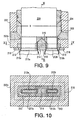
- a first invention provides a flat blow molding machine which injects hollow flattened parison from clearance between a flattened core and a flattened die surrounding the core, characterized in that both ends of the die are slidable with respect to its center in a width direction and in that the core is replaceable (or interchangeable) upon expansion/contraction of the die in the width direction.
- the flattened core may include a planar replaceable part located at the center and curved non-replaceable parts located at the ends, and only the replaceable part may be replaced upon expansion/contraction of the die in the width direction.
- the ends of the die are slid in the width direction respectively and the core is appropriately replaced upon the expansion/contraction of the die in the width direction, it is possible to change the width of the hollow flattened parison to be injected from the clearance between the core and the die.
- the flattened core includes a replaceable planar part and non-replaceable curved parts and only the replaceable part is loaded and unloaded, the cost is reduced since preparing a plurality of replaceable planar parts having different lengths, which are less costly to manufacture, is sufficient.
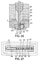
- a second invention provides a flat blow molding machine which injects hollow flattened parison having an enlarged width from clearance between a planar flattened core and a flattened die surrounding the core, characterized in that the flat core is divided into a plurality of pieces in the width direction and an intermediate piece is located between each adjacent core pieces such that the core pieces and the intermediate pieces form parison injection openings.
- the hollow flattened parison injected from the clearance between the flattened die and the flattened core is divided by the intermediate pieces so that a plurality of flattened parison is simultaneously injected.
- no parison is injected below the intermediate pieces so that flashes are reduced to the minimum and cost is in turn reduced.
- the width and the number of the intermediate pieces are changed with the width of the product, it is possible to cope with various kinds and widths of products and the productivity is improved.
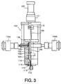
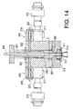
- a third invention provides a flat blow molding machine wherein an accumulator chamber having a flattened section is vertically formed in a housing, a planar flattened mandrel is located at a center of the accumulator chamber, a flattened piston is fit over the flattened mandrel and the flattened piston is lowered to press resin in the accumulator chamber so that the resin is injected in the form of hollow flattened parison from clearance between a flattened core located at a tip of the flattened mandrel and a flattened die located at a lower end of the housing, characterized in that a plurality of resin supply passages are formed in the housing at intervals in a width direction of the accumulator chamber for guiding the resin into the accumulator chamber and in that a flow rate control valve is provided in each resin supply passage.
- a flat blow molding machine wherein an accumulator chamber having a flattened section is vertically formed in a housing, a planar flattened mandrel is located at a center of the accumulator chamber, a flattened piston is fit over the flattened mandrel and the flattened piston is lowered to press resin in the accumulator chamber so that the resin is injected in the form of hollow flattened parison from clearance between a flattened core located at a tip of the flattened mandrel and a flattened die located at a lower end of the housing, characterized in that a resin supply groove is vertically formed in a lateral face of the flattened piston and in that a resin distributing groove which expands downward like a hanger (or fan) in a width direction of the accumulator chamber is formed at a lower end of the resin supply groove.
- the resin filled in the flattened accumulator chamber flows through the resin supply passages formed at intervals in the width direction of the accumulator chamber and reaches the accumulator chamber while its flow rate being appropriately adjusted by the flow rate control valves in the respective supply passages. Owing to this, the resin pressure in the accumulator chamber becomes substantially uniform in the width direction thereof so that it is possible to inject flattened parison having no bending.
- the resin flowing in the resin supply groove which is formed vertically in the lateral face of the flattened piston, and directed to the flattened accumulator chamber below the groove passes through the hanger-type resin distribution groove subsequent to the supply groove to be distributed in the width direction and reaches the flattened accumulator chamber.
- the pressure of the resin filled in the accumulator chamber becomes substantially uniform in the width direction and accordingly it is possible to inject hollow flat parison without bending.
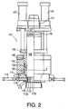
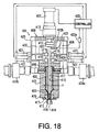
- a fourth invention provides a flat blow molding machine wherein an accumulator chamber having a flattened section is vertically formed in a housing, a planar flattened mandrel is vertically located at a center of the accumulator chamber, a flattened piston is fit over the flattened mandrel and the flattened piston is vertically moved to press resin in the accumulator chamber so that the resin is injected in the form of hollow flattened parison from clearance between a flattened core located at a tip of the flattened mandrel and a flattened die located at a lower end of the housing, characterized in that presser rolls are provided at left and right ends of the flattened mandrel above the accumulator chamber for sandwiching the flattened mandrel to prevent deflection and offsetting of the flattened mandrel and in that an actuator is provided for separating the presser roll from the flattened mandrel to prevent contact of the flattened piston with the presser rolls when
- the presser rolls sandwich the flattened mandrel above the accumulator chamber from left and right so that the position of the flattened mandrel is maintained at the center of the accumulator chamber. Therefore, the deflection and offsetting of the flattened mandrel are reduced. Further, when the flattened piston extending through the flattened mandrel is raised, the actuator separates the presser rolls from the flattened mandrel so that contact and interference between the raised flattened piston and the presser rolls are prevented.
- a fifth invention provides a flat blow molding machine wherein an accumulator chamber filled with resin is vertically formed in a housing and the resin in the accumulator chamber is pressed by a piston to inject the resin in the form of hollow parison from clearance between a core and a die surrounding the core, characterized in that the housing is divided into right and left housing pieces in a height direction of the accumulator chamber and in that an actuator is provided for separating/combining these right and left housing pieces.
- the accumulator chamber is divided to the right and left housing pieces by the actuator and the resin adhering inside can be removed. This considerably simplifies cleaning of the interior.
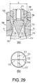
- a sixth invention provides a flat blow molding method for injecting parison in the form of wide and hollow flattened parison from clearance between a planar flattened core and a flattened die surrounding the core, characterized in that a plurality of resin passage grooves which connect left and right faces of the core are formed at the tip of the flattened core in parison injecting direction and at intervals in a width direction of the core and in that the resin which has passed the resin passage grooves forms partition walls in the hollow flattened parison as the hollow flattened parison is injected from the clearance between the flattened core and the flattened die surrounding the core.
- the present invention provides a flat blow molding machine for injecting parison in the form of wide and hollow flattened parison from clearance between a planar flattened core and a flattened die surrounding the core, characterized in that a plurality of resin passage grooves connecting left and right faces of the core are formed at the tip of the flattened core in parison injecting direction and at intervals in the width direction of the core to form partition walls in the injected hollow flattened parison.
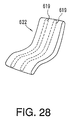
- the present invention provides a blow molded product which is made by injecting parison in the form of wide and hollow flattened parison from clearance between a planar flattened core and a flattened die surrounding the core, sandwiching the parison by a metallic mold and injecting air inside, characterized in that the product is made by forming a plurality of resin passage grooves connecting left and right faces of the core at the tip of the flattened core in parison injecting direction and at intervals in the width direction of the core, injecting the hollow flattened parison from the clearance between the flattened core and the flattened die surrounding the core, forming a plurality of partition walls at intervals in the width direction inside the hollow flattened parison using the resin which has passed the resin passage grooves, sandwiching the parison by the metallic mold and injecting air therein.
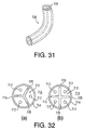
- a seventh invention provides a flat blow molding method for injecting hollow circular parison from clearance between a cylindrical core and a cylindrical die surrounding the core, sandwiching the parison by a metallic mold and injecting air in the parison, characterized in that resin passage grooves which guide the resin from a lateral face of the core toward a center of the core are radiantly formed at a tip of the core in parison injection direction, in that a partition wall is formed by the resin, which passes the resin passage grooves, inside the hollow circular parison as the hollow circular parison is injected from the clearance between the core and the die surrounding the core, and in that the parison is air blown in the metallic mold.
- the present invention provides a blow molding machine wherein hollow circular parison is injected from clearance between a cylindrical core and a cylindrical die surrounding the core, the parison is sandwiched by a metallic mold and air is blown in the parison, characterized in that resin passage grooves for guiding the resin from a lateral face of the core toward a center of the core are radiantly formed at a tip of the core in parison injection direction to form a partition wall inside the injected hollow circular parison.
- the present invention provides a blow-molded product which is generally made by injecting hollow circular parison from clearance between a cylindrical core and a cylindrical die surrounding the core, sandwiching the parison by a metallic mold and injecting air in the parison, characterized in that the product is made by radiantly forming resin passage grooves for guiding the resin from a lateral face of the core toward a center of the core at a tip of the core in parison injection direction, injecting the hollow circular parison from the clearance between the core and the die surrounding the core, form a partition wall in the hollow circular parison by the resin which passes the resin passage grooves and air blowing the parison in the metallic mold.
- part of the resin on the lateral face of the core passes through the resin passage grooves formed radiantly at the core tip and is guided toward the core center as the hollow circular parison is injected from the clearance between the core and the die, so that the partition walls are formed in the hollow circular parison.
- the use of multi-injection head is not necessary so that the apparatus can be designed compact as a whole.
- trace of grooves do not remain in a product which is conventionally produced when the pushing plate is drawn out of the parison. This improves appearance and strength.
- the present invention is suitable for application to a flat blow molding machine, a flat blow molding method and a product of flat blow molding.
Landscapes
- Engineering & Computer Science (AREA)
- Mechanical Engineering (AREA)
- Manufacturing & Machinery (AREA)
- Physics & Mathematics (AREA)
- Geometry (AREA)
- Blow-Moulding Or Thermoforming Of Plastics Or The Like (AREA)
- Processing And Handling Of Plastics And Other Materials For Molding In General (AREA)
Abstract
Applications Claiming Priority (13)
| Application Number | Priority Date | Filing Date | Title |
|---|---|---|---|
| JP9970892A JP3106677B2 (ja) | 1992-04-20 | 1992-04-20 | 偏平ブロー成形装置 |
| JP99708/92 | 1992-04-20 | ||
| JP122111/92 | 1992-05-14 | ||
| JP04122111A JP3118954B2 (ja) | 1992-05-14 | 1992-05-14 | 偏平ブロー成形装置 |
| JP12745992A JP3196316B2 (ja) | 1992-05-20 | 1992-05-20 | ブロー成形装置 |
| JP127459/92 | 1992-05-20 | ||
| JP13362492A JPH05318563A (ja) | 1992-05-26 | 1992-05-26 | ブロー成形方法ならびに成形装置および成形品 |
| JP133624/92 | 1992-05-26 | ||
| JP162996/92 | 1992-06-22 | ||
| JP16299692A JP3196326B2 (ja) | 1992-06-22 | 1992-06-22 | 偏平ブロー成形装置 |
| JP175492/92 | 1992-07-02 | ||
| JP17549292A JP3125443B2 (ja) | 1992-07-02 | 1992-07-02 | 偏平ブロー成形装置 |
| PCT/JP1993/000509 WO1993020997A1 (fr) | 1992-04-20 | 1993-04-20 | Machine d'extrusion-soufflage plat, procede d'extrusion-soufflage plat et produit d'extrusion-soufflage plat |
Publications (3)
| Publication Number | Publication Date |
|---|---|
| EP0590160A1 true EP0590160A1 (fr) | 1994-04-06 |
| EP0590160A4 EP0590160A4 (fr) | 1994-11-23 |
| EP0590160B1 EP0590160B1 (fr) | 1998-04-08 |
Family
ID=27565525
Family Applications (1)
| Application Number | Title | Priority Date | Filing Date |
|---|---|---|---|
| EP93908118A Expired - Lifetime EP0590160B1 (fr) | 1992-04-20 | 1993-04-20 | Machine d'extrusion-soufflage plat, procede d'extrusion-soufflage plat et produit d'extrusion-soufflage plat |
Country Status (1)
| Country | Link |
|---|---|
| EP (1) | EP0590160B1 (fr) |
Cited By (1)
| Publication number | Priority date | Publication date | Assignee | Title |
|---|---|---|---|---|
| GB2282099B (en) * | 1993-09-16 | 1997-09-10 | Saiag Ind Spa | A method and a device for producing connecting hoses and a hose thus produced |
Family Cites Families (5)
| Publication number | Priority date | Publication date | Assignee | Title |
|---|---|---|---|---|
| JPS4936387Y1 (fr) * | 1969-08-06 | 1974-10-03 | ||
| JPS5030958A (fr) * | 1973-07-18 | 1975-03-27 | ||
| IT1037808B (it) * | 1975-05-02 | 1979-11-20 | Covema Srl | Impianto per la realizzazione particolarmente di profilati cavi in materia plastica |
| JPS6392416A (ja) * | 1986-10-07 | 1988-04-22 | Ishikawajima Harima Heavy Ind Co Ltd | ブロ−成形機におけるパリソンの肉厚調整装置 |
| JPH0796256B2 (ja) * | 1989-10-24 | 1995-10-18 | 宇部興産株式会社 | 扁平ダイスを有するブロー成形機 |
-
1993
- 1993-04-20 EP EP93908118A patent/EP0590160B1/fr not_active Expired - Lifetime
Cited By (1)
| Publication number | Priority date | Publication date | Assignee | Title |
|---|---|---|---|---|
| GB2282099B (en) * | 1993-09-16 | 1997-09-10 | Saiag Ind Spa | A method and a device for producing connecting hoses and a hose thus produced |
Also Published As
| Publication number | Publication date |
|---|---|
| EP0590160A4 (fr) | 1994-11-23 |
| EP0590160B1 (fr) | 1998-04-08 |
Similar Documents
| Publication | Publication Date | Title |
|---|---|---|
| EP1864782B1 (fr) | Procédé de fabrication de corps creux en matière synthétique thermoplastique avec des pièces d'insertion situeés à l'intérieur et /ou l'extérieur | |
| EP2026947B1 (fr) | Procédé de fabrication de corps creux à partir de matière thermoplastique par moulage par extrusion-soufflage avec ajustement continu de l'ouverture des buses | |
| CN1197421A (zh) | 用于扁平流道可变边界的装置以及几何形状可变的熔融线料的出料方法 | |
| CN110167741B (zh) | 橡胶挤出装置及橡胶挤出物的制造方法 | |
| US5785920A (en) | Extrusion molding apparatus and method of forming a parison | |
| DE69516591T2 (de) | Verfahren zum Herstellen von blasgeformten Gegenständen | |
| EP2148773B1 (fr) | Dispositif et procede pour la fabrication d'articles en plastique par extrusion-soufflage | |
| EP2173533A2 (fr) | Procédé de réalisation de corps creux moulés par soufflage | |
| US6033204A (en) | Flat blow molding machine, flat blow method and products of flat blow molding | |
| EP1884342A2 (fr) | Dispositif et procédé destinés à la fabrication de corps creux à partir de matières synthétiques thermoplastiques dans un procédé de soufflage | |
| EP1536937B1 (fr) | Procede et dispositif de tirage de produits d'extrusion, en particulier avec alignement de la tireuse a chenilles sur l'axe d'extrusion | |
| DE4306045C2 (de) | Blasformungsverfahren für harzartige Formprodukte und Vorrichtung dafür | |
| DE3429141C2 (de) | Verfahren zur Herstellung eines Hohlkörpers | |
| KR101134945B1 (ko) | 압출다이유닛 | |
| DE202006013751U1 (de) | Vorrichtung zur Herstellung von bandförmigen Kunststoffvorformlingen | |
| EP0590160B1 (fr) | Machine d'extrusion-soufflage plat, procede d'extrusion-soufflage plat et produit d'extrusion-soufflage plat | |
| EP3580035B1 (fr) | Dispositif et procédé pour transformer des préformes en matière plastique en bouteilles en matière plastique comprenant une partie fond mobile | |
| WO2004054782A1 (fr) | Procede de production de profiles creux et installation permettant de mettre en oeuvre ce procede | |
| WO1993020997A1 (fr) | Machine d'extrusion-soufflage plat, procede d'extrusion-soufflage plat et produit d'extrusion-soufflage plat | |
| CN222495047U (zh) | 一种硫化成型模具脱料机构 | |
| DE102007019199A1 (de) | Verfahren zur Herstellung blasgeformter Hohlkörper und Extrusionswerkzeug zur Durchführung des Verfahrens | |
| JP3196326B2 (ja) | 偏平ブロー成形装置 | |
| JP5004550B2 (ja) | 曲部を有する樹脂チューブの製造方法 | |
| JPH0342228A (ja) | 中空長尺物吹込成形装置 | |
| JPH05301272A (ja) | 偏平ブロー成形機のギャップコントロール装置 |
Legal Events
| Date | Code | Title | Description |
|---|---|---|---|
| PUAI | Public reference made under article 153(3) epc to a published international application that has entered the european phase |
Free format text: ORIGINAL CODE: 0009012 |
|
| 17P | Request for examination filed |
Effective date: 19940118 |
|
| AK | Designated contracting states |
Kind code of ref document: A1 Designated state(s): DE FR GB IT |
|
| A4 | Supplementary search report drawn up and despatched | ||
| AK | Designated contracting states |
Kind code of ref document: A4 Designated state(s): DE FR GB IT |
|
| 17Q | First examination report despatched |
Effective date: 19960626 |
|
| GRAG | Despatch of communication of intention to grant |
Free format text: ORIGINAL CODE: EPIDOS AGRA |
|
| GRAG | Despatch of communication of intention to grant |
Free format text: ORIGINAL CODE: EPIDOS AGRA |
|
| GRAH | Despatch of communication of intention to grant a patent |
Free format text: ORIGINAL CODE: EPIDOS IGRA |
|
| GRAH | Despatch of communication of intention to grant a patent |
Free format text: ORIGINAL CODE: EPIDOS IGRA |
|
| GRAA | (expected) grant |
Free format text: ORIGINAL CODE: 0009210 |
|
| AK | Designated contracting states |
Kind code of ref document: B1 Designated state(s): DE FR GB IT |
|
| REF | Corresponds to: |
Ref document number: 69317842 Country of ref document: DE Date of ref document: 19980514 |
|
| ITF | It: translation for a ep patent filed | ||
| ET | Fr: translation filed | ||
| PLBE | No opposition filed within time limit |
Free format text: ORIGINAL CODE: 0009261 |
|
| STAA | Information on the status of an ep patent application or granted ep patent |
Free format text: STATUS: NO OPPOSITION FILED WITHIN TIME LIMIT |
|
| 26N | No opposition filed | ||
| REG | Reference to a national code |
Ref country code: GB Ref legal event code: IF02 |
|
| PGFP | Annual fee paid to national office [announced via postgrant information from national office to epo] |
Ref country code: FR Payment date: 20050408 Year of fee payment: 13 |
|
| PGFP | Annual fee paid to national office [announced via postgrant information from national office to epo] |
Ref country code: DE Payment date: 20050414 Year of fee payment: 13 |
|
| PGFP | Annual fee paid to national office [announced via postgrant information from national office to epo] |
Ref country code: GB Payment date: 20050420 Year of fee payment: 13 |
|
| PG25 | Lapsed in a contracting state [announced via postgrant information from national office to epo] |
Ref country code: GB Free format text: LAPSE BECAUSE OF NON-PAYMENT OF DUE FEES Effective date: 20060420 |
|
| PGFP | Annual fee paid to national office [announced via postgrant information from national office to epo] |
Ref country code: IT Payment date: 20060430 Year of fee payment: 14 |
|
| PG25 | Lapsed in a contracting state [announced via postgrant information from national office to epo] |
Ref country code: DE Free format text: LAPSE BECAUSE OF NON-PAYMENT OF DUE FEES Effective date: 20061101 |
|
| GBPC | Gb: european patent ceased through non-payment of renewal fee |
Effective date: 20060420 |
|
| REG | Reference to a national code |
Ref country code: FR Ref legal event code: ST Effective date: 20061230 |
|
| PG25 | Lapsed in a contracting state [announced via postgrant information from national office to epo] |
Ref country code: FR Free format text: LAPSE BECAUSE OF NON-PAYMENT OF DUE FEES Effective date: 20060502 |
|
| PG25 | Lapsed in a contracting state [announced via postgrant information from national office to epo] |
Ref country code: IT Free format text: LAPSE BECAUSE OF NON-PAYMENT OF DUE FEES Effective date: 20070420 |