EP0590410A1 - Dispositif et système modulaire pour faire passer des câbles à travers des cloisons et des écrans - Google Patents
Dispositif et système modulaire pour faire passer des câbles à travers des cloisons et des écrans Download PDFInfo
- Publication number
- EP0590410A1 EP0590410A1 EP93114828A EP93114828A EP0590410A1 EP 0590410 A1 EP0590410 A1 EP 0590410A1 EP 93114828 A EP93114828 A EP 93114828A EP 93114828 A EP93114828 A EP 93114828A EP 0590410 A1 EP0590410 A1 EP 0590410A1
- Authority
- EP
- European Patent Office
- Prior art keywords
- cable
- metal
- packing system
- metal cushion
- cushion
- Prior art date
- Legal status (The legal status is an assumption and is not a legal conclusion. Google has not performed a legal analysis and makes no representation as to the accuracy of the status listed.)
- Granted
Links
Images

Classifications
-
- H—ELECTRICITY
- H02—GENERATION; CONVERSION OR DISTRIBUTION OF ELECTRIC POWER
- H02G—INSTALLATION OF ELECTRIC CABLES OR LINES, OR OF COMBINED OPTICAL AND ELECTRIC CABLES OR LINES
- H02G3/00—Installations of electric cables or lines or protective tubing therefor in or on buildings, equivalent structures or vehicles
- H02G3/22—Installations of cables or lines through walls, floors or ceilings, e.g. into buildings
Definitions
- the invention relates to a device and a packing system for the implementation of cables in bulkhead or shield walls with electrical contacting for grounding and shielding the cable shield.
- the outer cable sheath and any other existing inner sheaths are removed over a length of several centimeters, so that the cable shields are exposed.
- the cable shields with a potential-free Earth contact introduced a silver potting compound based on a synthetic resin casting compound filled with silver particles. After this silver casting compound has hardened, a functional contacting of the cable shields with a potential-free earth contact is to be ensured.
- Another not insignificant disadvantage is the risk that can exist with silver casting compounds that there is a chemical incompatibility of the synthetic resin casting system with the sheath and the insulation materials of the cable, which in turn can lead to the destruction of the cable with high consequential damage. This is particularly the case when cables and silver casting compounds from different manufacturers are not chemically matched to one another.
- the invention is therefore primarily based on the object of designing a device for carrying cables through shielding device walls, shield rooms and bulkheads in such a way that electrical contacting of the cable shield or shields without excessive losses of the shielding effect while maintaining the known cable-fixing and sealing functions is permanently ensured.
- this object is achieved in that the partitioning modules located in a packing system - elements for fastening cables in leadthroughs and for sealing these leadthroughs - are equipped with a metal cushion that is particularly well suited for contacting braided shields on cables in such a way that The simplest assembly handling ensures permanent contact to the cable shield or shields. Electrical interference power is dissipated via a connecting terminal which is provided with a contact spring.
- the metal cushion guarantees permanent and reliable contacting even when the system is subjected to high dynamic loads due to vibrations of the cables or vibrations that are introduced via the bulkhead or shield walls. The contact can be made without opening the braided cable shield and without heating the cable, as occurs with soldered connections.
- the good metallic conductivity of the metal cushions made from individual heavy-duty wires can also be achieved through the use of certain copper alloys and / or through a galvanic surface coating of the individual wires, e.g. can be improved with tin or silver.
- a suitable galvanic surface coating can provide excellent and permanent protection against corrosion and aging of the metal cushion against aggressive environmental conditions.
- the shape of the metal cushion can be designed in terms of production technology in such a way that an optimal adaptation to the respective cable contour is ensured and a surface contact of the cable shield that is sufficient for the various requirements of the shielding effect is achieved.
- the metal cushion can be designed in this way that a round contact on 360 ° of the cable circumference is possible.
- the flexibility of the metal cushion can also be varied to a great extent by the wire material used, the individual wire diameter and the packing density. This ensures that depending on the cable type and the cable diameter above the screen at a given contact pressure there is a precisely defined spring action of the metal cushion to compensate for certain dimensional tolerances of the cable and to ensure permanent contact despite these dimensional fluctuations.
- the elastic properties of the metal cushion are retained even in a high temperature range. Temperature ranges from -90 ° C to +400 ° C can be covered with these metal cushions.
- connection of the metal cushion to the connection terminal is preferably made by a central contact as a solder connection.
- a ring-shaped metal cushion can also be connected to the connecting terminal from the inside via spot welding. This means that the electrical interference power is always derived with little resistance.
- the molded body that surrounds the metal cushion can be produced, for example, from a thermoplastic by the injection molding process.
- a thermoplastic by the injection molding process.
- a halogen-free and flame-retardant thermoplastic is used as the material for this, which guarantees a high degree of functional reliability in the event of a fire. This is particularly important since the outer sheath and possibly also other inner sheaths of the cable have been removed for contacting the cable shield. Thanks to the halogen-free and flame-retardant module material, this particularly vulnerable cable area can be protected for a reasonable time even in the event of a fire.
- the bulkhead modules are dimensioned in such a way that several module units can be held together as a packing system in a stenter, preferably made of steel. Different module dimensions for different cable dimensions are coordinated so that a compact design is possible.
- the individual partitioning modules have a good electrical connection with one another via the contact spring incorporated in the connecting terminal, so that in this way electrical shielding currents can be derived directly into the metal stenter frame or into a contact strip arranged in the stenter frame.
- the invention is also intended to achieve the object of creating a complete packing system, which consists of a stenter frame, cable-carrying modules, filling modules, anchoring washers, intermediate plates and an end seal, with the same improved shielding properties for electrical currents to a ground potential. Furthermore, with this packing system, the area not occupied by cables in the passage area is completely sealed against high-frequency electromagnetic interference.
- the end seal should consist of a centrally divided plastic body, with one attached between the plastic body halves and with them e.g. metal cushion connected by adhesive and having a protrusion from the modules underneath, on which a steel plate with a circumferential, highly flexible HF end seal is mounted opposite the clamping screw of the packing system.
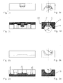
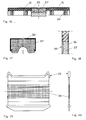
- the metal cushion which is located in the center of the upper partition module half, is denoted by 1 and the connecting terminal by 2.
- the contact spring 3 is laterally incorporated into the connecting terminal 2.
- a recess corresponding to the dimensions of the connecting terminal is provided for the connecting terminal 2 and for the contact spring 3 so that the molded body 4 and the connecting terminal 2 form a contour that is true to the contour.
- the molded body 4 in the area of the contact spring 3 is provided with an elongated recess 5 (FIG.
- the central contact 8 for connecting the metal pad 1 to the connecting terminal 2 is shown in FIG. 3 as a solder joint.
- the outside diameter of the cable 9 held in the partitioning module which is shown with four wire pairs, is designated D1 and represents the dimension for the inlet and outlet openings of the upper molded body 4 and the lower molded body 10.
- D1 The outside diameter of the cable 9 held in the partitioning module, which is shown with four wire pairs, is designated D1 and represents the dimension for the inlet and outlet openings of the upper molded body 4 and the lower molded body 10.
- D2 In the lower molded body 10, with only partial shield contacting in the area opposite the metal cushion 1 embedded in the upper molded body 4, a rounding with the diameter D2 is provided.
- the diameter D2 corresponds to the diameter of the cable 9 above the cable shield 11.
- Fig. 4 shows the version with complete shield contacting (all-round contacting).
- the contacting is achieved by a corresponding design of the metal cushion 1 in the upper partition module half 4 and the metal cushion 19 in the lower partition module half 10.
- the contact between the metal cushions is ensured by pressing the two bulkhead module halves over the end seal 13 and 14 and a corresponding excess in the height of the two metal cushions 1 and 19.
- the contact of the partitioning modules in the installed state is ensured in that the contact spring 3 contacts the surface 18 by pressing.
- filling modules 15 are used at these vacancies.
- the filling modules 15 are also with a Connection terminal 2 in which a contact spring 3 is incorporated. This ensures that, regardless of the position of the partitioning module in the packing system, the shielding currents can also be derived via the filling modules 15 onto the contact strip 7.
- the contact strip 7 is provided with a through hole 16 at its outlet from the clamping frame 6. A connection to a potential-free grounding contact can always be established in this way if the tensioning frame is anchored via the fastening points 17, for example in masonry.
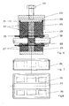
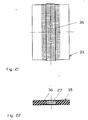
- the packing system consists of the clamping frame housing 23 with the clamping screw 24 for the end seal 25, which is composed of the plastic bodies 26 with the metal cushion 27, the steel plate 28 and the HF end seal 21.
- the modules 22 for the passage of the cables 30, the filling modules 29, which are fixed in the clamping frame by anchoring disks 20, are arranged in the clamping frame 23. In the arrangement shown, the entire breakthrough point in the bulkhead is sealed for high-frequency radiation by contacting the metal cushions 27. Flame resistance, gas and water tightness etc. are guaranteed with the system.
- FIGS. 7 to 9 The end seal of the individual elements of the packing system is shown in FIGS. 7 to 9, which essentially consists of a plastic body 26 which is divided in the middle, a metal cushion 27 which lies between the body halves and is connected to them, for example, by adhesive bonding. It can be seen that the metal cushion has a protrusion of about 2 mm compared to the modules below.
- a highly flexible HF seal 21 is attached under the pressure plate 28, as can be seen in particular in FIGS. 9 and 10. this ensures that there is HF tightness in all three axes over the entire stenter frame.
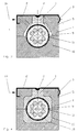
- FIGS. 11 to 13 show the upper part of a module for the cable entry. The lower part of this module would be trained accordingly.
- the metal cushion 27 is formed such that the core bore is, for example, 12 mm in the unloaded state.
- the metal cushion is pressed sufficiently against the braid.
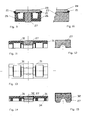
- the metal cushion 27 is mounted in a cage 32 in FIGS. 14 and 15 and, as can be seen, the plastic bodies 31 are injection molded onto this cage. 16 and 17, the cage 33 covers the plastic body 31 and the metal cushion 27 as a whole. One can also see here the sealing grooves 34 for the cable that is passed through.
- FIGS. 19 to 21 An anchoring washer 20 for the modules in the clamping frame is shown in FIGS. 19 to 21. It can be seen that the anchoring washers 20 are divided in the middle and the parts are connected to one another with a metal cushion. The fastening of the plastic halves with the metal cushion is achieved in that a fine-mesh metal fabric 36 is pressed into the two plastic halves.
- the intermediate plates 35 are constructed accordingly, as can be seen in FIGS. 21 and 22.
Landscapes
- Engineering & Computer Science (AREA)
- Architecture (AREA)
- Civil Engineering (AREA)
- Structural Engineering (AREA)
- Installation Of Indoor Wiring (AREA)
- Buffer Packaging (AREA)
Applications Claiming Priority (4)
| Application Number | Priority Date | Filing Date | Title |
|---|---|---|---|
| DE19924232571 DE4232571A1 (de) | 1992-09-29 | 1992-09-29 | Vorrichtung zur Durchführung von Kabeln durch Schott- bzw. Schirmwände |
| DE4232571 | 1992-09-29 | ||
| DE4305071A DE4305071A1 (de) | 1992-09-29 | 1993-02-19 | Packsystem für die Durchführung von Kabeln durch Schirmwände |
| DE4305071 | 1993-02-19 |
Publications (2)
| Publication Number | Publication Date |
|---|---|
| EP0590410A1 true EP0590410A1 (fr) | 1994-04-06 |
| EP0590410B1 EP0590410B1 (fr) | 1997-05-02 |
Family
ID=25918961
Family Applications (1)
| Application Number | Title | Priority Date | Filing Date |
|---|---|---|---|
| EP93114828A Expired - Lifetime EP0590410B1 (fr) | 1992-09-29 | 1993-09-15 | Dispositif pour faire passer des câbles à travers des cloisons et des écrans |
Country Status (5)
| Country | Link |
|---|---|
| US (1) | US5493068A (fr) |
| EP (1) | EP0590410B1 (fr) |
| JP (1) | JPH06205527A (fr) |
| CA (1) | CA2107142A1 (fr) |
| DE (2) | DE4305071A1 (fr) |
Cited By (5)
| Publication number | Priority date | Publication date | Assignee | Title |
|---|---|---|---|---|
| RU2134008C1 (ru) * | 1992-09-15 | 1999-07-27 | Дойче Эйроспейс Эйрбус ГмбХ | Кабельный канал для прокладки изолированных электрических линий |
| WO2009014797A1 (fr) * | 2007-07-25 | 2009-01-29 | Cameron International Corporation | Système et procédé pour sceller de façon étanche plusieurs conduites de commande |
| EP2394339B1 (fr) | 2009-02-04 | 2017-03-29 | Roxtec AB | Un passage de tuyau ou cable modularisé |
| EP2617112B1 (fr) | 2010-09-17 | 2020-01-01 | Roxtec AB | Connecteur modulaire pour câbles ou tuyaux, et système comprenant un tel connecteur modulaire |
| WO2021126047A1 (fr) * | 2019-12-19 | 2021-06-24 | Roxtec Ab | Passage permettant le passage d'au moins un câble et/ou d'au moins un conduit métallique |
Families Citing this family (28)
| Publication number | Priority date | Publication date | Assignee | Title |
|---|---|---|---|---|
| JPH10294587A (ja) * | 1997-04-18 | 1998-11-04 | Advantest Corp | 電磁波ノイズ対策装置 |
| USD439565S1 (en) | 1998-03-13 | 2001-03-27 | Lycab Ab | Holder for a packing piece for a cable lead through |
| DE10150075A1 (de) * | 2001-10-10 | 2003-04-17 | Roxtec Ingenieur Gmbh | Modulare Schottung zur dichten Durchführung von Kabeln und Rohrleitungen durch Bauteile aller Art (mit nachweisbarer Dichte) |
| SE520363C2 (sv) * | 2001-12-14 | 2003-07-01 | Roxtec Int Ab | Genomföringsanordning för genomföring av långsträckt ledning genom en öppning i en vägg |
| DE10323159A1 (de) * | 2003-05-22 | 2004-12-23 | Gk-System Gmbh | Vorrichtung und Verfahren zur Abdichtung in Durchbrüchen mit einer elektromagnetischen Abschirmung |
| DE10325732B3 (de) | 2003-06-06 | 2004-11-11 | Gk-System Gmbh | Vorrichtung zur Abdichtung in Wanddurchbrüchen mit einer elektromagnetischen Abschirmung |
| SE526574C2 (sv) * | 2003-06-17 | 2005-10-11 | Roxtec Ab | Modul och ram för kabelgenomföringar eller liknande |
| US7427050B2 (en) * | 2006-01-10 | 2008-09-23 | Specified Technologies Inc. | Apparatus for adjustably retaining and sealing pathway conduits mounted extending through a wall panel |
| ES2394649T3 (es) | 2006-03-20 | 2013-02-04 | Beele Engineering B.V. | Sistema para sellar dinámicamente un manguito de canalización a través del cual se extiende un tubo o cable |
| SE533639C2 (sv) * | 2009-06-18 | 2010-11-16 | Roxtec Ab | EMC-Skyddad kompressionsenhet och ett tätningssystem som innefattar en sådan kompressionsenhet |
| ES2392791T3 (es) | 2010-05-25 | 2012-12-13 | Beele Engineering B.V. | Un conjunto y un procedimiento para proporcionar un sistema de sellado en una abertura |
| TWI457950B (zh) * | 2010-12-15 | 2014-10-21 | Hon Hai Prec Ind Co Ltd | 貨櫃資料中心及其電磁干擾抑制裝置 |
| EP2703705B1 (fr) | 2012-08-30 | 2017-03-29 | Beele Engineering B.V. | Système d'étanchéité pour un espace annulaire |
| US8791373B1 (en) * | 2013-01-09 | 2014-07-29 | The Boeing Company | Method and apparatus for providing an electromagnetic pulse shield ground path |
| NL2010304C2 (en) * | 2013-02-14 | 2014-08-18 | Beele Eng Bv | System for sealingly holding cables which extend through an opening. |
| WO2017046063A1 (fr) * | 2015-09-14 | 2017-03-23 | CommScope Connectivity Belgium BVBA | Agencements de blocs d'étanchéité pour enceintes |
| SE539322C2 (en) * | 2015-11-18 | 2017-07-04 | Roxtec Ab | Transition and module |
| DE202016103494U1 (de) * | 2016-06-30 | 2017-07-06 | Conta-Clip Verbindungstechnik Gmbh | Kabelwanddurchführung und Bausatz |
| CN107565500A (zh) * | 2017-09-12 | 2018-01-09 | 武汉船用机械有限责任公司 | 一种电缆密封模块 |
| CA3079058A1 (fr) * | 2017-10-17 | 2019-04-25 | Framatome | Ensemble traversant conducteur de cables, ensemble electrique, armoire electrique et procede associe |
| IT201700119840A1 (it) * | 2017-10-23 | 2019-04-23 | Wallmax S R L | Elemento di riempimento per moduli passacavi. |
| KR20220055362A (ko) | 2020-10-26 | 2022-05-03 | 국방과학연구소 | 케이블 외부 결합형 전류 필터 |
| SE545999C2 (en) * | 2021-06-30 | 2024-04-09 | Roxtec Ab | A sealing module for cables or pipes, a transit system comprising such a sealing module, and a method of manufacturing a sealing module |
| US12000267B2 (en) | 2021-09-24 | 2024-06-04 | DynaEnergetics Europe GmbH | Communication and location system for an autonomous frack system |
| US12312925B2 (en) | 2021-12-22 | 2025-05-27 | DynaEnergetics Europe GmbH | Manually oriented internal shaped charge alignment system and method of use |
| CN114725838B (zh) * | 2022-03-21 | 2024-03-01 | 国网河北省电力有限公司赵县供电分公司 | 一种电力电网施工用多股电缆牵引托架 |
| EP4475364A1 (fr) | 2023-06-06 | 2024-12-11 | Roxtec GmbH | Joint d'étanchéité à coin pour transits de câble et de tuyau blindés électromagnétiques |
| CN116742552B (zh) * | 2023-08-08 | 2023-10-17 | 江苏合昀电子科技股份有限公司 | 一种自动降温灭火的接线盒及其工作方法 |
Citations (3)
| Publication number | Priority date | Publication date | Assignee | Title |
|---|---|---|---|---|
| EP0058876A2 (fr) * | 1981-02-13 | 1982-09-01 | System- und Verfahrenstechnik Verwaltungsgesellschaft mbH | Dispositif pour le blindage des ondes électriques et électromagnétiques de haute fréquence en cas de traversées étanches d'une paroi pour un faisceau de lignes |
| EP0223615A2 (fr) * | 1985-11-22 | 1987-05-27 | Raychem Limited | Matériau composite électriquement conducteur |
| EP0223393A2 (fr) * | 1985-10-09 | 1987-05-27 | Gec-Marconi Limited | Dispositif de pression pour traversée de cloison étanche |
Family Cites Families (4)
| Publication number | Priority date | Publication date | Assignee | Title |
|---|---|---|---|---|
| SE441795B (sv) * | 1984-03-23 | 1985-11-04 | Lyckeaborgs Bruk Ab | Skyddsanordning for att dempa pulsformad hogfrekvent, elektromagnetisk stralnings passage genom en brandskyddande genomforing |
| NL8403650A (nl) * | 1984-11-30 | 1986-06-16 | Johannes Alfred Beele | Doorvoerinrichting. |
| NO159759C (no) * | 1985-08-12 | 1989-02-01 | Norsk Kabelfabrikk A S | Fremgangsm te til fremstilling av gass- og vanntettgjennomfoeringer og kabelgjennomfoering fremstilt ved fremgangsm ten. |
| GB2186440B (en) * | 1986-02-11 | 1990-03-14 | Hawke Cable Glands Ltd | Improved transit for cables and pipes |
-
1993
- 1993-02-19 DE DE4305071A patent/DE4305071A1/de not_active Ceased
- 1993-09-15 EP EP93114828A patent/EP0590410B1/fr not_active Expired - Lifetime
- 1993-09-15 DE DE59306325T patent/DE59306325D1/de not_active Expired - Lifetime
- 1993-09-28 JP JP5241507A patent/JPH06205527A/ja active Pending
- 1993-09-28 CA CA002107142A patent/CA2107142A1/fr not_active Abandoned
- 1993-09-28 US US08/127,646 patent/US5493068A/en not_active Expired - Lifetime
Patent Citations (3)
| Publication number | Priority date | Publication date | Assignee | Title |
|---|---|---|---|---|
| EP0058876A2 (fr) * | 1981-02-13 | 1982-09-01 | System- und Verfahrenstechnik Verwaltungsgesellschaft mbH | Dispositif pour le blindage des ondes électriques et électromagnétiques de haute fréquence en cas de traversées étanches d'une paroi pour un faisceau de lignes |
| EP0223393A2 (fr) * | 1985-10-09 | 1987-05-27 | Gec-Marconi Limited | Dispositif de pression pour traversée de cloison étanche |
| EP0223615A2 (fr) * | 1985-11-22 | 1987-05-27 | Raychem Limited | Matériau composite électriquement conducteur |
Cited By (15)
| Publication number | Priority date | Publication date | Assignee | Title |
|---|---|---|---|---|
| RU2134008C1 (ru) * | 1992-09-15 | 1999-07-27 | Дойче Эйроспейс Эйрбус ГмбХ | Кабельный канал для прокладки изолированных электрических линий |
| GB2488252A (en) * | 2007-07-25 | 2012-08-22 | Cameron Int Corp | System to seal a control line |
| US10526859B2 (en) | 2007-07-25 | 2020-01-07 | Cameron International Corporation | System and method to seal multiple control lines |
| GB2486109A (en) * | 2007-07-25 | 2012-06-06 | Cameron Int Corp | System and method to seal multiple control lines |
| GB2465898B (en) * | 2007-07-25 | 2012-06-27 | Cameron Int Corp | System and method to seal multiple control lines |
| GB2486109B (en) * | 2007-07-25 | 2012-07-18 | Cameron Int Corp | System and method to seal multiple control lines |
| WO2009014797A1 (fr) * | 2007-07-25 | 2009-01-29 | Cameron International Corporation | Système et procédé pour sceller de façon étanche plusieurs conduites de commande |
| GB2488252B (en) * | 2007-07-25 | 2012-10-10 | Cameron Int Corp | System for the control of an oil and/or gas well |
| GB2465898A (en) * | 2007-07-25 | 2010-06-09 | Cameron Internat Corp Us | System and method to seal multiple control lines |
| US9803445B2 (en) | 2007-07-25 | 2017-10-31 | Cameron International Corporation | System and method to seal multiple control lines |
| EP2394339B1 (fr) | 2009-02-04 | 2017-03-29 | Roxtec AB | Un passage de tuyau ou cable modularisé |
| EP2617112B1 (fr) | 2010-09-17 | 2020-01-01 | Roxtec AB | Connecteur modulaire pour câbles ou tuyaux, et système comprenant un tel connecteur modulaire |
| EP2617112B2 (fr) † | 2010-09-17 | 2024-12-11 | Roxtec AB | Connecteur modulaire pour câbles ou tuyaux, et système comprenant un tel connecteur modulaire |
| WO2021126047A1 (fr) * | 2019-12-19 | 2021-06-24 | Roxtec Ab | Passage permettant le passage d'au moins un câble et/ou d'au moins un conduit métallique |
| US12362548B2 (en) | 2019-12-19 | 2025-07-15 | Roxtec Ab | Transit for passing at least one cable and/or at least one metallic pipe |
Also Published As
| Publication number | Publication date |
|---|---|
| US5493068A (en) | 1996-02-20 |
| DE59306325D1 (de) | 1997-06-05 |
| EP0590410B1 (fr) | 1997-05-02 |
| JPH06205527A (ja) | 1994-07-22 |
| CA2107142A1 (fr) | 1994-03-30 |
| DE4305071A1 (de) | 1994-08-25 |
Similar Documents
| Publication | Publication Date | Title |
|---|---|---|
| EP0590410B1 (fr) | Dispositif pour faire passer des câbles à travers des cloisons et des écrans | |
| DE69112169T2 (de) | Elektromagnetische Abschirmung mit diskontinuierlichem Klebstoff. | |
| DE10344258B4 (de) | Steckverbinder mit einer elektromagnetischen Abschirmanordnung | |
| EP0396936B1 (fr) | Dispositif pour la protection d'installations électriques | |
| EP0555434B1 (fr) | Appareil electrique, en particulier appareil de commutation et de commande pour vehicules a moteur | |
| DE112008001928B4 (de) | Steckverbinder | |
| EP1520457A1 (fr) | Dispositif de blindage pour des modules electroniques montes sur une carte de circuit | |
| DE4132985C2 (de) | Leitfähige Matte zur Abschirmung elektromagneticher Wellen | |
| DE10331416B4 (de) | Abgedichtetes elektrisches Verbindungssystem | |
| DE60001573T2 (de) | Schutzvorrichtung gegen elektromagnetische strahlung mit dichtungen | |
| EP0982524A1 (fr) | Dispositif pour contacter électriquement une portion électroconductive d'un corps, notamment allongé, par exemple cylindrique, notamment d' un tube ou d' un câble | |
| DE10120715A1 (de) | Gehäuse für ein elektrisches Gerät | |
| DE102020203694A1 (de) | Verbinder | |
| DE7603914U1 (de) | Elektrische Leitung | |
| DE212020000785U1 (de) | Durchgang zum Durchführen von mindestens einem Kabel und/oder mindestens einem Metallrohr | |
| DE10018020C2 (de) | Gehäuse und Verfahren zu dessen Herstellung | |
| DE102019128294B4 (de) | Gehäuse, insbesondere Leitungsgehäuse, System sowie Verfahren zur Herstellung eines solchen Systems | |
| DE4229727A1 (de) | Elektrisches Gerät, insbesondere Schalt- oder Steuergerät für Kraftfahrzeuge | |
| EP0606294A1 (fr) | Construction d'un appareil electrotechnique | |
| DE4232571A1 (de) | Vorrichtung zur Durchführung von Kabeln durch Schott- bzw. Schirmwände | |
| DE4321719C1 (de) | Elektrisches Schaltgerät | |
| EP0397063A2 (fr) | Dispositif pour la protection d'installations électriques | |
| DE102008026771B4 (de) | Geschirmte elektrische Verbindungsanordnung | |
| DE102020124963B4 (de) | Fahrzeugschaltungselement | |
| EP3454441B1 (fr) | Boîtier de connexion électrique |
Legal Events
| Date | Code | Title | Description |
|---|---|---|---|
| PUAI | Public reference made under article 153(3) epc to a published international application that has entered the european phase |
Free format text: ORIGINAL CODE: 0009012 |
|
| AK | Designated contracting states |
Kind code of ref document: A1 Designated state(s): BE DE DK ES GB GR IT NL SE |
|
| 17P | Request for examination filed |
Effective date: 19940516 |
|
| 17Q | First examination report despatched |
Effective date: 19950825 |
|
| GRAG | Despatch of communication of intention to grant |
Free format text: ORIGINAL CODE: EPIDOS AGRA |
|
| RBV | Designated contracting states (corrected) |
Designated state(s): BE DE DK ES FR GB GR IT NL SE |
|
| GRAH | Despatch of communication of intention to grant a patent |
Free format text: ORIGINAL CODE: EPIDOS IGRA |
|
| GRAH | Despatch of communication of intention to grant a patent |
Free format text: ORIGINAL CODE: EPIDOS IGRA |
|
| GRAA | (expected) grant |
Free format text: ORIGINAL CODE: 0009210 |
|
| AK | Designated contracting states |
Kind code of ref document: B1 Designated state(s): BE DE DK ES FR GB GR IT NL SE |
|
| PG25 | Lapsed in a contracting state [announced via postgrant information from national office to epo] |
Ref country code: NL Free format text: LAPSE BECAUSE OF FAILURE TO SUBMIT A TRANSLATION OF THE DESCRIPTION OR TO PAY THE FEE WITHIN THE PRESCRIBED TIME-LIMIT Effective date: 19970502 Ref country code: IT Free format text: LAPSE BECAUSE OF FAILURE TO SUBMIT A TRANSLATION OF THE DESCRIPTION OR TO PAY THE FEE WITHIN THE PRE;WARNING: LAPSES OF ITALIAN PATENTS WITH EFFECTIVE DATE BEFORE 2007 MAY HAVE OCCURRED AT ANY TIME BEFORE 2007. THE CORRECT EFFECTIVE DATE MAY BE DIFFERENT FROM THE ONE RECORDED.SCRIBED TIME-LIMIT Effective date: 19970502 Ref country code: GR Free format text: LAPSE BECAUSE OF FAILURE TO SUBMIT A TRANSLATION OF THE DESCRIPTION OR TO PAY THE FEE WITHIN THE PRESCRIBED TIME-LIMIT Effective date: 19970502 Ref country code: GB Effective date: 19970502 Ref country code: FR Effective date: 19970502 Ref country code: ES Free format text: THE PATENT HAS BEEN ANNULLED BY A DECISION OF A NATIONAL AUTHORITY Effective date: 19970502 Ref country code: DK Effective date: 19970502 |
|
| REF | Corresponds to: |
Ref document number: 59306325 Country of ref document: DE Date of ref document: 19970605 |
|
| PG25 | Lapsed in a contracting state [announced via postgrant information from national office to epo] |
Ref country code: SE Effective date: 19970802 |
|
| PG25 | Lapsed in a contracting state [announced via postgrant information from national office to epo] |
Ref country code: BE Free format text: LAPSE BECAUSE OF NON-PAYMENT OF DUE FEES Effective date: 19970930 |
|
| NLV1 | Nl: lapsed or annulled due to failure to fulfill the requirements of art. 29p and 29m of the patents act | ||
| EN | Fr: translation not filed | ||
| GBV | Gb: ep patent (uk) treated as always having been void in accordance with gb section 77(7)/1977 [no translation filed] |
Effective date: 19970502 |
|
| PLBE | No opposition filed within time limit |
Free format text: ORIGINAL CODE: 0009261 |
|
| BERE | Be: lapsed |
Owner name: GUNTHER KLEIN INDUSTRIEBEDARF G.M.B.H. Effective date: 19970930 |
|
| 26N | No opposition filed | ||
| PGFP | Annual fee paid to national office [announced via postgrant information from national office to epo] |
Ref country code: DE Payment date: 20120912 Year of fee payment: 20 |
|
| REG | Reference to a national code |
Ref country code: DE Ref legal event code: R071 Ref document number: 59306325 Country of ref document: DE |
|
| PG25 | Lapsed in a contracting state [announced via postgrant information from national office to epo] |
Ref country code: DE Free format text: LAPSE BECAUSE OF EXPIRATION OF PROTECTION Effective date: 20130917 |