EP0590637B1 - Détection d'opération incorrecte d'unité centrale à partir d'impulsions de laps de temps et du comptage de l'exécution de pas significatifs - Google Patents
Détection d'opération incorrecte d'unité centrale à partir d'impulsions de laps de temps et du comptage de l'exécution de pas significatifs Download PDFInfo
- Publication number
- EP0590637B1 EP0590637B1 EP93115716A EP93115716A EP0590637B1 EP 0590637 B1 EP0590637 B1 EP 0590637B1 EP 93115716 A EP93115716 A EP 93115716A EP 93115716 A EP93115716 A EP 93115716A EP 0590637 B1 EP0590637 B1 EP 0590637B1
- Authority
- EP
- European Patent Office
- Prior art keywords
- cpu
- program
- alarm signal
- lap time
- signal
- Prior art date
- Legal status (The legal status is an assumption and is not a legal conclusion. Google has not performed a legal analysis and makes no representation as to the accuracy of the status listed.)
- Expired - Lifetime
Links
Images




Classifications
-
- G—PHYSICS
- G06—COMPUTING OR CALCULATING; COUNTING
- G06F—ELECTRIC DIGITAL DATA PROCESSING
- G06F11/00—Error detection; Error correction; Monitoring
- G06F11/07—Responding to the occurrence of a fault, e.g. fault tolerance
- G06F11/0703—Error or fault processing not based on redundancy, i.e. by taking additional measures to deal with the error or fault not making use of redundancy in operation, in hardware, or in data representation
- G06F11/0751—Error or fault detection not based on redundancy
- G06F11/0754—Error or fault detection not based on redundancy by exceeding limits
- G06F11/076—Error or fault detection not based on redundancy by exceeding limits by exceeding a count or rate limit, e.g. word- or bit count limit
-
- G—PHYSICS
- G06—COMPUTING OR CALCULATING; COUNTING
- G06F—ELECTRIC DIGITAL DATA PROCESSING
- G06F11/00—Error detection; Error correction; Monitoring
- G06F11/07—Responding to the occurrence of a fault, e.g. fault tolerance
- G06F11/0703—Error or fault processing not based on redundancy, i.e. by taking additional measures to deal with the error or fault not making use of redundancy in operation, in hardware, or in data representation
- G06F11/0751—Error or fault detection not based on redundancy
- G06F11/0754—Error or fault detection not based on redundancy by exceeding limits
- G06F11/0757—Error or fault detection not based on redundancy by exceeding limits by exceeding a time limit, i.e. time-out, e.g. watchdogs
Definitions
- the present invention relates to monitoring method and apparatus for determining whether a CPU is operating properly and generating an alarm signal when an abnormal operation is detected.
- a "watchdog timer” is provided to detect the duration of a watchdog pulse produced by the CPU in response to a timer interrupt during the execution of a program.
- the watchdog timer includes a counter which increments its count in response to the leading edge of a watchdog pulse. If the CPU is property executing a program, the duration of the watchdog pulse is normal, and the counter is cleared again in response to the trailing edge of the pulse before the count reaches its maximum. If the CPU is not properly executing the program, the maximum count is reached and the timer generates a carry output to reset the CPU.
- the watchdog timer will be cleared by the CPU prior to the timing at which it will reset the CPU, and hence, the prior art watchdog timer fails to notice such abnormal conditions.
- the watchdog pulse Since the watchdog pulse is generated only when the timer interrupt routine is executed, it provides no information on the status of execution of each step of the main and timer interrupt routines. Therefore, abnormal execution of a program such as skipping of steps cannot be detected. In addition, data entry errors would cause the CPU to momentarily proceed through wayward paths and abruptly return to the intended paths. There is a further need to discover such a temporary waywardness of the central processing unit.
- US-A-4 727 549 discloses a watchdog activity monitor for use with a high fault coverage self-test for a signal processor, wherein a repetitive self-test is initiated at periodic intervals on the computer to test its constituent parts by loading a test program containing a number of different test states or routines. At the conclusion of each test state, a state transition pulse is produced. A counter responds to the start pulse for counting the state transition pulses for producing an output signal indicative of the number of test state transition pulses received. Selected processor output signals are severed by means of a sever logic if the magnitude of the counter output is different from a selected value at the time the reset pulse is provided. Thus, during the time the test program is run, the computer cannot be used for other purposes.
- JP-A-60-005 344 discloses an abnormality detector, wherein the output signal of a microcomputer is supplied to an edge detector, the output average is integrated by an integrating circuit to detect whether the integral output is within a specific level range set by a 2-level detector or not. When the output is not within the specific level range, a flip-flop is triggered and the microcomputer is reset in order to perform the recovery from abnormal operation to normal operation.
- the central processing unit which is monitored by the monitoring apparatus as described, repeatedly executes a program containing a plurality of significant steps and produces a lap time pulse having leading and trailing edges corresponding respectively to successive executions of the program.
- the monitoring apparatus monitors the lap time pulse and determines whether the duration of the lap time pulse is between maximum and minimum values, or longer than the maximum value or shorter than the minimum value, and generates a program execution alarm signal when the duration is either determined to be longer than the maximum value or shorter than the minimum value.
- the apparatus further determines whether the CPU has successfully or unsuccessfully executed a predetermined number of the significant steps when the CPU has repeatedly executed the program a predetermined number of times, and generates a step execution alarm signal if the CPU is determined as having unsuccessfully executed the predetermined number of significant steps.
- a CPU monitoring apparatus 11 which monitors a central processing unit 12 of a computer.
- the CPU 12 repeatedly executes a program and generates a lap time pulse by placing a logic 1 to the lap time port (LTP) at the beginning of an execution of the program and placing a logic 0 to the LTP port at the beginning of a subsequent execution of the program. Therefore, the leading and trailing edges of the lap time pulse coincide respectively with the beginning of successive executions of a program.
- the monitoring apparatus 11 comprises a program execution diagnosic circuit 13 and a step execution diagnostic circuit 14 .
- the program execution diagnosic circuit 13 monitors the duration of the lap time pulse LTP and generates a program execution alarm signal when the monitored duration falls outside of a nominal range.
- the step execution diagnostic circuit 14 counts a flag pulse FP generated by the CPU 12 each time it executes a flag setup step located at a significant point of the program and generates a step execution alarm signal when the count of the flag pulses does not reach a specified value at the time the program is repeatedly executed by the CPU 12 a predetermined number of times.
- An AND gate 15 is connected to both diagnostic circuits to trigger an alarm 16 .
- the program execution diagnostic circuit 13 includes an edge detector 17 which generates an edge-triggered pulse in response to each of the leading and trailing edges of the lap time pulse.
- a ramp generator 18 is connected to the output of the edge detector 17 to generate a ramp voltage which rises gradually in response to the leading edge of a lap time pulse and drops rapidly in response to the trailing edge of the lap time pulse.
- a window comparator 26 is connected to the ramp generator 18 to generate a program execution alarm signal when the output of ramp generator 18 either exceeds an upper threshold Vh or falls below a lower threshold Vl.
- the window comparator 26 includes an upper-threshold comparator 19 for comparing the output of ramp generator 18 with the threshold Vh and a lower-threshold comparator 20 which compares it with the lower threshold Vl, a second ramp generator 21 for producing a ramp voltage in response to the leading edge of the output of lower-threshold comparator 20 , and a second comparator 22 which compares the maximum voltage of the second ramp generator 21 with a threshold voltage Vh'.
- Each of the comparators 19, 20 and 22 produces a high-level logic output when their input voltage is lower than their respective threshold and switches their output state to low logic level if their input exceeds their respective threshold value.
- the low-level outputs of comparators 19 and 22 cause the AND gate 15 to generate a low-level alarm signal.
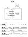
- the lap time pulse starts increasing its pulse duration at time t 0 , as illustrated in Figs. 3A, there is a corresponding amplitude increase at the output of ramp generator 18 to a level exceeding the upper threshold Vh at time t 0 (Figs. 3B, 3C) and the comparator 19 generates a low voltage output (Fig. 3D) which lasts from the occurrence of the abnormal condition to the trailing edge of the lengthened lap time pulse.
- the low level output of the upper threshold comparator 19 causes AND gate 15 to produce a low-level, program execution alarm signal during times t 1 and t 2 (Fig. 3E) and triggers the alarm 16 .
- the CPU 12 changes the logic level of a flag pulse port FP as it executes a flag setup step provided in a significant point of the main routine as well as in the timer interrupt routine of the repeatedly running program.
- the step execution diagnostic circuit 14 comprises an edge detector 23 which responds to each logic reversal at the flag pulse port FP by producing an output pulse.
- a step counter 24 is connected to edge detector 23 for counting the output of edge detector 23 to produce a stepcount signal indicating the number of steps executed by the CPU 12 .
- the CPU 12 executed a program a predetermined number of times, it supplies a stop command to step counter 24 to hold the step count value.
- the output of counter 24 is supplied to a step-count comparator 25 which compares it with a reference count.
- the stop command signal from the CPU 12 is also applied to comparator 25 as an enabling signal to cause it to compare the step-count reached at the time the stop command is issued with the reference count.
- the counter 24 is subsequently supplied with a reset pulse from the CPU 12 to clear its contents for making a subsequent step-count comparison. If the CPU 12 fails to execute all the necessary steps, the step-count fails to match the reference count and the comparator 25 produces a low level, step execution alarm signal.
- a modified embodiment is shown in shown in Fig. 4.
- a CPU monitoring apparatus 31 is provided which is operated on a software-based algorithm to monitor a CPU 32 which repeatedly executes a program and generates lap time pulses in a manner similar to CPU 12 of the previous embodiment.
- the CPU 32 has an output port P1 through which the lap time pulses LTP are supplied to the interrupt port of monitoring apparatus 31 , an output terminal DSo for outputting a data set signal DS to apparatus 31 , an input terminal DRi for receiving therefrom a data receive signal DR, MFD (main flag data) output terminals Do0 ⁇ Do7 for outputting thereto 8-bit main flag data, and a reset input RSi for receiving a reset signal RS from apparatus 31 .
- MFD main flag data
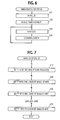
- the main routine of the CPU 32 begins at initialization step 101 , which is followed by step 102 in which the CPU 32 causes a timer interrupt routine to be started.
- step 103 that follows, the CPU 32 executes a main job whose significant steps are shown in Fig. 7.
- the CPU 32 transmits main flag data MFD obtained during the execution of step 104 to the CPU monitoring apparatus 31 and returns to step 103 .
- flag setup steps 210, 220, Vietnamese, 270 are provided in significant points of the main job, and the CPU 32 sets a "1" in the bit positions of eight-bit main flag data MFD, starting at the least significant bit, as it executes each of these flag setup steps. More specifically, when the CPU 32 executes flag setup step 210 , a "1" is set in the least significant bit Mb0 of the main flag data. Likewise, when it executes flag setup step 220 , a "1" is set in the second bit Mb1 of MFD from the least significant position. Thus, when all the flag setup steps are executed, a "1" is set in all of the lower seven positions Mb0 to Mb6 of the 8-bit main flag data. If the CPU 32 fails to execute any one of the flag setup steps, one of the lower significant seven bits of the main flag data remains set to "0".
- the CPU 32 executes communication step 104 .
- the CPU 32 includes a timer, not shown which generates an interrupt pulse at periodic intervals.
- the CPU 32 leaves the main routine and executes an interrupt routine.
- the logic level at the lap time pulse port LTP is changed as shown in Fig. 5A, so that the leading and trailing edges of a lap time pulse occur in step with the timer clock each time an interrupt routine is invoked.
- control checks to see if all bits of an 8-bit interrupt flag data IFD are set to "1".
- the bits lb0, lb1, .., lb7 of this interrupt flag data correspond to flag setup steps 310 , 320 , .... 380 of the interrupt routine, respectively, and each of these bits is set to "1" when the corresponding flag setup step is executed. Therefore, if it is determined that all of the eight bits of interrupt flag data are set to "1", all the steps of the interrupt routine are successfully executed. In this case, the decision at step 302 is affirmative, and control branches to step 303 to set "1" into the most significant bit Mb7 of the main flag data MFD. If at least one of the bits of the IFD data contains a "0", indicating that a portion of the interrupt routine is not executed, control branches at step 302 to step 304 to set a "0" into the most significant bit Mb7 of the MFD data.
- the main flag data MFD becomes all 1's only when all the steps of the interrupt routine are exactly executed, and contains a "0" if any of the steps of the interrupt routine are not executed.
- the 8-bit MFD data indicates whether the flag setup steps 210 ⁇ 270 and 310 ⁇ 380 are all executed or not.
- the main flag data is transmitted to the CPU monitoring apparatus 31 at communication step 104, Fig. 6. Details of communication step 104 are shown at steps 401 ⁇ 402 in Fig. 9.
- the CPU 32 transmits the 8-bit main flag data to the data bus via terminals Do0 ⁇ Do7 as shown in Fig. 5C.
- the CPU 32 drives the data set output terminal DSo to low logic level (active state) at step 402 as shown in Fig. 5B. Since the CPU monitoring apparatus 31 returns a data receive signal DR to the CPU 32 on receiving the main flag data on data input terminals Di0 ⁇ Di7 (see Fig. 5D) in a manner as will be described, control proceeds to decision step 403 to check to see if a data receive signal is returned from the CPU monitoring apparatus 31 .
- the main flag data MFD is transferred from the CPU 32 to the CPU monitoring apparatus 31 according to the prescribed communication procedure when the CPU 32 has repeatedly executed the program a predetermined number of times.
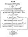
- Fig. 10 shows the main routine executed by the CPU monitoring apparatus 31 .
- the execution of the main routine starts with initialization step 501 , which is followed by step 502 to grant permission to allow a lap time pulse (LTP) interrupt to be executed.
- step 503 the data set terminal DS is checked to see if it is active or not. If the answer is affirmative, control branches at step 503 to step 504 to read the main flag data supplied from the CPU 32 . Exit then is to decision step 505 to determine whether the MFD is all 1's, i.e., whether all the steps of the main and timer interrupt routines are properly executed.
- LTP lap time pulse
- the determination is not based on direct comparison of the step count with the nominal value, but instead the number of bits 1's contained in the main flag data. Since the presence of a "1" in each bit position indicates whether the corresponding step is properly executed, the determination on the basis of the contents of the main flag data is equivalent to the direct comparison of the step count with the nominal value.
- step 506 determines, at step 507 , whether the data set terminal DS is at low logic level (nonactive). If the answer is affirmative, the CPU 32 branches at step 507 to step 508 to render the data receive terminal DR nonactive by switching its logic state to high level, and returns to step 503 , thus completing a communication procedure in cases where there is no abnormal conditions exist in the CPU 32. If the decision at step 505 yields a negative answer, indicating one of the MFD bits is 0, control branches to step 509 to generate a reset signal RS at reset terminal RSo to reset the CPU 32 and activates the alarm 33 at step 510 .
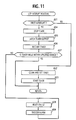
- the CPU monitoring apparatus 31 executes a lap time interrupt routine, shown in Fig. 11, in response to receipt of a lap time pulse LTP from the CPU 32 .
- the lap time interrupt routine begins at decision step 601 to check to see if the execution of the lap time interrupt is the first to perform. If the answer is affirmative, control branches to step 602 to clear and set the timer and then start the timer at step 603 . If the answer is negative at step 601 , control branches to step 604 to stop the timer and latches the contents of the timer at 605 , and then restarts it at step 606 .
- control determines whether the duration of the lap time pulse, as indicated by the latched value of the timer, is within a specified range. If no abnormal condition exists in the CPU 32 , the decision at step 607 yields an affirmative answer and control returns to the main routine. Otherwise, control branches to step 608 to reset the CPU 32 by applying a reset pulse to it via the terminal RSo and activates the alarm 33 at step 609 .
Landscapes
- Engineering & Computer Science (AREA)
- Theoretical Computer Science (AREA)
- Quality & Reliability (AREA)
- Physics & Mathematics (AREA)
- General Engineering & Computer Science (AREA)
- General Physics & Mathematics (AREA)
- Debugging And Monitoring (AREA)
Claims (3)
- Procédé pour contrôler une unité centrale de traitement CPU (12) exécutant de façon répétitive un programme contenant une pluralité d'étapes significatives, ladite unité CPU (12) produisant une impulsion de laps de temps ayant des fronts avant et arrière correspondant respectivement à des exécutions successives dudit programme, une impulsion d'indicateur indiquant qu'une étape significative est exécutée avec succès, et une commande d'arrêt indiquant que ledit programme est exécuté un nombre de fois prédéterminé, le procédé comprenant les étapes de :a) comparaison de la durée de ladite impulsion de laps de temps à une valeur maximale et à une valeur minimale et production d'un signal d'alarme d'exécution de programme quand ladite durée ne se trouve pas entre lesdites valeurs maximale et minimale ;b) comptage de ladite impulsion d'indicateur pour produire un compte d'indicateur et comparaison du compte d'indicateur à une valeur de référence en réponse à ladite commande d'arrêt et production d'un signal d'alarme d'exécution d'étapes si le compte d'indicateur est inférieur à ladite valeur de référence ; et,c) déclenchement d'une alarme en réponse à chacun dudit signal d'alarme d'exécution de programme et dudit signal d'alarme d'exécution d'étapes.
- Procédé pour contrôler une unité centrale de traitement CPU (32) exécutant de façon répétitive un programme contenant une pluralité d'étapes significatives, ladite unité centrale de traitement (32) produisant une impulsion de laps de temps ayant des fronts avant et arrière correspondant respectivement à des exécutions successives dudit programme, et un signal à plusieurs bits dont les positions de bits contiennent un bit à 1 ou un bit à 0 indiquant respectivement si l'unité centrale de traitement a exécuté avec succès ou sans succès chacune desdits étapes significatives, le procédé comprenant les étapes de :a) comparaison de la durée de ladite impulsion de laps de temps à une valeur maximale et à une valeur minimale et production d'un signal d'alarme d'exécution de programme quand ladite durée ne se trouve pas entre lesdites valeurs maximale et minimale ;b) examen du signal à plusieurs bits et production d'un signal d'alarme d'exécution d'étapes si le signal à plusieurs bits contient au moins un bit à 0 ; et,c) déclenchement d'une alarme en réponse à chacun dudit signal d'alarme d'exécution de programme et dudit signal d'alarme d'exécution d'étapes.
- Dispositif pour contrôler une unité centrale de traitement CPU exécutant de façon répétitive un programme contenant une pluralité d'étapes significatives, ladite unité centrale de traitement CPU (32) produisant une impulsion de laps de temps ayant des fronts avant et arrière correspondant respectivement à des exécutions successives dudit programme, et un signal à plusieurs bits dont les positions de bits contiennent un bit à 1 ou un bit à 0 indiquant respectivement si l'unité centrale de traitement a exécuté avec succès ou sans succès chacune desdites étapes significatives, le dispositif (31) étant un dispositif de contrôle à microprocesseur exécutant les fonctions de :a) détermination si ladite impulsion de laps de temps a une durée entre des valeurs maximale et minimale et génération d'un signal d'alarme d'exécution de programme quand ladite durée est déterminée comme n'étant pas entre la valeur maximale et la valeur minimale ;b) réception dudit signal à plusieurs bits provenant de ladite unité CPU (32) ;c) renvoi d'un signal de réception de données à l'unité CPU (32) ;d) production d'un signal d'alarme d'exécution d'étapes si le signal à plusieurs bits reçu contient au moins un bit à 0 ; et,e) fourniture dudit signal d'alarme d'exécution de programme et dudit signal d'alarme d'exécution d'étapes à une unité d'alarme (33).
Applications Claiming Priority (4)
| Application Number | Priority Date | Filing Date | Title |
|---|---|---|---|
| JP26114092 | 1992-09-30 | ||
| JP261140/92 | 1992-09-30 | ||
| JP5149299A JPH06168163A (ja) | 1992-09-30 | 1993-06-21 | Cpu監視方法及びcpu監視装置 |
| JP149299/93 | 1993-06-21 |
Publications (2)
| Publication Number | Publication Date |
|---|---|
| EP0590637A1 EP0590637A1 (fr) | 1994-04-06 |
| EP0590637B1 true EP0590637B1 (fr) | 1998-08-05 |
Family
ID=26479233
Family Applications (1)
| Application Number | Title | Priority Date | Filing Date |
|---|---|---|---|
| EP93115716A Expired - Lifetime EP0590637B1 (fr) | 1992-09-30 | 1993-09-29 | Détection d'opération incorrecte d'unité centrale à partir d'impulsions de laps de temps et du comptage de l'exécution de pas significatifs |
Country Status (5)
| Country | Link |
|---|---|
| US (1) | US5694336A (fr) |
| EP (1) | EP0590637B1 (fr) |
| JP (1) | JPH06168163A (fr) |
| CA (1) | CA2107263C (fr) |
| DE (1) | DE69320132T2 (fr) |
Families Citing this family (12)
| Publication number | Priority date | Publication date | Assignee | Title |
|---|---|---|---|---|
| US8639625B1 (en) * | 1995-02-13 | 2014-01-28 | Intertrust Technologies Corporation | Systems and methods for secure transaction management and electronic rights protection |
| US5892900A (en) * | 1996-08-30 | 1999-04-06 | Intertrust Technologies Corp. | Systems and methods for secure transaction management and electronic rights protection |
| JP3633092B2 (ja) * | 1996-03-18 | 2005-03-30 | 日産自動車株式会社 | マイコン故障監視装置 |
| FI108898B (fi) * | 1996-07-09 | 2002-04-15 | Nokia Corp | Menetelmä prosessorin resetoimiseksi ja vahtikoira |
| US6289400B1 (en) * | 1998-04-15 | 2001-09-11 | Infineon Technologies Ag | Electrical control device with configurable control modules |
| FR2844892B1 (fr) * | 2002-09-24 | 2005-05-27 | St Microelectronics Sa | Horloge de surveillance de microcontroleur |
| US20050188274A1 (en) * | 2004-01-29 | 2005-08-25 | Embedded Wireless Labs | Watchdog system and method for monitoring functionality of a processor |
| JP4983142B2 (ja) | 2006-08-09 | 2012-07-25 | 富士通株式会社 | プログラム監視方法、コンピュータ、および異常監視用プログラム |
| JP5942963B2 (ja) | 2013-11-13 | 2016-06-29 | 株式会社デンソー | マイクロコンピュータの監視装置 |
| JP7095491B2 (ja) | 2018-08-27 | 2022-07-05 | 株式会社デンソー | パルス信号異常検出装置 |
| AU2020307360B2 (en) | 2019-04-25 | 2025-09-25 | Aerovironment, Inc. | Method of flight plan optimization of a high altitude long endurance aircraft |
| WO2020219765A1 (fr) * | 2019-04-25 | 2020-10-29 | Aerovironment, Inc. | Systèmes et procédés de calcul de commande distribuée pour un aéronef haute altitude à grande autonomie |
Family Cites Families (15)
| Publication number | Priority date | Publication date | Assignee | Title |
|---|---|---|---|---|
| US3749897A (en) * | 1971-09-03 | 1973-07-31 | Collins Radio Co | System failure monitor title |
| JPS6032217B2 (ja) * | 1979-04-02 | 1985-07-26 | 日産自動車株式会社 | 制御用コンピュ−タのフェィルセ−フ装置 |
| DE3207633A1 (de) * | 1982-02-26 | 1983-09-15 | Siemens AG, 1000 Berlin und 8000 München | Schaltungsanordnung zur ueberwachung eines mikroprozessors |
| JPS605344A (ja) * | 1983-06-23 | 1985-01-11 | Sogo Jidosha Anzen Kogai Gijutsu Kenkyu Kumiai | 異常検出装置 |
| US4594685A (en) * | 1983-06-24 | 1986-06-10 | General Signal Corporation | Watchdog timer |
| JPS60263235A (ja) * | 1984-06-12 | 1985-12-26 | Omron Tateisi Electronics Co | マイクロコンピユ−タシステム |
| JPS6118045A (ja) * | 1984-07-04 | 1986-01-25 | Fujitsu Ltd | プログラムの暴走検出方式 |
| US4635258A (en) * | 1984-10-22 | 1987-01-06 | Westinghouse Electric Corp. | System for detecting a program execution fault |
| EP0205163B1 (fr) * | 1985-06-11 | 1992-10-28 | Nec Corporation | Circuit de surveillance de temps adapté à l'usage des microcalculateurs |
| US4727549A (en) * | 1985-09-13 | 1988-02-23 | United Technologies Corporation | Watchdog activity monitor (WAM) for use wth high coverage processor self-test |
| US4926427A (en) * | 1986-09-30 | 1990-05-15 | Siemens Aktiengesellschaft | Software error detection apparatus |
| GB2197507A (en) * | 1986-11-03 | 1988-05-18 | Philips Electronic Associated | Data processing system |
| US5245638A (en) * | 1990-10-29 | 1993-09-14 | Iowa State University Research Foundation, Inc. | Method and system for benchmarking computers |
| GB9023633D0 (en) * | 1990-10-31 | 1990-12-12 | Int Computers Ltd | Predicting the performance of a computer system |
| US5303166A (en) * | 1992-04-14 | 1994-04-12 | International Business Machines Corporation | Method and system for automated network benchmark performance analysis |
-
1993
- 1993-06-21 JP JP5149299A patent/JPH06168163A/ja active Pending
- 1993-09-29 CA CA002107263A patent/CA2107263C/fr not_active Expired - Lifetime
- 1993-09-29 EP EP93115716A patent/EP0590637B1/fr not_active Expired - Lifetime
- 1993-09-29 DE DE69320132T patent/DE69320132T2/de not_active Expired - Lifetime
-
1996
- 1996-05-03 US US08/642,668 patent/US5694336A/en not_active Expired - Lifetime
Also Published As
| Publication number | Publication date |
|---|---|
| EP0590637A1 (fr) | 1994-04-06 |
| DE69320132T2 (de) | 1998-12-10 |
| CA2107263A1 (fr) | 1994-03-31 |
| US5694336A (en) | 1997-12-02 |
| CA2107263C (fr) | 1999-04-06 |
| JPH06168163A (ja) | 1994-06-14 |
| DE69320132D1 (de) | 1998-09-10 |
Similar Documents
| Publication | Publication Date | Title |
|---|---|---|
| US4956842A (en) | Diagnostic system for a watchdog timer | |
| US4405982A (en) | Arrangement for monitoring the function of a programmable electronic switching circuit | |
| US4683568A (en) | Method of monitoring computer elements, particularly microprocessors | |
| US8909971B2 (en) | Clock supervision unit | |
| US5694336A (en) | Detection of improper CPU operation from lap time pulses and count of executed significant steps | |
| US4875209A (en) | Transient and intermittent fault insertion | |
| US3934131A (en) | Output controller for initiating delayed or conditional commands via a general purpose computer | |
| US6076172A (en) | Monitoting system for electronic control unit | |
| US5740360A (en) | Apparatus and method for resetting a microprocessor in the event of improper program execution | |
| US3749897A (en) | System failure monitor title | |
| US6694452B1 (en) | Data processor and method of processing data | |
| JP2593915B2 (ja) | ダブルマイコンシステム暴走防止回路 | |
| US20020114409A1 (en) | Serial data communication apparatus and detection method for communication error | |
| US4698829A (en) | Monitoring system for verifying that an input signal is toggling at a minimum frequency | |
| EP0788227B1 (fr) | Commutateur de temps | |
| US5673389A (en) | Methods and apparatus for resetting a monitored system using a gray code with alternating check bits | |
| US4710928A (en) | Method and apparatus for detecting the uncontrollable operation of a control system | |
| EP0430843B1 (fr) | Méthode et dispositif pour tester les fautes de bus d'adresses, de données et de contrÔle d'un microprocesseur | |
| JP2659067B2 (ja) | マイクロコンピュータのリセット回路 | |
| JP3440350B2 (ja) | 通信装置 | |
| JPH04283840A (ja) | 情報処理装置の診断方法 | |
| KR20070012351A (ko) | 전자 회로 장치 및 이 전자 회로 장치를 사전결정된 상태에이르게 하는 방법 | |
| CN120597803A (zh) | 时钟监控装置 | |
| SU1048578A1 (ru) | Устройство дл контрол источников сигналов | |
| SU1088001A1 (ru) | Устройство дл контрол цепей управлени операци ми |
Legal Events
| Date | Code | Title | Description |
|---|---|---|---|
| PUAI | Public reference made under article 153(3) epc to a published international application that has entered the european phase |
Free format text: ORIGINAL CODE: 0009012 |
|
| AK | Designated contracting states |
Kind code of ref document: A1 Designated state(s): DE FR GB |
|
| 17P | Request for examination filed |
Effective date: 19940209 |
|
| 17Q | First examination report despatched |
Effective date: 19960319 |
|
| GRAG | Despatch of communication of intention to grant |
Free format text: ORIGINAL CODE: EPIDOS AGRA |
|
| GRAG | Despatch of communication of intention to grant |
Free format text: ORIGINAL CODE: EPIDOS AGRA |
|
| GRAG | Despatch of communication of intention to grant |
Free format text: ORIGINAL CODE: EPIDOS AGRA |
|
| GRAH | Despatch of communication of intention to grant a patent |
Free format text: ORIGINAL CODE: EPIDOS IGRA |
|
| GRAH | Despatch of communication of intention to grant a patent |
Free format text: ORIGINAL CODE: EPIDOS IGRA |
|
| GRAA | (expected) grant |
Free format text: ORIGINAL CODE: 0009210 |
|
| AK | Designated contracting states |
Kind code of ref document: B1 Designated state(s): DE FR GB |
|
| REF | Corresponds to: |
Ref document number: 69320132 Country of ref document: DE Date of ref document: 19980910 |
|
| ET | Fr: translation filed | ||
| PLBE | No opposition filed within time limit |
Free format text: ORIGINAL CODE: 0009261 |
|
| STAA | Information on the status of an ep patent application or granted ep patent |
Free format text: STATUS: NO OPPOSITION FILED WITHIN TIME LIMIT |
|
| 26N | No opposition filed | ||
| REG | Reference to a national code |
Ref country code: GB Ref legal event code: IF02 |
|
| REG | Reference to a national code |
Ref country code: GB Ref legal event code: 732E |
|
| REG | Reference to a national code |
Ref country code: FR Ref legal event code: TP |
|
| PGFP | Annual fee paid to national office [announced via postgrant information from national office to epo] |
Ref country code: GB Payment date: 20120926 Year of fee payment: 20 |
|
| PGFP | Annual fee paid to national office [announced via postgrant information from national office to epo] |
Ref country code: DE Payment date: 20120927 Year of fee payment: 20 Ref country code: FR Payment date: 20120926 Year of fee payment: 20 |
|
| REG | Reference to a national code |
Ref country code: DE Ref legal event code: R071 Ref document number: 69320132 Country of ref document: DE |
|
| REG | Reference to a national code |
Ref country code: GB Ref legal event code: PE20 Expiry date: 20130928 |
|
| PG25 | Lapsed in a contracting state [announced via postgrant information from national office to epo] |
Ref country code: GB Free format text: LAPSE BECAUSE OF EXPIRATION OF PROTECTION Effective date: 20130928 |
|
| PG25 | Lapsed in a contracting state [announced via postgrant information from national office to epo] |
Ref country code: DE Free format text: LAPSE BECAUSE OF EXPIRATION OF PROTECTION Effective date: 20131001 |