EP0590810B1 - Differentialleitungsfähigkeitsrückströmungsmonitor - Google Patents
Differentialleitungsfähigkeitsrückströmungsmonitor Download PDFInfo
- Publication number
- EP0590810B1 EP0590810B1 EP93307033A EP93307033A EP0590810B1 EP 0590810 B1 EP0590810 B1 EP 0590810B1 EP 93307033 A EP93307033 A EP 93307033A EP 93307033 A EP93307033 A EP 93307033A EP 0590810 B1 EP0590810 B1 EP 0590810B1
- Authority
- EP
- European Patent Office
- Prior art keywords
- conductivity
- fluid
- conductivity cell
- electrical
- cell
- Prior art date
- Legal status (The legal status is an assumption and is not a legal conclusion. Google has not performed a legal analysis and makes no representation as to the accuracy of the status listed.)
- Expired - Lifetime
Links
- 239000012530 fluid Substances 0.000 claims description 120
- 210000004369 blood Anatomy 0.000 claims description 91
- 239000008280 blood Substances 0.000 claims description 91
- 238000000034 method Methods 0.000 claims description 25
- 238000012545 processing Methods 0.000 claims description 23
- 238000011144 upstream manufacturing Methods 0.000 claims description 21
- 238000012360 testing method Methods 0.000 claims description 18
- 239000003550 marker Substances 0.000 claims description 8
- 238000001631 haemodialysis Methods 0.000 claims description 6
- 230000001939 inductive effect Effects 0.000 claims description 6
- 206010003226 Arteriovenous fistula Diseases 0.000 claims description 5
- 230000000694 effects Effects 0.000 claims description 3
- 239000000076 hypertonic saline solution Substances 0.000 claims description 3
- 230000000007 visual effect Effects 0.000 claims description 3
- 238000004891 communication Methods 0.000 claims description 2
- 230000001419 dependent effect Effects 0.000 claims description 2
- 238000003780 insertion Methods 0.000 claims 1
- 230000037431 insertion Effects 0.000 claims 1
- 210000004027 cell Anatomy 0.000 description 104
- 206010016717 Fistula Diseases 0.000 description 25
- 230000003890 fistula Effects 0.000 description 25
- 238000000502 dialysis Methods 0.000 description 23
- 230000005284 excitation Effects 0.000 description 19
- 238000005259 measurement Methods 0.000 description 6
- 210000001367 artery Anatomy 0.000 description 4
- 230000007423 decrease Effects 0.000 description 4
- 210000003462 vein Anatomy 0.000 description 4
- 230000017531 blood circulation Effects 0.000 description 3
- 230000004087 circulation Effects 0.000 description 3
- 238000010586 diagram Methods 0.000 description 3
- 238000007373 indentation Methods 0.000 description 3
- 230000003287 optical effect Effects 0.000 description 3
- 230000003134 recirculating effect Effects 0.000 description 3
- 230000008901 benefit Effects 0.000 description 2
- DDRJAANPRJIHGJ-UHFFFAOYSA-N creatinine Chemical compound CN1CC(=O)NC1=N DDRJAANPRJIHGJ-UHFFFAOYSA-N 0.000 description 2
- 230000000322 hemodialysis Effects 0.000 description 2
- 239000007788 liquid Substances 0.000 description 2
- 239000012528 membrane Substances 0.000 description 2
- 230000001225 therapeutic effect Effects 0.000 description 2
- XSQUKJJJFZCRTK-UHFFFAOYSA-N Urea Chemical compound NC(N)=O XSQUKJJJFZCRTK-UHFFFAOYSA-N 0.000 description 1
- PNNCWTXUWKENPE-UHFFFAOYSA-N [N].NC(N)=O Chemical compound [N].NC(N)=O PNNCWTXUWKENPE-UHFFFAOYSA-N 0.000 description 1
- 230000009471 action Effects 0.000 description 1
- 210000001557 animal structure Anatomy 0.000 description 1
- 210000000601 blood cell Anatomy 0.000 description 1
- 238000004422 calculation algorithm Methods 0.000 description 1
- 238000004364 calculation method Methods 0.000 description 1
- 239000004202 carbamide Substances 0.000 description 1
- 230000000747 cardiac effect Effects 0.000 description 1
- 230000008859 change Effects 0.000 description 1
- 230000008878 coupling Effects 0.000 description 1
- 238000010168 coupling process Methods 0.000 description 1
- 238000005859 coupling reaction Methods 0.000 description 1
- 229940109239 creatinine Drugs 0.000 description 1
- 238000012864 cross contamination Methods 0.000 description 1
- 238000002405 diagnostic procedure Methods 0.000 description 1
- 239000012535 impurity Substances 0.000 description 1
- 208000015181 infectious disease Diseases 0.000 description 1
- 230000000977 initiatory effect Effects 0.000 description 1
- 239000004973 liquid crystal related substance Substances 0.000 description 1
- 230000013011 mating Effects 0.000 description 1
- 230000002572 peristaltic effect Effects 0.000 description 1
- 235000012434 pretzels Nutrition 0.000 description 1
- 238000011160 research Methods 0.000 description 1
- 238000002560 therapeutic procedure Methods 0.000 description 1
- 238000012546 transfer Methods 0.000 description 1
Images



Classifications
-
- G—PHYSICS
- G01—MEASURING; TESTING
- G01F—MEASURING VOLUME, VOLUME FLOW, MASS FLOW OR LIQUID LEVEL; METERING BY VOLUME
- G01F1/00—Measuring the volume flow or mass flow of fluid or fluent solid material wherein the fluid passes through a meter in a continuous flow
- G01F1/704—Measuring the volume flow or mass flow of fluid or fluent solid material wherein the fluid passes through a meter in a continuous flow using marked regions or existing inhomogeneities within the fluid stream, e.g. statistically occurring variations in a fluid parameter
- G01F1/708—Measuring the time taken to traverse a fixed distance
- G01F1/7088—Measuring the time taken to traverse a fixed distance using electrically charged particles as tracers
-
- A—HUMAN NECESSITIES
- A61—MEDICAL OR VETERINARY SCIENCE; HYGIENE
- A61M—DEVICES FOR INTRODUCING MEDIA INTO, OR ONTO, THE BODY; DEVICES FOR TRANSDUCING BODY MEDIA OR FOR TAKING MEDIA FROM THE BODY; DEVICES FOR PRODUCING OR ENDING SLEEP OR STUPOR
- A61M1/00—Suction or pumping devices for medical purposes; Devices for carrying-off, for treatment of, or for carrying-over, body-liquids; Drainage systems
- A61M1/14—Dialysis systems; Artificial kidneys; Blood oxygenators ; Reciprocating systems for treatment of body fluids, e.g. single needle systems for hemofiltration or pheresis
- A61M1/16—Dialysis systems; Artificial kidneys; Blood oxygenators ; Reciprocating systems for treatment of body fluids, e.g. single needle systems for hemofiltration or pheresis with membranes
-
- A—HUMAN NECESSITIES
- A61—MEDICAL OR VETERINARY SCIENCE; HYGIENE
- A61M—DEVICES FOR INTRODUCING MEDIA INTO, OR ONTO, THE BODY; DEVICES FOR TRANSDUCING BODY MEDIA OR FOR TAKING MEDIA FROM THE BODY; DEVICES FOR PRODUCING OR ENDING SLEEP OR STUPOR
- A61M1/00—Suction or pumping devices for medical purposes; Devices for carrying-off, for treatment of, or for carrying-over, body-liquids; Drainage systems
- A61M1/36—Other treatment of blood in a by-pass of the natural circulatory system, e.g. temperature adaptation, irradiation ; Extra-corporeal blood circuits
- A61M1/3607—Regulation parameters
- A61M1/3609—Physical characteristics of the blood, e.g. haematocrit, urea
- A61M1/361—Physical characteristics of the blood, e.g. haematocrit, urea before treatment
-
- A—HUMAN NECESSITIES
- A61—MEDICAL OR VETERINARY SCIENCE; HYGIENE
- A61M—DEVICES FOR INTRODUCING MEDIA INTO, OR ONTO, THE BODY; DEVICES FOR TRANSDUCING BODY MEDIA OR FOR TAKING MEDIA FROM THE BODY; DEVICES FOR PRODUCING OR ENDING SLEEP OR STUPOR
- A61M1/00—Suction or pumping devices for medical purposes; Devices for carrying-off, for treatment of, or for carrying-over, body-liquids; Drainage systems
- A61M1/36—Other treatment of blood in a by-pass of the natural circulatory system, e.g. temperature adaptation, irradiation ; Extra-corporeal blood circuits
- A61M1/3607—Regulation parameters
- A61M1/3609—Physical characteristics of the blood, e.g. haematocrit, urea
- A61M1/3612—Physical characteristics of the blood, e.g. haematocrit, urea after treatment
-
- A—HUMAN NECESSITIES
- A61—MEDICAL OR VETERINARY SCIENCE; HYGIENE
- A61M—DEVICES FOR INTRODUCING MEDIA INTO, OR ONTO, THE BODY; DEVICES FOR TRANSDUCING BODY MEDIA OR FOR TAKING MEDIA FROM THE BODY; DEVICES FOR PRODUCING OR ENDING SLEEP OR STUPOR
- A61M1/00—Suction or pumping devices for medical purposes; Devices for carrying-off, for treatment of, or for carrying-over, body-liquids; Drainage systems
- A61M1/36—Other treatment of blood in a by-pass of the natural circulatory system, e.g. temperature adaptation, irradiation ; Extra-corporeal blood circuits
- A61M1/3621—Extra-corporeal blood circuits
- A61M1/3653—Interfaces between patient blood circulation and extra-corporal blood circuit
-
- A—HUMAN NECESSITIES
- A61—MEDICAL OR VETERINARY SCIENCE; HYGIENE
- A61M—DEVICES FOR INTRODUCING MEDIA INTO, OR ONTO, THE BODY; DEVICES FOR TRANSDUCING BODY MEDIA OR FOR TAKING MEDIA FROM THE BODY; DEVICES FOR PRODUCING OR ENDING SLEEP OR STUPOR
- A61M1/00—Suction or pumping devices for medical purposes; Devices for carrying-off, for treatment of, or for carrying-over, body-liquids; Drainage systems
- A61M1/36—Other treatment of blood in a by-pass of the natural circulatory system, e.g. temperature adaptation, irradiation ; Extra-corporeal blood circuits
- A61M1/3621—Extra-corporeal blood circuits
- A61M1/3653—Interfaces between patient blood circulation and extra-corporal blood circuit
- A61M1/3655—Arterio-venous shunts or fistulae
-
- A—HUMAN NECESSITIES
- A61—MEDICAL OR VETERINARY SCIENCE; HYGIENE
- A61M—DEVICES FOR INTRODUCING MEDIA INTO, OR ONTO, THE BODY; DEVICES FOR TRANSDUCING BODY MEDIA OR FOR TAKING MEDIA FROM THE BODY; DEVICES FOR PRODUCING OR ENDING SLEEP OR STUPOR
- A61M1/00—Suction or pumping devices for medical purposes; Devices for carrying-off, for treatment of, or for carrying-over, body-liquids; Drainage systems
- A61M1/36—Other treatment of blood in a by-pass of the natural circulatory system, e.g. temperature adaptation, irradiation ; Extra-corporeal blood circuits
- A61M1/3621—Extra-corporeal blood circuits
- A61M1/3653—Interfaces between patient blood circulation and extra-corporal blood circuit
- A61M1/3656—Monitoring patency or flow at connection sites; Detecting disconnections
- A61M1/3658—Indicating the amount of purified blood recirculating in the fistula or shunt
-
- A—HUMAN NECESSITIES
- A61—MEDICAL OR VETERINARY SCIENCE; HYGIENE
- A61M—DEVICES FOR INTRODUCING MEDIA INTO, OR ONTO, THE BODY; DEVICES FOR TRANSDUCING BODY MEDIA OR FOR TAKING MEDIA FROM THE BODY; DEVICES FOR PRODUCING OR ENDING SLEEP OR STUPOR
- A61M1/00—Suction or pumping devices for medical purposes; Devices for carrying-off, for treatment of, or for carrying-over, body-liquids; Drainage systems
- A61M1/36—Other treatment of blood in a by-pass of the natural circulatory system, e.g. temperature adaptation, irradiation ; Extra-corporeal blood circuits
- A61M1/3621—Extra-corporeal blood circuits
- A61M1/3669—Electrical impedance measurement of body fluids; transducers specially adapted therefor
-
- G—PHYSICS
- G01—MEASURING; TESTING
- G01F—MEASURING VOLUME, VOLUME FLOW, MASS FLOW OR LIQUID LEVEL; METERING BY VOLUME
- G01F1/00—Measuring the volume flow or mass flow of fluid or fluent solid material wherein the fluid passes through a meter in a continuous flow
- G01F1/704—Measuring the volume flow or mass flow of fluid or fluent solid material wherein the fluid passes through a meter in a continuous flow using marked regions or existing inhomogeneities within the fluid stream, e.g. statistically occurring variations in a fluid parameter
- G01F1/7046—Measuring the volume flow or mass flow of fluid or fluent solid material wherein the fluid passes through a meter in a continuous flow using marked regions or existing inhomogeneities within the fluid stream, e.g. statistically occurring variations in a fluid parameter using electrical loaded particles as tracer, e.g. ions or electrons
-
- G—PHYSICS
- G01—MEASURING; TESTING
- G01F—MEASURING VOLUME, VOLUME FLOW, MASS FLOW OR LIQUID LEVEL; METERING BY VOLUME
- G01F1/00—Measuring the volume flow or mass flow of fluid or fluent solid material wherein the fluid passes through a meter in a continuous flow
- G01F1/704—Measuring the volume flow or mass flow of fluid or fluent solid material wherein the fluid passes through a meter in a continuous flow using marked regions or existing inhomogeneities within the fluid stream, e.g. statistically occurring variations in a fluid parameter
- G01F1/708—Measuring the time taken to traverse a fixed distance
-
- A—HUMAN NECESSITIES
- A61—MEDICAL OR VETERINARY SCIENCE; HYGIENE
- A61M—DEVICES FOR INTRODUCING MEDIA INTO, OR ONTO, THE BODY; DEVICES FOR TRANSDUCING BODY MEDIA OR FOR TAKING MEDIA FROM THE BODY; DEVICES FOR PRODUCING OR ENDING SLEEP OR STUPOR
- A61M1/00—Suction or pumping devices for medical purposes; Devices for carrying-off, for treatment of, or for carrying-over, body-liquids; Drainage systems
- A61M1/36—Other treatment of blood in a by-pass of the natural circulatory system, e.g. temperature adaptation, irradiation ; Extra-corporeal blood circuits
- A61M1/3601—Extra-corporeal circuits in which the blood fluid passes more than once through the treatment unit
- A61M1/3603—Extra-corporeal circuits in which the blood fluid passes more than once through the treatment unit in the same direction
Definitions
- This invention relates to measurement of recirculation efficiency. More particularly, this invention relates to measurement of the recirculation efficiency of a biological or medical fluid during a medical procedure or for diagnostic purposes.
- hemodialysis (herein “dialysis”) is an inconvenient, expensive, and uncomfortable medical procedure. It is, therefore, widely recognized as desirable to minimize the amount of time required to complete the procedure and to achieve a desired level of treatment.
- a joint In dialysis, a joint is typically surgically created between a vein and an artery of a patient undergoing dialysis.
- the joint provides a blood access site where an inlet line to a dialysis apparatus and an outlet line from the dialysis apparatus are connected.
- the inlet line draws blood to be treated from the patient, while the outlet line returns treated blood to the patient.
- This joint may be an arteriovenous fistula, which is a direct connection of one of the patient's veins to one of the patient's arteries.
- the joint may be a synthetic or animal organ graft connecting the vein to the artery.
- the term "fistula" refers to any surgically created or implanted joint between one of the patient's veins and one of the patient's arteries, however created.
- a portion of the treated blood returned to the patient by the outlet line may recirculate.
- Recirculating treated blood will co-mingle with untreated blood being withdrawn from the patient by the inlet line.
- This recirculation, and the resulting co-mingling of treated and untreated blood is dependent, in part, on the rate at which blood is withdrawn from and returned to the patient.
- the relationship is typically a direct, but non-linear relationship. It can be readily appreciated that the dialysis apparatus will operate most effectively, and the desired level of treatment achieved in the shortest period of time, when the inlet line is drawing only untreated blood at the maximum flow rate capability of the dialysis apparatus consistent with patient safety.
- the proportion of recirculated treated blood in the blood being drawn through the inlet line is increased.
- a method and apparatus for qualitatively detecting the presence or absence of recirculation in a fistula is described in "FAM 10 Fistula Flow Studies and their Interpretation” published by Gambro, Ltd. based on research performed in 1982.
- the Gambro method and apparatus injects a quantity of a fluid having an optical density less than the optical density of treated blood into the dialysis apparatus outlet line.
- a resulting change in the optical density of the blood being drawn through the dialysis apparatus inlet line is qualitatively detected as indicative of the presence of recirculation.
- the Gambro method and apparatus does not quantitatively determine or measure a recirculation ratio or recirculation efficiency.
- a quantitative measurement of the recirculation efficiency of a bodily or medical fluid is useful in other therapeutic and diagnostic procedures as well.
- recirculation ratios and efficiencies are useful for determining cardiac output, intervascular recirculation, recirculation in non-surgically created access sites, and dialyzer performance from either the blood side of the dialysate side of the dialyzer, or both.
- European Patent No. 0 272 414 to Fresenius AG discloses measurement of the values of the conductivity of blood entering and leaving a fistula and computing a difference between said values.
- a significant aspect of the present invention is a method for determining a difference between the electrical conductivities of two fluids, comprising the steps of:
- Another significant aspect of the present invention is a method for quantitively determining a degree of recirculation flow in a zone of a vessel into which a first fluid having a first electrical conductivity is being inserted and from which a fluid having a second electrical conductivity is simultaneously being withdrawn, employing the above described method for determining the difference in the electrical conductivities of two fluids, and also altering the electrical conductivity of the first fluid prior to the first current being induced in that first fluid in the first conductivity cell.
- the step of altering the electrical conductivity of the first fluid may comprise injecting a marker fluid having an electrical conductivity different from the conductivity of the first fluid into the first fluid.
- the zone of the vessel may be a surgically formed arteriovenous fistula; the first conductivity cell may be positioned in a conduit which is an outlet line of a medical device for blood processing; the second conductivity cell may be positioned in a conduit that is an inlet line of the medical device for blood processing; the first fluid may be blood processed by the medical device for blood processing; and the second fluid may be blood to be processed by the medical device for blood processing.
- the medical device for blood processing may be a haemodialysis device.
- Another significant aspect of the present invention is an apparatus for determining a difference between the electrical conductivities of two fluids comprising a first conductivity cell for measuring the conductivity of a first fluid and a second conductivity cell for measuring the conductivity of a second fluid; characterized in that
- Another significant aspect of the present invention is an apparatus for quantitively determining a degree of recirculation flow in a zone of a vessel into which a first fluid having a first electrical conductivity is being inserted and from which a fluid having second electrical conductivity is simultaneously being withdrawn, comprising the above described apparatus for determining a difference in the electrical conductivities of two fluids and also means for altering the electrical conductivity of the first fluid before, in use, the first current is induced in that first fluid in the first conductivity cell.
- the means for altering the electrical conductivity of the first fluid may comprise means for injecting a marker fluid having an electrical conductivity different from the conductivity of the first fluid into the first fluid.
- the zone of the vessel may be a surgically formed arteriovenous fistula;
- the first conductivity cell may be positioned in a conduit which is an outlet line of a medical device for blood processing;
- the second conductivity cell may be positioned in a conduit that is an inlet line of the medical device for blood processing;
- the first fluid may be blood processed by the medical device for blood processing;
- the second fluid may be blood to be processed by the medical device for blood processing.
- the medical device for blood processing may be a haemodialysis device.
- a tubing set adapted for use in an apparatus for determining a degree of recirculation flow in a zone of a vessel as described above, comprising the first conductivity cell and the second conductivity cell; wherein the first conductivity cell is adjacent to the second conductivity cell at a first abutment in a generally parallel relationship.
- the first conductivity cell may be adjacent to the second conductivity cell at a second abutment in a generally angular relationship.
- the tubing set may comprise a hypodermic needle access site in fluid communication with the first conductivity cell.
- Fig. 1 is a schematic diagram of a dialysis system incorporating a differential conductivity recirculation monitor in accordance with the present invention.
- Fig. 2 is a partial perspective view illustrating the functional elements of the differential conductivity recirculation monitor shown in Fig. 1.
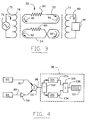
- Fig. 3 is an electrical schematic diagram of the differential conductivity recirculation monitor shown in Fig. 2.
- Fig. 4 is an electrical block diagram of sensing logic usable with the differential conductivity recirculation monitor illustrated in Figs. 2 and 3.
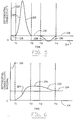
- Fig. 5 is a graph illustrating differential conductivity versus time during a recirculation test employing the differential conductivity recirculation monitor shown in Fig. 2.
- Fig. 6 is a graph illustrating the integral of differential conductivity versus time during a recirculation test employing the differential conductivity recirculation monitor shown in Fig. 2, having substantially the same time scale as Fig. 5.
- Fig. 7 is a partial elevational view of a tubing set and sectional view of an excitation and sensing unit for use with the dialysis system shown in Fig. 1, incorporating the differential conductivity recirculation monitor in accordance with the present invention.
- Fig. 8 is a partially diagrammatic sectional view taken substantially at line 8-8 in Fig. 7.
- Fig. 9 is a partially diagrammatic perspective view of the excitation and sensing unit of the differential conductivity recirculation monitor of the present invention.
- Fig. 1 illustrates a dialysis system 20 incorporating a differential conductivity recirculation monitor 22 for determining and displaying recirculation efficiency in accordance with the present invention.
- the dialysis system 20 which is one example of a medical system with which the present invention may be advantageously used, comprises a dialysis apparatus 24 connected to a fistula 26 surgically formed in a dialysis patient (not shown). Untreated blood is drawn from the fistula 26 through a dialyzer inlet needle 28 and a dialyzer inlet line 30. Treated blood is returned to the fistula through a dialyzer outlet line 32 and a dialyzer outlet needle 34.
- the recirculation monitor 22 is located in the dialyzer inlet and outlet lines 30 and 32 at a point intermediate between the fistula 26 and the dialysis apparatus 24.
- the dialysis apparatus 24 comprises a blood pump 36 typically a peristaltic pump, a dialyzer 38 having a blood compartment 40 and a dialysate compartment 42 separated by a semi-permeable membrane 44, a bubble trap 46 and a dialysate generator 48.
- Blood is drawn from the fistula 26 by the action of the blood pump 36 and passed through the blood compartment 40 of the dialyzer 38.
- the membrane 44 allows transfer of impurities in the blood, such as urea and creatinine, from the blood compartment 40 to the dialysate compartment 42 of the dialyzer 38.
- the dialysate compartment 42 is connected to a dialysate generator 48 which generates the dialysate, a liquid isotonic to blood, and circulates it through the dialysate compartment 42.
- the recirculation detector 22 comprises a needle access site 50 in the dialyzer outlet line 32.
- a first or outlet conductivity cell 52 is located in the dialyser outlet line 32 downstream of the needle access site 50.
- a second or inlet conductivity cell 54 is located in the dialyzer inlet line 30.
- the first conductivity cell 52 comprises an upstream connection 56, a downstream connection 58 and first and second tubing branches 60 and 62, respectively, each of which interconnect the upstream connection 56 with the downstream connection 58.
- Treated blood from the dialyzer flows in the dialyzer outlet line 32 through the needle access site 50 to the upstream connection 56.
- the inlet conductivity cell 54 comprises an upstream connection 64, a downstream connection 66 and third and fourth tubing branches 68 and 70, respectively, which each connect the upstream connection 64 to the downstream connection 66.
- Each one of the tubing branches 60, 62, 68 and 70 has the same cross sectional area and length as each other one of the tubing branches.
- the blood, or other biological or medical fluid, flowing in each conductivity cell 52 and 54 comprises an electrical circuit.
- the electrical circuit is a path for circulation of an electrical current from the upstream connection, through one of the tubing branches, to the downstream connection and from the downstream connection through the other one of the tubing branches to the upstream connection.
- the outlet conductivity cell 52 and the inlet conductivity cell 54 are positioned adjacent to each other in an angular relationship resembling a pretzel so that the first tubing branch 60 of the outlet conductivity cell 52 is positioned parallel to the third tubing branch 68 of the inlet conductivity cell at an excitation location.
- the conductivity cells are further positioned so that the second tubing branch 62 of the outlet conductivity cell 52 crosses the fourth tubing branch 70 of the inlet conductivity cell 54 at an angle, approximately sixty degrees in the preferred embodiment, at a sensing location.
- An excitation coil 72 encircles the first tubing branch 60 of the outlet conductivity cell 52 and the third tubing branch 68 of the inlet conductivity cell 54 at the excitation location.
- a sensing coil 74 encircles the second tubing branch 62 of the outlet conductivity cell 52 and the fourth tubing branch 70 of the inlet conductivity cell 54 at the sensing location.
- the excitation coil 72 is inductively coupled to the outlet conductivity cell 52 and the inlet conductivity cell 54.
- a source of excitation energy 76 causes an alternating excitation current, illustrated by direction arrow 78, to flow in the excitation coil 72 a changing magnetic field is generated which causes an electrical current, illustrated by the direction arrow 80, to flow in the blood in the outlet conductivity cell 52 and causes another electrical current, illustrated by direction arrow 82, to flow in the same electrical direction in the blood in the inlet conductivity cell 54.
- the conductivity cells 52 and 54 are formed to create electrical paths of equal cross sectional area and equal path length the electrical conductance of the paths, as illustrated by the schematic resistors 84 and 86, and thus the magnitude of the induced currents 80 and 82, will be related to the conductivity of the blood in the respective conductivity cells 52 and 54.
- the induced currents 80 and 82 flowing in the outlet and inlet conductivity cells 52 and 54 generate a changing magnetic field at the sensing location that induces a sensed current, illustrated by direction arrow 88, in the sensing coil 74.
- the induced currents 80 and 82 are in opposite electrical directions so that the magnetic field at the sensing location has a magnitude proportional to the difference between the induced currents.
- the sensed current 88 is proportional to the magnetic field at the sensing location where the sensing coil 74 encircles the second and fourth tubing branches 62 and 70, respectively.
- the sensed current 88 induced in the sensing transformer 74 is therefore proportional to a difference between the induced currents 80 and 82 in the outlet and inlet conductivity cells 52 and 54, respectively.
- the induced currents 80 and 82 in the outlet and inlet conductivity cells 52 and 54, respectively, are related to the conductivity of the fluids in those chambers. Therefore, the magnitude of the sensed current 88 induced in the sensing coil 74 will be related to the difference between the conductivities of the fluids in the outlet and inlet conductivity cells 52 and 54.
- the sensed current 88 is delivered to, and interpreted by a sensing logic and display circuit 90, which displays the recirculation efficiency.
- the dialysis system operator injects a bolus of a marker fluid into the treated blood in the dialyzer outlet line 32 at the needle access site 50 using a typical hypodermic needle 92.
- the marker fluid may have an electrical conductivity that is higher or lower than the fluid flowing in the outlet line 32.
- a high conductivity marker fluid is used to avoid damaging blood cells.
- the bolus is 1 milliliter of 24 percent hypertonic saline solution.
- the conductivity of the treated blood being returned to the patient through the dialyzer outlet line 32 and the outlet conductivity cell 52 of the recirculation monitor 22 is altered. This altered conductivity blood enters the fistula through the outlet needle 34.
- the flow balance in the fistula 26 is such that no flow is recirculating the altered conductivity blood will exit the fistula, as illustrated by the flow circulation arrow 94, without altering the conductivity of the blood within the fistula. If, however, the flow balance within the fistula 26 is such that blood is recirculating, as illustrated by flow circulation arrow 96, a portion of the blood withdrawn from the fistula 26 by the pump 36 will be the altered conductivity blood.
- the recirculation monitor 22 measures the conductivity of the blood flowing in the outlet line 32 and the conductivity of the blood flowing in the inlet line 30 and quantitatively determines the difference between those conductivities continuously throughout the recirculation test.
- the sensing logic and display circuit 90 interprets the quantitative conductivity differences measured by the recirculation monitor 22 to determine recirculation efficiency.
- the outlet conductivity cell 52 and the inlet conductivity cell 54 may be thought of as signal generators generating the induced currents 80 and 82 in the outlet and inlet conductivity cells.
- the induced current 82 of the inlet conductivity cell 54 is inverted 98 and added 100 to the induced current 80 in the outlet conductivity cell 52, by virtue of the physical relationships between the conductivity cells, excitation coil 72 and sensing coil 74, to produce the sensed current 88.
- the sensing logic and display circuit 90 performs a zeroing operation 102, a dialyzer outlet flow determining operation 104, and unrecirculated flow determining operation 106, and a dividing operation 108, and includes a visual display device 110, preferably a liquid crystal display.
- a digital computer not shown.
- Fig. 5 is a graph illustrating differential conductivity (reference 112) as a function of time (reference 114) during a typical recirculation test.
- Fig. 6 is a graph illustrating the integral of differential conductivity (reference 116) as a function of time 114 during the typical recirculation test.
- Reference 118 Prior to the beginning of the recirculation test there may be some normal difference (reference 118) between the conductivity of the treated blood in the dialyzer outlet line 32 (Fig. 2) and the untreated blood in the dialyzer inlet line 30 (Fig. 2).
- This normal conductivity difference 118 is subtracted from the sensed current 88 by the zeroing operation 102 of the sensing logic and display circuit 90 to remove the effect of the normal difference in conductivity 118 from determination of recirculation efficiency.
- the recirculation test begins (reference time T1) when the bolus of high conductivity fluid is injected into the dialyzer outlet line 32 (Fig. 2) at the needle access site 50 (Fig. 2). The conductivity of the treated blood in the dialyzer outlet line 32 (Fig. 2) is increased. As the bolus passes through the outlet conductivity cell 52 (Fig. 2) the differential conductivity 112 increases (reference 120) and then decreases (reference 122) until the normal conductivity difference 118 is reached (reference time T2).
- the outlet flow determining operation 104 calculates the integral of conductivity from the start of the test (reference time T1) until the differential conductivity returns to the normal value 118 (reference time T2).
- the integral 116 of the conductivity increases (reference 124) until a first steady state value (reference 126) of the integral 116 is reached when the differential conductivity 112 returns to the normal value 118 (reference time T2).
- the first steady state value 126 is stored by the outlet flow determining operation 104 and is representative of the flow of treated blood in the dialyzer outlet line 32 (Fig. 2). After the treated blood with the altered conductivity enters the fistula 26 (Fig. 1) a portion of it may recirculate and be withdrawn from the fistula 26 (Fig.
- the second steady state value 134 of the integral of differential conductivity is stored by the unrecirculated flow determining operation 106 of the sensing logic and display circuit 90 and is representative of the portion of the bolus of high conductivity liquid that was not recirculated.
- the second steady state value 134 is thus representative of the unrecirculated portion of the treated blood flow.
- the dividing operation divides the second steady state value 134 by the first steady state value 126 to calculate a recirculation efficiency 136.
- the recirculation efficiency 136 is provided to the operator as a visual output by the display device 110. It will be apparent to those skilled in the art that the sensing logic and display circuit 90 may be implemented using analog or digital circuit devices and that other calculation algorithms may be used to calculate recirculation efficiency 138. Further, the recirculation efficiency 138 may be calculated in real time or, alternatively, the necessary data stored and the calculations performed on the stored data.
- Fig. 7 illustrates a portion of a typical disposable tubing set 140 incorporating conductivity cells 52 and 54 in accordance with the present invention.
- a dialysis system it is highly desirable for all portions of the tubing set 140 to be used with a dialysis system to be disposable, in order to prevent cross contamination and infection between patients. This is true of most blood and other biological or medical fluid processing systems.
- Disposable tubing sets may be formed from a plurality of plastic tubes, connectors, needles and medical devices using techniques that are well known in the art.
- the discussion of the tubing set 140 will therefore be limited to a discussion of the differential conductivity recirculation monitor 22 (Fig. 1) portion of the tubing set.
- the dialyzer outlet line 32 is a plastic tube which extends through the needle access site 50, into the outlet conductivity cell 52.
- the outlet conductivity cell 52 comprises a plastic conduit loop and includes the upstream connection 56, elongated divided first and second tubing branches 60 and 62, and the downstream connector 58.
- the downstream connector 58 has mounted in it an extension of the dialyzer outlet line 32, which is mounted through a connector 142 to the outlet needle 34.
- the dialyzer inlet needle 28 is connected through a connector 144, to the dialyzer inlet line 30.
- the dialyzer inlet line 30 is connected to the inlet conductivity cell 54, which includes the upstream connection 64, elongated divided third and fourth tubing branches 68 and 70 respectively, and downstream connector 66.
- the dialyzer inlet line 30 extends from the downstream connector 66 to the dialyzer apparatus 24 (Fig. 1).
- portion of the dialyzer outlet line 32 between the dialyzer outlet needle 34 and the downstream connector 58 of the outlet conductivity cell 52 and the portion of the dialyzer inlet line 30 between the dialyzer inlet needle 28 and the upstream connector 64 of the inlet conductivity cell 54 must be sufficiently long so that the bolus of marker fluid passes completely through the outlet conductivity cell before any altered conductivity fluid from the fistula 26 enters the inlet conductivity cell.
- the conductivity cells 52 and 54 have the overall shape of links in an ordinary chain, straight side portions 146 being joined at their ends by semicircular portions 148.
- the wall of each conductivity cell 42 and 54 defines a D, the insides of the Ds providing conduit portions 150 and 152.
- a flat portion 154 of the D of the outlet conductivity cell 52 is abutted and adhered to a flat portion 156 of the D of the inlet conductivity cell 54 along one pair of semicircular portions 148 of the conductivity cells.
- the other pair of circular portions 148 are separated so that axes of the conductivity cells 52 and 54 define therebetween an angle of approximately sixty degrees.
- the flat portions 154 and 156 of the conductivity cells 52 and 54 are further joined along two of the straight portions 146 at a location along the second and fourth tubing branches 62 and 70, respectively at the sensing location.
- An orientation tab 159 is formed on the inlet conductivity cell 54.
- tubing set acceptor 160 Mating with tube set 140 is a tubing set acceptor 160.
- the tubing set acceptor 160 comprises a portion of an excitation and sensing unit 162 which also includes a logic circuit module 164.
- the tubing set acceptor 160 comprises a portion of a first, or rear, acceptor plate 166 and a second, or front, acceptor plate 168 joined by a hinge 169 for motion between open and closed positions and provided with a latch or spring (not shown) to hold the acceptor plates in the closed position.
- the first acceptor 166 plate is relieved to accept into appropriately-shaped indentations 170 thereof the outlet conductivity cell 52 (Fig. 2) and portions the tubing set 140 (Fig. 7).
- the second acceptor plate 168 is relieved to accept into appropriately-shaped indentations 172 thereof the inlet conductivity cell 54 and portions of the tubing set 140 (Fig. 7).
- An orientation tab recess 173 is defined by at least one of the appropriately shaped indentations 170 and 172. The orientation tab recess 173 cooperates with the orientation tab 159 (Fig. 7) of the tubing set 140 (Fig. 7) to assure that the tubing set is correctly oriented when installed in the tubing set acceptor 160.
- the tubing set acceptor 160 is sufficiently large to support the conductivity cells 52 and 54 and enough of the dialyzer outlet line 32 and dialyzer inlet line 30 so that fluid flow patterns through the conductivity cells are substantially repeatable, being relatively unaffected by bends, curves, tubing movement, and other disturbances or variations in the positions of the outlet and inlet lines with respect to the conductivity cells during measurement.
- the excitation coil 72 and sensing coil 74 are mounted to the tubing set acceptor 160.
- the excitation coil 72 and sensing coil, 74 are positioned at right angles to each other to minimize magnetic interference between the coils.
- the excitation coil 72 comprises a first, or rear, and a second, or front, half core 174 and 176, respectively.
- the sensing coil comprises a third, or rear, and a fourth, or front, half-core 178 and 180 respectively.
- the first and third half-cores 174 and 178, respectively are mounted to the first acceptor plate 166 and the second and third half cores 176 and 180 respectively are mounted to the second acceptor plate 186.
- each half core has a U-shaped configuration, with short legs 182 having ends 184 and connecting legs 186.
- the tubing set acceptor 160 holds a portion of the tubing set 140 which includes the conductivity cells 52 and 54 in a fixed relationship with the excitation coil 72 and sensing coil 74.
- the first and second half cores 174 and 176 are oriented so that their ends 184 abut when the first and second acceptor plates 166 and 168 are brought to the closed position.
- the excitation coil 72 thus formed is in the shape of a rectangle defining a rectangular window.
- the third and fourth half cores 178 and 180 are similarly oriented so that their ends abut when the first and second acceptor plates 166 and 168 are brought to the closed position.
- the sensing coil 74 thus formed is also in the shape of a rectangular ring defining a rectangular window (not shown).
- Biasing springs 188 may be provided to hold corresponding half-cores in firm contact when the acceptor plates 166 and 168 are closed.
- the legs 182 and 186 of the coil 72 and 74 are square in cross-section. At least one connecting leg 186 of each coil 72 and 74 is transformer wire wrapped 190.
- the logic circuit module 164 of the excitation and sensing unit 162 may be mounted to one of the acceptor plates 168 or may be separate from the tubing set acceptor 160 with wiring interconnections (not shown) to the tubing set acceptor 160.
- the logic circuit module houses the sensing logic and display circuit 90, with the display device 110 and one or more manual input switches 192 to enable the operator to perform such functions as turning the recirculation monitor on and off, testing the operation of the monitor and initiating recirculation test.
- the display device 110 and manual input switches 192 are shown in Fig. 9 as being on a side 194 of the logic circuit module 164 adjacent to the second acceptor plate 168, in the preferred embodiment the display device and manual input switches may be on a side 196 opposite the second acceptor plate 168, or any other side of the logic circuit module.
- circuitry for conductivity measurement and calibration may suitably be as set forth in the Ogawa patent referred to above.
- the preferred embodiment of the present invention has been described by reference to determination of recirculation efficiency in a surgically created blood access site during, or in conjunction with, a hemodialysis procedure. It should be understood that the present invention is not so limited. The present invention may be used in a variety of medical and non-medical circumstances where it is desirable to determine recirculation efficiency. Further, it should be understood that the present invention may be used in a variety of medical and non-medical circumstances where it is desirable to compare the electrical conductivities of two fluids. Presently preferred embodiments of the present invention and many of its aspects, features and advantages have been described with a degree of particularity. It should be understood that this description has been made by way of preferred example, and that the invention is defined by the scope of the following claims.
Landscapes
- Health & Medical Sciences (AREA)
- Heart & Thoracic Surgery (AREA)
- Vascular Medicine (AREA)
- Veterinary Medicine (AREA)
- Animal Behavior & Ethology (AREA)
- Public Health (AREA)
- General Health & Medical Sciences (AREA)
- Engineering & Computer Science (AREA)
- Anesthesiology (AREA)
- Biomedical Technology (AREA)
- Hematology (AREA)
- Life Sciences & Earth Sciences (AREA)
- Cardiology (AREA)
- General Physics & Mathematics (AREA)
- Fluid Mechanics (AREA)
- Physics & Mathematics (AREA)
- Urology & Nephrology (AREA)
- Emergency Medicine (AREA)
- External Artificial Organs (AREA)
- Investigating Or Analyzing Materials By The Use Of Electric Means (AREA)
- Investigating Or Analysing Biological Materials (AREA)
- Measurement Of Resistance Or Impedance (AREA)
Claims (34)
- Verfahren zur Bestimmung einer Differenz zwischen dem elektrischen Leitvermögen zweier Flüssigkeiten, umfassend die folgenden Schritte:Bereitstellen einer ersten Flüssigkeit in einer ersten Leitfähigkeitsmeßzelle (52) und einer zweiten Flüssigkeit in einer zweiten Leitfähigkeitsmeßzelle (54);
dadurch gekennzeichnet, daßdie erste Leitfähigkeitsmeßzelle die Gestalt eines röhrenförmigen Rings aufweist, in dem die erste Flüssigkeit eine durchlaufende elektrische Bahn erzeugt; unddie zweite Leitfähigkeitsmeßzelle die Gestalt eines röhrenförmigen Rings aufweist, in dem die zweite Flüssigkeit eine durchlaufende elektrische Bahn erzeugt; und außerdem umfassend die folgenden Schritte:Anbringen einer elektromagnetischen Erregerspule (72) in der Nähe der ersten und zweiten Leitfähigkeitsmeßzelle an einem Erregerort, wobei die erste Leitfähigkeitsmeßzelle bezüglich der Erregerspule am Erregerort in parallelem Verhältnis zur zweiten Leitfähigkeitsmeßzelle ausgerichtet ist;Induzieren eines ersten elektrischen Stroms (80) in der ersten Flüssigkeit in der ersten Leitfähigkeitsmeßzelle in einer Stromlaufrichtung bezüglich der elektromagnetischen Erregerspule entlang der Bahn der ersten Leitfähigkeitsmeßzelle; undgleichzeitig Induzieren eines zweiten elektrischen Stroms (82) in der zweiten Flüssigkeit in der zweiten Leitfähigkeitsmeßzelle in derselben Stromlaufrichtung bezüglich der elektromagnetischen Erregerspule entlang der Bahn der zweiten Leitfähigkeitsmeßzelle, wenn der erste elektrische Strom entlang der Bahn der ersten Leitfähigkeitsmeßzelle induziert wird;Fühlen des ersten elektrischen Stroms in der ersten Flüssigkeit in der ersten Leitfähigkeitsmeßzelle und des zweiten elektrischen Stroms in der zweiten Flüssigkeit in der zweiten Leitfähigkeitsmeßzelle; undeffektives Substrahieren eines Stroms, der für den gefühlten zweiten elektrischen Strom repräsentativ ist, von einem Strom, der für den gefühlten ersten elektrischen Strom repräsentativ ist, um ein Signal (88) zu erzeugen, das für die Differenz beim Leitvermögen zwischen der ersten und der zweiten Flüssigkeit repräsentativ ist. - Verfahren nach Anspruch 1, welches außerdem den folgenden Schritt umfaßt:Wechseln der Stromlaufrichtung von beiden elektrischen Strömen (80, 82) in der ersten und der zweiten Leitfähigkeitsmeßzelle (52, 54).
- Verfahren nach Anspruch 1 oder 2, bei dem die Fühl- und Subtrahierschritte umfassen:Anbringen einer elektromagnetischen Fühlspule (74) in der Nähe der ersten und zweiten Leitfähigkeitsmeßzelle (52, 54) an einem Fühlort, wobei die erste und zweite Leitfähigkeitsmeßzelle am Fühlort so ausgerichtet sind, daß der erste elektrische Strom (80) in einer Richtung bezüglich der Fühlspule läuft, die entgegengesetzt zur Stromlaufrichtung des zweiten elektrischen Stroms (82) bezüglich der Fühlspule ist.
- Verfahren nach einem der Ansprüche 1 bis 3, dadurch gekennzeichnet, daß:Die oder jede elektromagnetische Spule (72, 74) ein Fenster definiert, durch das die erste und zweite Leitfähigkeitsmeßzelle (52, 54) verläuft.
- Verfahren zur quantitativen Bestimmung eines Maßes des Rücklaufstroms in einer Zone eines Gefäßes (26), in die eine erste Flüssigkeit mit einem ersten elektrischen Leitvermögen eingeführt wird und aus der gleichzeitig eine Flüssigkeit mit einem zweiten elektrischen Leitvermögen entnommen wird, umfassend:Das Verfahren nach einem der Ansprüche 1 bis 4; undVerändern des elektrischen Leitvermögens der ersten Flüssigkeit, bevor der erste Strom (80) in dieser ersten Flüssigkeit in der ersten Leitfähigkeitsmeßzelle (52) induziert wird.
- Verfahren nach Anspruch 5, dadurch gekennzeichnet, daß:Die Zone des Gefäßes eine operativ gebildete arteriovenöse Fistel (26) ist;die erste Leitfähigkeitsmeßzelle in einem Kanal (32) angebracht ist, der eine Auslaufleitung einer medizinischen Vorrichtung zur Blutaufbereitung (24) ist;die zweite Leitfähigkeitsmeßzelle in einem Kanal (30) angebracht ist, der eine Einlaufleitung der medizinischen Vorrichtung zur Blutaufbereitung ist;die erste Flüssigkeit Blut ist, das mit der medizinischen Vorrichtung zur Blutaufbereitung behandelt wurde; unddie zweite Flüssigkeit Blut ist, das mit der medizinischen Vorrichtung zur Blutaufbereitung behandelt wurde.
- Verfahren nach Anspruch 6, dadurch gekennzeichnet, daß die medizinische Vorrichtung zur Blutaufbereitung ein Blutwäschegerät ist.
- Verfahren nach Anspruch 5, 6 oder 7, bei dem der Schritt des Veränderns des elektrischen Leitvermögens der ersten Flüssigkeit umfaßt:Einspritzen einer Markierungsflüssigkeit mit einem elektrischen Leitvermögen, das vom Leitvermögen der ersten Flüssigkeit verschieden ist, in die erste Flüssigkeit.
- Verfahren nach Anspruch 6 oder 7, bei dem der Schritt des Veränderns des Leitvermögens der ersten Flüssigkeit umfaßt:Einspritzen einer hypertonen Kochsalzlösung in das mittels der medizinischen Vorrichtung zur Blutaufbereitung behandelte Blut, an einem Punkt (50) in der Auslaufleitung, bevor das Blut in die erste Leitfähigkeitsmeßzelle (52) eintritt.
- Verfahren nach einem der Ansprüche 5 bis 9, außerdem umfassend den folgenden Schritt:Subtrahieren des Effekts der Normaldifferenzen zwischen der Leitfähigkeit der ersten Flüssigkeit und der Leitfähigkeit der zweiten Flüssigkeit.
- Verfahren nach einem der Ansprüche 5 bis 10, außerdem umfassend die folgenden Schritte:Integrieren der Differenz beim Leitvermögen vom Beginn eines Rücklauftests an, bis ein Anteil der ersten Flüssigkeit mit verändertem Leitvermögen die erste Leitfähigkeitsmeßzelle (52) vollständig passiert hat, um einen ersten Ruhewert zu erhalten;Integrieren der Differenz beim Leitvermögen vom Beginn eines Rücklauftests an, bis ein Anteil der zweiten Flüssigkeit mit einem durch Rücklauf der ersten Flüssigkeit in das Gefäß (26) verändertem Leitvermögen die zweite Leitfähigkeitsmeßzelle (54) vollständig passiert hat, um einen zweiten Ruhewert zu erhalten; undDividieren des zweiten Ruhewerts durch den ersten Ruhewert, um einen Wert der Rücklaufleistung zu erhalten.
- Verfahren nach einem der Ansprüche 5 bis 11, außerdem umfassend den folgenden Schritt:visuelles Anzeigen des Werts der Rücklaufleistung.
- Apparat zur Bestimmung einer Differenz zwischen dem elektrischen Leitvermögen zweier Flüssigkeiten, umfassend eine erste Leitfähigkeitsmeßzelle (52) zur Messung des Leitvermögens einer ersten Flüssigkeit und eine zweite Leitfähigkeitsmeßzelle (54) zur Messung des Leitvermögens einer zweiten Flüssigkeit; dadurch gekennzeichnet, daßdie erste Leitfähigkeitsmeßzelle (52) die Gestalt eines röhrenförmigen Rings aufweist, in dem die erste Flüssigkeit eine durchlaufende elektrische Bahn erzeugt, wenn in der ersten Leitfähigkeitsmeßzelle vorhanden; unddie zweite Leitfähigkeitsmeßzelle (54) die Gestalt eines röhrenförmigen Rings aufweist, in dem die zweite Flüssigkeit eine durchlaufende elektrische Bahn erzeugt, wenn in der zweiten Leitfähigkeitsmeßzelle vorhanden; und außerdem umfassend:Eine elektromagnetische Erregerspule (72), die in der Nähe der ersten und zweiten Leitfähigkeitsmeßzelle an einem Erregerort angebracht ist, wobei die erste Leitfähigkeitsmeßzelle bezüglich der Erregerspule am Erregerort in parallelem Verhältnis zur zweiten Leitfähigkeitsmeßzelle ausgerichtet ist, um einen ersten elektrischen Strom (80) in der ersten Flüssigkeit in der ersten Leitfähigkeitsmeßzelle in einer Stromlaufrichtung bezüglich der elektromagnetischen Erregerspule entlang der Bahn der ersten Leitfähigkeitsmeßzelle zu induzieren und um gleichzeitig einen zweiten elektrischen Strom (82) in der zweiten Flüssigkeit in der zweiten Leitfähigkeitsmeßzelle in derselben Stromlaufrichtung bezüglich der elektromagnetischen Erregerspule entlang der Bahn der zweiten Leitfähigkeitsmeßzelle zu induzieren, wenn der erste elektrische Strom entlang der Bahn der ersten Leitfähigkeitsmeßzelle induziert wird;Vorrichtung (74) zum Fühlen des ersten elektrischen Stroms in der ersten Flüssigkeit in der ersten Leitfähigkeitsmeßzelle und des zweiten elektrischen Stroms in der zweiten Flüssigkeit in der zweiten Leitfähigkeitsmeßzelle; undVorrichtung (74) zum effektiven Substrahieren eines Stroms, der für den gefühlten zweiten elektrischen Strom repräsentativ ist, von einem Strom, der für den gefühlten ersten elektrischen Strom repräsentativ ist, um ein Signal (88) zu erzeugen, das für die Differenz beim Leitvermögen zwischen der ersten und der zweiten Flüssigkeit repräsentativ ist.
- Apparat nach Anspruch 13, dadurch gekennzeichnet, daß:Bei der Anwendung die Stromlaufrichtung beider elektrischen Ströme (80, 82) in der ersten und zweiten Leitfähigkeitsmeßzelle (52,54) wechselt.
- Apparat nach Anspruch 13 oder 14, bei dem die Fühl- und Subtrahier-Vorrichtung umfaßt:Eine elektromagnetische Fühlspule (74) in der Nähe der ersten und zweiten Leitfähigkeitsmeßzelle (52,54) an einem Fühlort, wobei die erste und zweite Leitfähigkeitsmeßzelle am Fühlort so ausgerichtet sind, daß, bei Anwendung, der erste elektrische Strom (80) in einer Richtung bezüglich der Fühlspule läuft, die entgegengesetzt zur Stromlaufrichtung des zweiten elektrischen Stroms (82) bezüglich der Fühlspule ist.
- Apparat nach einem der Ansprüche 13 bis 15, dadurch gekennzeichnet, daß:Die oder jede elektromagnetische Spule (72, 74) ein Fenster definiert, durch das die erste und die zweite Leitfähigkeitsmeßzelle (52, 54) verläuft.
- Apparat zur quantitativen Bestimmung eines Maßes des Rücklaufstroms in einer Zone eines Gefäßes (26), in die eine erste Flüssigkeit mit einem ersten elektrischen Leitvermögen eingeführt wird und aus der gleichzeitig eine Flüssigkeit mit einem zweiten elektrischen Leitvermögen entnommen wird, umfassend:Einen Apparat nach einem der Ansprüche 13 bis 16; undeine Vorrichtung (92) zum Verändern des elektrischen Leitvermögens der ersten Flüssigkeit, bevor, bei Anwendung, der erste Strom (80) in dieser ersten Flüssigkeit in der ersten Leitfähigkeitsmeßzelle (52) induziert wird.
- Apparat nach Anspruch 17, dadurch gekennzeichnet, daß:Die Zone des Gefäßes eine operativ gebildete arteriovenöse Fistel (26) ist;die erste Leitfähigkeitsmeßzelle (52) in einem Kanal (32) angebracht ist, der eine Auslaufleitung einer medizinischen Vorrichtung zur Blutaufbereitung ist;die zweite Leitfähigkeitsmeßzelle (54) in einem Kanal (30) angebracht ist, der eine Einlaufleitung der medizinischen Vorrichtung zur Blutaufbereitung ist;die erste Flüssigkeit Blut ist, das mit der medizinischen Vorrichtung zur Blutaufbereitung behandelt wurde; unddie zweite Flüssigkeit Blut ist, das mit der medizinischen Vorrichtung zur Blutaufbereitung behandelt wurde.
- Apparat nach Anspruch 18, dadurch gekennzeichnet, daß die medizinische Vorrichtung zur Blutaufbereitung ein Blutwäschegerät ist.
- Apparat nach einem der Ansprüche 17 bis 19, bei dem die Vorrichtung zum Verändern des elektrischen Leitvermögens der ersten Flüssigkeit umfaßt:Vorrichtung (92) zum Einspritzen einer Markierungsflüssigkeit mit einem elektrischen Leitvermögen, das vom Leitvermögen der ersten Flüssigkeit verschieden ist, in die erste Flüssigkeit.
- Apparat nach Anspruch 18 oder 19, bei dem die Vorrichtung zum Verändern des Leitvermögens der ersten Flüssigkeit umfaßt:Vorrichtung (92) zum Einspritzen einer hypertonen Kochsalzlösung in das mittels der medizinischen Vorrichtung zur Blutaufbereitung behandelte Blut, an einem Punkt (50) in der Auslaufleitung, bevor das Blut in die erste Leitfähigkeitsmeßzelle (52) eintritt.
- Apparat nach einem der Ansprüche 17 bis 21, außerdem umfassend:Vorrichtung (102) zum Subtrahieren des Effekts der Normaldifferenzen (118) zwischen der Leitfähigkeit der ersten Flüssigkeit und der Leitfähigkeit der zweiten Flüssigkeit.
- Apparat nach einem der Ansprüche 17 bis 22, außerdem umfassend:Vorrichtung (104) zum Integrieren der Differenz beim Leitvermögen vom Beginn eines Rücklauftests an, bis ein Anteil der ersten Flüssigkeit mit verändertem Leitvermögen die erste Leitfähigkeitsmeßzelle (52) vollständig passiert hat, um einen ersten Ruhewert zu erhalten;Vorrichtung (106) zum Integrieren der Differenz beim Leitvermögen vom Beginn eines Rücklauftests an, bis ein Anteil der zweiten Flüssigkeit mit einem durch Rücklauf der ersten Flüssigkeit in das Gefäß verändertem Leitvermögen die zweite Leitfähigkeitsmeßzelle (54) vollständig passiert hat, um einen zweiten Ruhewert zu erhalten; undVorrichtung (108) zum Dividieren des zweiten Ruhewerts durch den ersten Ruhewert, um einen Wert der Rücklaufleistung zu erhalten.
- Apparat nach einem der Ansprüche 17 bis 23, außerdem umfassend eine visuelle Anzeige (110).
- Apparat nach einem der Ansprüche 17 bis 24, dadurch gekennzeichnet, daß:die erste Leitfähigkeitsmeßzelle (52) einen ersten Kanal (32) umfaßt, durch den die erste Flüssigkeit zur Zone des Gefäßes (26) fließt, wobei dieser erste Kanal eine erste der Leitfähigkeitsmeßzelle vorgeschaltete Verbindung (56), eine erste der Leitfähigkeitsmeßzelle nachgeschaltete Verbindung (58) und zwei Verzweigungen (60, 62) umfaßt, die die vorgeschaltete Verbindung mit der nachgeschalteten Verbindung verbinden, gestaltet als eine durchlaufende Bahn von der vorgeschalteten Verbindung zur nachgeschalteten Verbindung durch eine der beiden Verzweigungen und zurück zur vorgeschalteten Verbindung durch die andere der beiden Verzweigungen; unddie zweite Leitfähigkeitsmeßzelle (54) einen zweiten Kanal (30) umfaßt, durch den die zweite Flüssigkeit aus der Zone des Gefäßes fließt, mit einer zweiten der Leitfähigkeitsmeßzelle vorgeschalteten Verbindung (64), einer zweiten der Leitfähigkeitsmeßzelle nachgeschalteten Verbindung (66) und zwei Verzweigungen (68, 70), die die vorgeschaltete Verbindung mit der nachgeschalteten Verbindung verbinden, gestaltet als eine durchlaufende Bahn von der vorgeschalteten Verbindung zur nachgeschalteten Verbindung durch eine der beiden Verzweigungen und zurück zur vorgeschalteten Verbindung durch die andere der beiden Verzweigungen.
- Apparat nach Anspruch 25, in Abhängigkeit von Anspruch 15, dadurch gekennzeichnet, daß:Die elektromagnetische Erregerspule (72) ein Fenster definiert, durch das eine Verzweigung jeweils der ersten und der zweiten Leitfähigkeitsmeßzelle (52, 54) verläuft; unddie elektromagnetische Fühlspule (74) ein Fenster definiert, durch das die andere Verzweigung jeweils der ersten und der zweiten Leitfähigkeitsmeßzelle (52, 54) verläuft.
- Apparat nach Anspruch 26, dadurch gekennzeichnet, daß:Sowohl die elektromagnetische Fühlspule als auch die elektromagnetische Erregerspule (72, 74) einen vorderen Halbkern (176, 180) und einen hinteren Halbkern (174, 178) umfassen, die trennbar sind, um die Einbringung der Verzweigung sowohl der ersten als auch der zweiten Leitfähigkeitsmeßzelle (52, 54) in das Fenster der Spule zu ermöglichen und um die Entfernung der Verzweigung sowohl der ersten als auch der zweiten Leitfähigkeitsmeßzelle aus dem Fenster der Spule zu ermöglichen.
- Apparat nach Anspruch 27, außerdem umfassend:Eine vordere Akzeptorplatte (168) mit einer Rückseite, an der der vordere Fühlspulen-Halbkern (180) und der vordere Erregerspulen-Halbkern (176) montiert sind, wobei jeder Halbkern so montiert ist, daß das Fenster zur Rückseite des vorderen Halbkerns hin entsteht;eine hintere Akzeptorplatte (166) mit einer Vorderseite, an der der hintere Fühlspulen-Halbkern (178) und der hintere Erregerspulen-Halbkern (174) montiert sind, wobei jeder Halbkern so montiert ist, daß das Fenster zur Vorderseite des hinteren Halbkerns hin entsteht; undVerbindungsvorrichtung (169) zur Verbindung der vorderen Akzeptorplatte mit der hinteren Akzeptorplatte in parallelem Verhältnis zueinander, wobei der vordere Halbkern der Erregerspule mit dem hinteren Halbkern der Erregerspule gepaart ist und der vordere Halbkern der Fühlspule mit dem hinteren Halbkern der Fühlspule gepaart ist.
- Apparat nach Anspruch 28, bei dem die Verbindungsvorrichtung umfaßt:Ein Scharnier (169), das die vordere Akzeptorplatte (168) mit der hinteren Akzeptorplatte (169) verbindet; undeinen Fallriegel, um die vordere Akzeptorplatte in parallelem Verhältnis zur hinteren Akzeptorplatte zu halten.
- Apparat nach einem der Ansprüche 25 bis 29, außerdem umfassend:Eine Zugangsstelle für eine Nadel zur subkutanen Injektion (50) an einem Punkt im ersten Kanal (32), bevor das Blut die erste Leitfähigkeitsmeßzelle (52) passiert.
- Rohrleitungssatz, geeignet zur Verwendung in einem Apparat zur Bestimmung eines Maßes des Rücklaufstroms in einer Zone eines Gefäßes (26) gemäß einem der Ansprüche 25 bis 30, umfassend:eine erste Leitfähigkeitsmeßzelle (52); undeine zweite Leitfähigkeitsmeßzelle (54); wobeidie erste Leitfähigkeitsmeßzelle (52) benachbart zur zweiten Leitfähigkeitsmeßzelle (54) an einer ersten Strebe in einem generell parallelen Verhältnis liegt.
- Rohrleitungssatz nach Anspruch 31, dadurch gekennzeichnet, daß die erste Leitfähigkeitsmeßzelle (52) benachbart zur zweiten Leitfähigkeitsmeßzelle (54) an einer zweiten Strebe in einem generell gewinkelten Verhältnis liegt.
- Rohrleitungssatz nach Anspruch 32, dadurch gekennzeichnet, daß:Sowohl die erste als auch die zweite Leitfähigkeitsmeßzelle (52, 54) eine Rohrleitung umfaßt, die im Querschnitt eine flache Seitenwand (154,156) aufweist; unddie flache Seitenwand der ersten Leitfähigkeitsmeßzelle an die flache Seitenwand der zweiten Leitfähigkeitsmeßzelle an der ersten und der zweiten Strebe angrenzt.
- Rohrleitungssatz nach einem der Ansprüche 31 bis 33, außerdem umfassend:Eine Zugangsstelle für eine Nadel zur subkutanen Injektion (50) im ersten Kanal (52) in Flüssigkeitskontakt mit der ersten der Leitfähigkeitsmeßzelle vorgeschalteten Verbindung (56).
Priority Applications (1)
| Application Number | Priority Date | Filing Date | Title |
|---|---|---|---|
| EP97121535A EP0835669A3 (de) | 1992-09-30 | 1993-09-07 | Differentialrückströmungsmonitor |
Applications Claiming Priority (2)
| Application Number | Priority Date | Filing Date | Title |
|---|---|---|---|
| US95458492A | 1992-09-30 | 1992-09-30 | |
| US954584 | 1992-09-30 |
Related Child Applications (1)
| Application Number | Title | Priority Date | Filing Date |
|---|---|---|---|
| EP97121535A Division EP0835669A3 (de) | 1992-09-30 | 1993-09-07 | Differentialrückströmungsmonitor |
Publications (2)
| Publication Number | Publication Date |
|---|---|
| EP0590810A1 EP0590810A1 (de) | 1994-04-06 |
| EP0590810B1 true EP0590810B1 (de) | 1998-07-15 |
Family
ID=25495653
Family Applications (2)
| Application Number | Title | Priority Date | Filing Date |
|---|---|---|---|
| EP97121535A Withdrawn EP0835669A3 (de) | 1992-09-30 | 1993-09-07 | Differentialrückströmungsmonitor |
| EP93307033A Expired - Lifetime EP0590810B1 (de) | 1992-09-30 | 1993-09-07 | Differentialleitungsfähigkeitsrückströmungsmonitor |
Family Applications Before (1)
| Application Number | Title | Priority Date | Filing Date |
|---|---|---|---|
| EP97121535A Withdrawn EP0835669A3 (de) | 1992-09-30 | 1993-09-07 | Differentialrückströmungsmonitor |
Country Status (5)
| Country | Link |
|---|---|
| US (3) | US5510716A (de) |
| EP (2) | EP0835669A3 (de) |
| JP (1) | JP2749252B2 (de) |
| CA (1) | CA2106019C (de) |
| DE (1) | DE69319685T2 (de) |
Cited By (7)
| Publication number | Priority date | Publication date | Assignee | Title |
|---|---|---|---|---|
| US7022098B2 (en) | 2002-04-10 | 2006-04-04 | Baxter International Inc. | Access disconnection systems and methods |
| US7138088B2 (en) | 2002-04-10 | 2006-11-21 | Baxter International Inc. | Access disconnection system and methods |
| US7836914B2 (en) | 2003-12-11 | 2010-11-23 | Gambro Lundia Ab | Switching device and apparatus for controlling flow of a fluid |
| US8114043B2 (en) | 2008-07-25 | 2012-02-14 | Baxter International Inc. | Electromagnetic induction access disconnect sensor |
| US8708946B2 (en) | 2002-04-10 | 2014-04-29 | Baxter International Inc. | Access disconnection systems using conductive contacts |
| US8920356B2 (en) | 2002-04-10 | 2014-12-30 | Baxter International Inc. | Conductive polymer materials and applications thereof including monitoring and providing effective therapy |
| US9039648B2 (en) | 2003-11-05 | 2015-05-26 | Baxter International Inc. | Dialysis system with enhanced features |
Families Citing this family (61)
| Publication number | Priority date | Publication date | Assignee | Title |
|---|---|---|---|---|
| EP0835669A3 (de) * | 1992-09-30 | 1998-09-09 | COBE Laboratories, Inc. | Differentialrückströmungsmonitor |
| US5631552A (en) * | 1992-09-30 | 1997-05-20 | Cobe Laboratories, Inc. | Hemodynamic monitor for detecting air bubbles |
| US5644240A (en) * | 1992-09-30 | 1997-07-01 | Cobe Laboratories, Inc. | Differential conductivity hemodynamic monitor |
| IT1274839B (it) * | 1994-07-18 | 1997-07-25 | Bellco Spa | Apparecchiatura perfezionata per trattamenti di dialisi. |
| IT1274840B (it) * | 1994-07-18 | 1997-07-25 | Bellco Spa | Apparecchiatura per trattamenti di dialisi. |
| IT1274841B (it) * | 1994-07-18 | 1997-07-25 | Bellco Spa | Apparecchiatura di tipo perfezionato per trattamenti di dialisi. |
| US6153109A (en) * | 1994-09-16 | 2000-11-28 | Transonic Systmes, Inc. | Method and apparatus to measure blood flow rate in hemodialysis shunts |
| US6514419B2 (en) | 1994-09-16 | 2003-02-04 | Transonic Systems, Inc. | Method to measure blood flow and recirculation in hemodialysis shunts |
| US5685989A (en) * | 1994-09-16 | 1997-11-11 | Transonic Systems, Inc. | Method and apparatus to measure blood flow and recirculation in hemodialysis shunts |
| DE19528907C1 (de) * | 1995-08-05 | 1996-11-07 | Fresenius Ag | Vorrichtung zur Ermittlung hämodynamischer Parameter während einer extrakorporalen Blutbehandlung |
| DE19541783C1 (de) | 1995-11-09 | 1997-03-27 | Fresenius Ag | Verfahren zum Betreiben einer Blutbehandlungsvorrichtung zur Ermittlung hämodynamischer Parameter während einer extrakorporalen Blutbehandlung und Vorrichtung zur Ermittlung hämodynamischer Parameter während einer extrakorporalen Blutbehandlung |
| IT1288767B1 (it) * | 1996-10-18 | 1998-09-24 | Hospal Dasco Spa | Metodo di determinazione del valore del ricircolo di una sospensione sottoposta a trattamento. |
| US6117099A (en) | 1996-10-23 | 2000-09-12 | In-Line Diagnostics Corporation | System and method for noninvasive hemodynamic measurements in hemodialysis shunts |
| EP0944362A4 (de) * | 1996-10-23 | 2001-11-21 | In Line Diagnostics Corp | System und verfahren für nichtinvasive blutdynamikmessungen in hämodialyseweichen |
| DE19702441C1 (de) * | 1997-01-24 | 1998-02-26 | Fresenius Medical Care De Gmbh | Verfahren zur Bestimmung der Rezirkulation während einer extrakorporalen Blutbehandlung und Vorrichtung zur Durchführung des Verfahrens |
| US5980479A (en) * | 1997-07-02 | 1999-11-09 | Idializa Ltd. | Method and system for correcting a biological fluid |
| US6616623B1 (en) * | 1997-07-02 | 2003-09-09 | Idializa Ltd. | System for correction of a biological fluid |
| DE19739099C1 (de) * | 1997-09-06 | 1999-01-28 | Fresenius Medical Care De Gmbh | Verfahren zur Überwachung eines Gefäßzuganges während einer extrakorporalen Blutbehandlung und Vorrichtung zur extrakorporalen Blutbehandlung mit einer Einrichtung zur Überwachung eines Gefäßzuganges |
| US6718190B2 (en) | 1997-10-14 | 2004-04-06 | Transonic Systems, Inc. | Sensor calibration and blood volume determination |
| US6189388B1 (en) | 1997-11-12 | 2001-02-20 | Gambro, Inc. | Access flow monitoring using reversal of normal blood flow |
| US6648845B1 (en) * | 1998-01-07 | 2003-11-18 | Fresenius Medical Care North America | Method and apparatus for determining hemodialysis parameters |
| US6177049B1 (en) | 1998-06-10 | 2001-01-23 | Dsu Medical Corporation | Reversing flow blood processing system |
| US6167765B1 (en) | 1998-09-25 | 2001-01-02 | The Regents Of The University Of Michigan | System and method for determining the flow rate of blood in a vessel using doppler frequency signals |
| US6575927B1 (en) | 1998-09-25 | 2003-06-10 | The Regents Of The University Of Michigan | System and method for determining blood flow rate in a vessel |
| US6726647B1 (en) | 1998-10-23 | 2004-04-27 | Gambro Ab | Method and device for measuring access flow |
| EP1124599B1 (de) * | 1998-10-23 | 2013-07-24 | Gambro Lundia AB | Vorrichtung zum messen von zugangsfluss bei dialyse |
| US6319465B1 (en) | 1999-06-03 | 2001-11-20 | Dsu Medical Corporation | Reversing flow blood processing system having reduced clotting potential |
| US6526357B1 (en) | 1999-08-09 | 2003-02-25 | Gambro, Inc. | Associated parameter measuring and/or monitoring such as in the evaluation of pressure differences |
| IT1308680B1 (it) | 1999-12-21 | 2002-01-09 | Gambro Dasco Spa | Metodo di determinazione del ricircolo di sangue in un accessovascolare. |
| IT1308687B1 (it) * | 1999-12-28 | 2002-01-09 | Gambro Dasco Spa | Metodo e dispositivo di rilevamento dell'accesso al sistemacardivascolare in un trattamento extracorporeo del sangue in una |
| SE0200370D0 (sv) * | 2002-02-08 | 2002-02-08 | Gambro Lundia Ab | Method and apparatus for determining access flow |
| FR2836831B1 (fr) * | 2002-03-07 | 2004-06-25 | Centre Nat Rech Scient | Combinaison chimiotherapie et antisens de la dna demethylase |
| US10155082B2 (en) | 2002-04-10 | 2018-12-18 | Baxter International Inc. | Enhanced signal detection for access disconnection systems |
| MXPA05000816A (es) | 2002-07-19 | 2005-04-28 | Baxter Int | Sistemas y metodos para realizar dialisis peritoneal. |
| EP1590018B1 (de) | 2003-01-28 | 2012-09-26 | Gambro Lundia AB | Vorrichtung zur überwachung eines vaskulärenzugangs zu einem patienten |
| US8038639B2 (en) | 2004-11-04 | 2011-10-18 | Baxter International Inc. | Medical fluid system with flexible sheeting disposable unit |
| WO2005049113A1 (en) | 2003-11-20 | 2005-06-02 | Gambro Lundia Ab | Method, apparatus and software program for measurement of a parameter relating to a heart-lung system of a mammal. |
| US7405572B2 (en) * | 2005-05-02 | 2008-07-29 | Invensys Systems, Inc. | Non-metallic flow-through electrodeless conductivity sensor and leak detector |
| US7279903B2 (en) | 2005-05-02 | 2007-10-09 | Invensys Systems, Inc. | Non-metallic flow-through electrodeless conductivity sensor with leak and temperature detection |
| ES2348407T3 (es) | 2005-05-18 | 2010-12-03 | Gambro Lundia Ab | Aparato para controlar el flujo sanguineo en un circuito extracorporeo. |
| US7815809B2 (en) * | 2005-12-13 | 2010-10-19 | Gambro Lundia Ab | Method for conductivity calculation in a treatment fluid upstream and downstream a filtration unit in apparatuses for the blood treatment |
| US20080108930A1 (en) * | 2006-11-03 | 2008-05-08 | The Regents Of The University Of Michigan | Methods and Systems for Determining Volume Flow in a Blood or Fluid Conduit, Motion, and Mechanical Properties of Structures Within the Body |
| FR2911417B1 (fr) | 2007-01-17 | 2009-02-27 | Gambro Lundia Ab | Suivi de l'acces vasculaire d'un patient soumis a des seances successives de traitement extracorporel de sang |
| US8057423B2 (en) | 2007-07-05 | 2011-11-15 | Baxter International Inc. | Dialysis system having disposable cassette |
| JP5064951B2 (ja) * | 2007-09-26 | 2012-10-31 | 日機装株式会社 | 血液浄化装置 |
| US8114276B2 (en) | 2007-10-24 | 2012-02-14 | Baxter International Inc. | Personal hemodialysis system |
| DE102007056475A1 (de) * | 2007-11-22 | 2009-06-04 | Fresenius Medical Care Deutschland Gmbh | Verfahren und Vorrichtung zum Bestimmen der Rezirkulation in einer Fistel oder der kardiopulmonalen Rezirkulation sowie Blutbehandlungsvorrichtung mit einer Vorrichtung zur Bestimmung der Fistelrezirkulation oder des kardiopulmonalen Rezirkulationsanteils |
| US8057679B2 (en) | 2008-07-09 | 2011-11-15 | Baxter International Inc. | Dialysis system having trending and alert generation |
| US8444585B2 (en) * | 2010-01-29 | 2013-05-21 | Baxter International Inc. | Catheter needle retention and placement monitoring system and method |
| US8808218B2 (en) * | 2010-01-29 | 2014-08-19 | Baxter International Inc. | Needle placement detection and security device and method |
| JP6049685B2 (ja) | 2011-03-23 | 2016-12-21 | ネクステージ メディカル インコーポレイテッド | 腹膜透析使い捨てユニット、コントローラ、腹膜透析システム |
| US9861733B2 (en) | 2012-03-23 | 2018-01-09 | Nxstage Medical Inc. | Peritoneal dialysis systems, devices, and methods |
| JP2014097224A (ja) * | 2012-11-15 | 2014-05-29 | Tatsunori Kato | 透析ユニットおよびアクセス再循環率の測定方法 |
| EP2792377A1 (de) | 2013-04-15 | 2014-10-22 | Gambro Lundia AB | Medizinische Infrastruktur und medizinische Überwachungsvorrichtung zur Beobachtung von Patienten über eine Vielzahl von Sitzungen zur extrakorporalen Blutbehandlung |
| JP2018524718A (ja) | 2015-06-25 | 2018-08-30 | ガンブロ・ルンディア・エービーGambro Lundia Ab | 分散データベースを有する医療装置システム及び方法 |
| JP6575996B2 (ja) * | 2015-07-17 | 2019-09-18 | 東レ・メディカル株式会社 | 透析装置 |
| EP3565616B1 (de) | 2016-10-03 | 2025-11-19 | Gambro Lundia AB | Messung der zugangsflussrate mittels blutbehandlungsmaschine |
| CN110100283B (zh) | 2016-12-21 | 2023-07-04 | 甘布罗伦迪亚股份公司 | 包括具有支持外域的安全集群域的信息技术基础架构的医疗设备系统 |
| WO2018237375A1 (en) | 2017-06-24 | 2018-12-27 | Nxstage Medical, Inc. | Peritoneal dialysis fluid preparation and/or treatment devices methods and systems |
| CA3092575A1 (en) | 2018-02-28 | 2019-09-06 | Nxstage Medical, Inc. | Fluid preparation and treatment devices, methods, and systems |
| WO2022125092A1 (en) * | 2020-12-10 | 2022-06-16 | Caravan Tech Llc | Arrangement, bolus, tag and method for monitoring the physiological state of an animal |
Family Cites Families (31)
| Publication number | Priority date | Publication date | Assignee | Title |
|---|---|---|---|---|
| US2709785A (en) * | 1951-05-03 | 1955-05-31 | Robertshaw Fulton Controls Co | Measurement of conductivity of liquids |
| US3404336A (en) * | 1965-07-26 | 1968-10-01 | Beckman Instruments Inc | Apparatus for measuring electrical conductivity of a fluid |
| US3396331A (en) * | 1965-08-19 | 1968-08-06 | Beckman Instruments Inc | Method of and apparatus for measuring the electrical conductivity of a solution |
| US3482575A (en) * | 1967-02-16 | 1969-12-09 | Single Cell Research Foundatio | Method for the extracorporeal oxygenation of blood |
| US3491592A (en) * | 1967-10-23 | 1970-01-27 | Nalco Chemical Co | Measurement of flow rate of aqueous streams |
| US3619423A (en) * | 1970-04-20 | 1971-11-09 | Us Health Education & Welfare | Cascade dialysis apparatus and method |
| US3867688A (en) * | 1973-12-18 | 1975-02-18 | Atomic Energy Commission | Electrodeless conductance measurement device |
| FR2266891B1 (de) * | 1974-04-05 | 1978-11-17 | Citroen Sa | |
| SU521891A1 (ru) * | 1975-02-27 | 1976-07-25 | Московский Областной Ордена Трудового Красного Знамени Научно-Исследовательский Клинический Институт Им. М.Ф.Владимирского | Способ ведени гемодиализа |
| JPS5911864B2 (ja) * | 1975-07-14 | 1984-03-19 | 武田薬品工業株式会社 | 漏血検知装置 |
| JPS5236990A (en) * | 1975-09-19 | 1977-03-22 | Tdk Corp | Solar cell |
| US4081372A (en) * | 1975-12-08 | 1978-03-28 | University Of Utah | Leakage indicator for recirculating peritoneal dialysis system |
| US4138639A (en) * | 1977-07-14 | 1979-02-06 | Hutchins Thomas B | Fluid conductivity measurement |
| US4136563A (en) * | 1977-09-30 | 1979-01-30 | Tetradyne Corporation | Digital volumetric flow rate measurement of a flowing fluid |
| US4361049A (en) * | 1980-08-18 | 1982-11-30 | The Hospital For Sick Children | Apparatus for calculating cardiac output |
| GB2093192A (en) * | 1981-02-16 | 1982-08-25 | Ici Plc | Apparatus for measuring conductivity |
| SU1013853A1 (ru) * | 1981-05-27 | 1983-04-23 | Оренбургский Государственный Медицинский Институт | Способ определени воспалительного процесса в организме |
| DE3223051C2 (de) * | 1982-06-21 | 1984-09-13 | Fresenius AG, 6380 Bad Homburg | Dialysevorrichtung mit geregelter Dialysierlösung |
| EP0097366B1 (de) * | 1982-06-21 | 1988-09-07 | Fresenius AG | Dialysevorrichtung mit geregelter Zusammensetzung der Dialysierlösung |
| JPS60190873A (ja) * | 1984-03-10 | 1985-09-28 | Japan Organo Co Ltd | 電磁式導電率計 |
| SE458340B (sv) * | 1984-06-18 | 1989-03-20 | Gambro Lundia Ab | Blodfiltreringssystem samt dropp- och /eller expansionskammare avsedd foer detta system |
| US4747822A (en) * | 1984-07-09 | 1988-05-31 | Peabody Alan M | Continuous flow peritoneal dialysis system and method |
| US4739492A (en) * | 1985-02-21 | 1988-04-19 | Cochran Michael J | Dialysis machine which verifies operating parameters |
| US4740755A (en) | 1986-05-30 | 1988-04-26 | Cobe Laboratories, Inc. | Remote conductivity sensor having transformer coupling in fluid flow path |
| US4825168A (en) * | 1986-05-30 | 1989-04-25 | Cobe Laboratories, Inc. | Remote conductivity sensor using square wave excitation |
| DE3640089A1 (de) * | 1986-11-24 | 1988-06-01 | Fresenius Ag | Verfahren und vorrichtung zur bestimmung des intravasalen blutvolumens waehrend der haemodialyse |
| DE3909967A1 (de) * | 1989-03-25 | 1990-09-27 | Fresenius Ag | Haemodialysegeraet mit automatischer einstellung des dialysierfluessigkeitsflusses |
| US4995268A (en) * | 1989-09-01 | 1991-02-26 | Ash Medical System, Incorporated | Method and apparatus for determining a rate of flow of blood for an extracorporeal blood therapy instrument |
| US5312550B1 (en) * | 1992-04-27 | 1996-04-23 | Robert L Hester | Method for detecting undesired dialysis recirculation |
| EP0835669A3 (de) * | 1992-09-30 | 1998-09-09 | COBE Laboratories, Inc. | Differentialrückströmungsmonitor |
| US5453576A (en) * | 1994-10-24 | 1995-09-26 | Transonic Systems Inc. | Cardiovascular measurements by sound velocity dilution |
-
1993
- 1993-09-07 EP EP97121535A patent/EP0835669A3/de not_active Withdrawn
- 1993-09-07 EP EP93307033A patent/EP0590810B1/de not_active Expired - Lifetime
- 1993-09-07 DE DE69319685T patent/DE69319685T2/de not_active Expired - Lifetime
- 1993-09-13 CA CA002106019A patent/CA2106019C/en not_active Expired - Fee Related
- 1993-09-29 JP JP5242990A patent/JP2749252B2/ja not_active Expired - Fee Related
-
1994
- 1994-11-01 US US08/332,647 patent/US5510716A/en not_active Expired - Lifetime
-
1995
- 1995-05-31 US US08/454,685 patent/US5510717A/en not_active Expired - Lifetime
- 1995-05-31 US US08/455,349 patent/US5570026A/en not_active Expired - Lifetime
Cited By (12)
| Publication number | Priority date | Publication date | Assignee | Title |
|---|---|---|---|---|
| US7022098B2 (en) | 2002-04-10 | 2006-04-04 | Baxter International Inc. | Access disconnection systems and methods |
| US7138088B2 (en) | 2002-04-10 | 2006-11-21 | Baxter International Inc. | Access disconnection system and methods |
| US7959594B2 (en) | 2002-04-10 | 2011-06-14 | Baxter International Inc. | Access disconnection systems and methods |
| US8529490B2 (en) | 2002-04-10 | 2013-09-10 | Baxter International Inc. | Systems and methods for dialysis access disconnection |
| US8708946B2 (en) | 2002-04-10 | 2014-04-29 | Baxter International Inc. | Access disconnection systems using conductive contacts |
| US8801646B2 (en) | 2002-04-10 | 2014-08-12 | Baxter International Inc. | Access disconnection systems with arterial and venous line conductive pathway |
| US8920356B2 (en) | 2002-04-10 | 2014-12-30 | Baxter International Inc. | Conductive polymer materials and applications thereof including monitoring and providing effective therapy |
| US9039648B2 (en) | 2003-11-05 | 2015-05-26 | Baxter International Inc. | Dialysis system with enhanced features |
| US9550020B2 (en) | 2003-11-05 | 2017-01-24 | Baxter International Inc. | Dialysis system with a varying rate ultrafiltration profile |
| US7836914B2 (en) | 2003-12-11 | 2010-11-23 | Gambro Lundia Ab | Switching device and apparatus for controlling flow of a fluid |
| US8114043B2 (en) | 2008-07-25 | 2012-02-14 | Baxter International Inc. | Electromagnetic induction access disconnect sensor |
| US8632486B2 (en) | 2008-07-25 | 2014-01-21 | Baxter International Inc. | Electromagnetic induction access disconnect systems |
Also Published As
| Publication number | Publication date |
|---|---|
| US5510717A (en) | 1996-04-23 |
| JP2749252B2 (ja) | 1998-05-13 |
| CA2106019C (en) | 1999-01-05 |
| DE69319685T2 (de) | 1998-11-12 |
| EP0590810A1 (de) | 1994-04-06 |
| DE69319685D1 (de) | 1998-08-20 |
| US5510716A (en) | 1996-04-23 |
| EP0835669A2 (de) | 1998-04-15 |
| JPH06254157A (ja) | 1994-09-13 |
| EP0835669A3 (de) | 1998-09-09 |
| CA2106019A1 (en) | 1994-03-31 |
| US5570026A (en) | 1996-10-29 |
Similar Documents
| Publication | Publication Date | Title |
|---|---|---|
| US5510716A (en) | Differential conductivity recirculation monitor | |
| US6075367A (en) | Differential conductivity hemodynamic monitor | |
| US5631552A (en) | Hemodynamic monitor for detecting air bubbles | |
| EP2253344B1 (de) | Systeme zum lösen eines gefässzugangs | |
| US7815852B2 (en) | Method, apparatus and software program for measurement of a parameter relating to a heart-lung system of a mammal | |
| AU2002347414B2 (en) | Method and apparatus for determining access flow | |
| US20060184087A1 (en) | Access disconnection systems and methods | |
| AU2011249531A1 (en) | Medical apparatus for extracorporeal blood treatment and method for determining a blood parameter value in a medical apparatus | |
| JP3622984B2 (ja) | 血液透析シャント内の血行動態の不侵襲測定システム | |
| CA2222248C (en) | A tubing set adapted for use with an apparatus for determining a degree of recirculation flow | |
| CA2178430C (en) | Differential conductivity hemodynamic monitor | |
| CA2178468C (en) | Differential conductivity hemodynamic monitor | |
| Schneditz et al. | Vascular Access Recirculation: Measurement and Clinical |
Legal Events
| Date | Code | Title | Description |
|---|---|---|---|
| PUAI | Public reference made under article 153(3) epc to a published international application that has entered the european phase |
Free format text: ORIGINAL CODE: 0009012 |
|
| AK | Designated contracting states |
Kind code of ref document: A1 Designated state(s): DE FR GB |
|
| 17P | Request for examination filed |
Effective date: 19940524 |
|
| 17Q | First examination report despatched |
Effective date: 19961115 |
|
| GRAG | Despatch of communication of intention to grant |
Free format text: ORIGINAL CODE: EPIDOS AGRA |
|
| GRAG | Despatch of communication of intention to grant |
Free format text: ORIGINAL CODE: EPIDOS AGRA |
|
| GRAG | Despatch of communication of intention to grant |
Free format text: ORIGINAL CODE: EPIDOS AGRA |
|
| GRAH | Despatch of communication of intention to grant a patent |
Free format text: ORIGINAL CODE: EPIDOS IGRA |
|
| GRAH | Despatch of communication of intention to grant a patent |
Free format text: ORIGINAL CODE: EPIDOS IGRA |
|
| GRAA | (expected) grant |
Free format text: ORIGINAL CODE: 0009210 |
|
| AK | Designated contracting states |
Kind code of ref document: B1 Designated state(s): DE FR GB |
|
| REF | Corresponds to: |
Ref document number: 69319685 Country of ref document: DE Date of ref document: 19980820 |
|
| ET | Fr: translation filed | ||
| PLBE | No opposition filed within time limit |
Free format text: ORIGINAL CODE: 0009261 |
|
| STAA | Information on the status of an ep patent application or granted ep patent |
Free format text: STATUS: NO OPPOSITION FILED WITHIN TIME LIMIT |
|
| 26N | No opposition filed | ||
| REG | Reference to a national code |
Ref country code: FR Ref legal event code: CD Ref country code: FR Ref legal event code: CA |
|
| REG | Reference to a national code |
Ref country code: GB Ref legal event code: IF02 |
|
| REG | Reference to a national code |
Ref country code: GB Ref legal event code: 732E |
|
| REG | Reference to a national code |
Ref country code: GB Ref legal event code: 732E |
|
| REG | Reference to a national code |
Ref country code: FR Ref legal event code: TP |
|
| PGFP | Annual fee paid to national office [announced via postgrant information from national office to epo] |
Ref country code: GB Payment date: 20090807 Year of fee payment: 17 |
|
| PGFP | Annual fee paid to national office [announced via postgrant information from national office to epo] |
Ref country code: DE Payment date: 20090930 Year of fee payment: 17 |
|
| GBPC | Gb: european patent ceased through non-payment of renewal fee |
Effective date: 20100907 |
|
| REG | Reference to a national code |
Ref country code: FR Ref legal event code: ST Effective date: 20110531 |
|
| REG | Reference to a national code |
Ref country code: DE Ref legal event code: R119 Ref document number: 69319685 Country of ref document: DE Effective date: 20110401 |
|
| PG25 | Lapsed in a contracting state [announced via postgrant information from national office to epo] |
Ref country code: FR Free format text: LAPSE BECAUSE OF NON-PAYMENT OF DUE FEES Effective date: 20100930 Ref country code: DE Free format text: LAPSE BECAUSE OF NON-PAYMENT OF DUE FEES Effective date: 20110401 |
|
| PG25 | Lapsed in a contracting state [announced via postgrant information from national office to epo] |
Ref country code: GB Free format text: LAPSE BECAUSE OF NON-PAYMENT OF DUE FEES Effective date: 20100907 |
|
| PGFP | Annual fee paid to national office [announced via postgrant information from national office to epo] |
Ref country code: FR Payment date: 20090916 Year of fee payment: 17 |