EP0591998A1 - Verfahren und Vorrichtung zum Schleifen von Spitzen - Google Patents
Verfahren und Vorrichtung zum Schleifen von Spitzen Download PDFInfo
- Publication number
- EP0591998A1 EP0591998A1 EP93116348A EP93116348A EP0591998A1 EP 0591998 A1 EP0591998 A1 EP 0591998A1 EP 93116348 A EP93116348 A EP 93116348A EP 93116348 A EP93116348 A EP 93116348A EP 0591998 A1 EP0591998 A1 EP 0591998A1
- Authority
- EP
- European Patent Office
- Prior art keywords
- grinding
- workpiece
- point
- workpieces
- wheel
- Prior art date
- Legal status (The legal status is an assumption and is not a legal conclusion. Google has not performed a legal analysis and makes no representation as to the accuracy of the status listed.)
- Withdrawn
Links
- 238000000034 method Methods 0.000 title claims abstract description 18
- 239000000463 material Substances 0.000 claims description 13
- PZNSFCLAULLKQX-UHFFFAOYSA-N Boron nitride Chemical compound N#B PZNSFCLAULLKQX-UHFFFAOYSA-N 0.000 claims description 5
- 238000003860 storage Methods 0.000 claims description 5
- 229910003460 diamond Inorganic materials 0.000 claims description 3
- 239000010432 diamond Substances 0.000 claims description 3
- TWNQGVIAIRXVLR-UHFFFAOYSA-N oxo(oxoalumanyloxy)alumane Chemical compound O=[Al]O[Al]=O TWNQGVIAIRXVLR-UHFFFAOYSA-N 0.000 claims description 3
- 229910052582 BN Inorganic materials 0.000 claims description 2
- 238000007599 discharging Methods 0.000 claims description 2
- HBMJWWWQQXIZIP-UHFFFAOYSA-N silicon carbide Chemical compound [Si+]#[C-] HBMJWWWQQXIZIP-UHFFFAOYSA-N 0.000 claims description 2
- 229910010271 silicon carbide Inorganic materials 0.000 claims 1
- 239000003082 abrasive agent Substances 0.000 description 8
- 238000005520 cutting process Methods 0.000 description 5
- 238000004519 manufacturing process Methods 0.000 description 4
- 239000006061 abrasive grain Substances 0.000 description 2
- 229910052782 aluminium Inorganic materials 0.000 description 2
- XAGFODPZIPBFFR-UHFFFAOYSA-N aluminium Chemical compound [Al] XAGFODPZIPBFFR-UHFFFAOYSA-N 0.000 description 2
- 230000008901 benefit Effects 0.000 description 2
- 230000015572 biosynthetic process Effects 0.000 description 2
- 229910052751 metal Inorganic materials 0.000 description 2
- 239000002184 metal Substances 0.000 description 2
- 238000003908 quality control method Methods 0.000 description 2
- 241001465754 Metazoa Species 0.000 description 1
- 229910001315 Tool steel Inorganic materials 0.000 description 1
- 238000002316 cosmetic surgery Methods 0.000 description 1
- 238000009713 electroplating Methods 0.000 description 1
- 230000005283 ground state Effects 0.000 description 1
- 238000002406 microsurgery Methods 0.000 description 1
- 238000002360 preparation method Methods 0.000 description 1
- 238000003825 pressing Methods 0.000 description 1
- 239000011347 resin Substances 0.000 description 1
- 229920005989 resin Polymers 0.000 description 1
- 238000001356 surgical procedure Methods 0.000 description 1
Images




Classifications
-
- B—PERFORMING OPERATIONS; TRANSPORTING
- B24—GRINDING; POLISHING
- B24B—MACHINES, DEVICES, OR PROCESSES FOR GRINDING OR POLISHING; DRESSING OR CONDITIONING OF ABRADING SURFACES; FEEDING OF GRINDING, POLISHING, OR LAPPING AGENTS
- B24B19/00—Single-purpose machines or devices for particular grinding operations not covered by any other main group
- B24B19/16—Single-purpose machines or devices for particular grinding operations not covered by any other main group for grinding sharp-pointed workpieces, e.g. needles, pens, fish hooks, tweezers or record player styli
Definitions
- This invention relates to apparatus and methods for grinding tapers or points on elongated stock and more particularly for grinding points on needle stock.
- the production of quality needles from raw stock involves many different processes and machinery. These varying processes and machinery become more critical in the preparation of surgical needles where the environment of intended use is in humans or animals.
- Some of the processes involved in the production of surgical grade needles include, inter alia : straightening spooled wire stock; cutting needle blanks from raw stock; providing a bore for receiving suture thread at one end of the blank; tapering or grinding points at the other end of the blank, flat pressing a portion of the needle barrel to facilitate easier grasping by surgical instrumentation; and, where curved needles are desired, curving the needle.
- extreme care must be taken to ensure that only the intended working of the needle is performed and that the other parts of the needle remain undisturbed.
- Machines for grinding points of needles are known. Such machines include the Type NS 6, 8, 11 and 15 automatic point grinding machines available from SCHUMAG Machinery, Inc. of Norwood, N.J. Those machines utilize, for example, a transport wheel and saddle arrangement to present wire shafts to a grinding wheel so as to grind points on the ends of the shafts.
- a notched wheel is provided for spacing apart the wire shafts and presenting them to the grinding wheel surface. Different sized notched wheels are required for different wire shaft diameters.
- the appropriate notched wheel must first be installed before grinding of the differing diameter shaft needle blanks can take place. This requires shutting down production and fitting the machine with the appropriate notched wheel each time stock having a diameter not appropriate for the current wheel is to be ground.
- grinding wheels employed by these known devices are typically of the bonded type which generally require frequent re-dressing.
- the abrasive grains on bonded grinding wheels become slightly dulled. Normal stresses in the grinding operation should increase enough to tear the worn grain from the wheel to expose a new cutting grain.
- too soft a wheel wears too fast, losing grains before they are dulled, whereas, too hard a wheel develops a smooth glazed surface that will not cut properly.
- the wheel configuration changes enough to affect the grind on the finished product. When this occurs the wheel must then be re-dressed in the manner described above to open new abrasive grain surfaces or recondition the grinding surface so as to afford maximum cutting qualities.
- the process of dressing a grinding wheel is subjective, however, in that the dressing of a grinding wheel of the type used for grinding needle points usually requires an operator perform the dressing manually, therefore causing the geometry of the dressed wheel to vary, however slightly, from operator to operator. This variance in the grinding wheel surface causes differences in the finished needle point geometries which must conform to strict specifications. The result is a higher percentage of rejected parts and, therefore, increased operating and quality control costs.
- grinding wheels for example, electroplating (a form of metal bonding) abrasive materials to a wheel core.
- the abrasive materials used for such bonding are typically abrasives such as diamond and cubic boron nitride which was developed by the General Electric Company and is available under the tradename Borazon.
- Electroplated wheels may be custom designed to form requirements and therefore, offer immediate fast cutting as purchased. The cutting edges of super-abrasive materials do not break off as do those of conventional bonding materials. Instead, they wear down gradually over a long period of time.
- grinding wheels plated with the above-mentioned abrasives provide the exact grinding surface geometry required for precision grinding without requiring dressing or re-dressing to generate and retain form. No break in period is required and wheel cores are reusable, thus reducing replacement costs.
- the present invention is directed toward apparatus and methods for grinding high quality surgical needles while avoiding the disadvantages of known devices.
- the present invention provides a point-grinding apparatus which comprises frame means, workpiece transport means operably mounted on the frame means for transporting a plurality of elongated workpieces therealong, workpiece supporting means disposed adjacent the transport means for supporting the elongated workpieces in contact with the transport means and grinding means including an asymmetrical concave grinding surface disposed adjacent the transport means to engage workpieces supported by the workpiece supporting means.
- the asymmetrical concave grinding surface is configured and dimensioned such that a surface area of each workpiece which contacts the grinding surface varies relative to the position of the workpiece with respect to the grinding surface.
- the grinding means and workpiece transport means are preferably adjustable relative to the workpiece supporting means.
- the grinding means further comprises a wheel having abrasive grinding material electroplated onto the grinding surface.
- the invention includes means disposed adjacent the transport means and the workpiece supporting means for storing the workpieces and supplying the workpieces to a feed point on the apparatus located between the workpiece transport means and the workpiece supporting.
- the workpieces are supplied directly to the feed point.
- the workpiece storing and supplying means preferably includes a workpiece feed hopper cartridge having inlet means for receiving the workpieces, storage means for storing the workpieces and outlet means for discharging the workpieces directly to the feed point on the point-grinding apparatus.
- means disposed adjacent the workpiece transport means and the workpiece supporting means for receiving the workpieces from an output point on the apparatus located between the workpiece transport means and the workpiece supporting means such that the workpieces are individually received from the output point into the receiving means.
- a method for grinding needle points includes the steps of, providing a rotating grinding wheel having an asymmetrical concave grinding surface and feeding at least one workpiece to a first position such that each at least one workpiece is advanced along the grinding surface.
- the method further comprises the step of removing the workpiece from between the transport wheel and the workpiece support means at a second position thereof.
- Another method for grinding points on elongated workpieces includes the steps of, providing a point-grinding apparatus having workpiece transport means for transporting a plurality of elongated workpieces across an asymmetrically concave grinding surface formed on a grinding structure disposed adjacent the transport means to grind workpieces positioned therebetween, rotating the workpiece transport means and the workpiece grinding means such that axes of rotation of the transport means and the grinding means are substantially transverse with respect to each other; and feeding an elongated workpiece to a first position to advance the workpiece along said grinding surface.
- the method for grinding points on elongated workpieces further includes the step of removing the workpiece from between the transport means and the workpiece support means at a second position thereof.
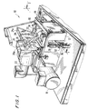
- Figs. 1 and 2 illustrate an apparatus particularly adapted for grinding points on needle stock, for example, point grinding apparatus 10. While the following description will focus on an apparatus and methods for grinding points on surgical needles, it will be appreciated by those having ordinary skill in the art that the present invention may be used to grind other objects as well. For example, the present invention may be used to grind points on many different types of elongated workpiece stock.
- Apparatus 10 generally includes frame 12; grinding wheel 14, mounted on spindle 16 and driven by drive motor 18; and transport wheel 20, driven by motor 22.
- components of apparatus 10 are generally made of aluminum or tool steel.
- Grinding wheel 14 is preferably of the electroplated type, having a core made of aluminum or other suitable material plated with an abrasive material such as Borazon.
- abrasive material such as Borazon.
- other known abrasive materials and bonding methods therefore, may also be substituted for Borazon, for example, diamond, aluminum oxide (Al2O3) or silicon carbide (SiC).
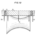
- the geometry of grinding wheel 14 is unique in that it has a generally asymmetrical concave shape, with one end thereof having a greater diameter than the other end, as illustrated in Figs. 3 (in phantom lines), 6-9 and 11.
- This asymmetrical shape is best illustrated in Fig. 11, where the surface of grinding wheel 14 is shown having unequal length radii of curvature R1 and R2 which are corresponding, in that each radius is formed at an angle T with respect to center line 13.
- the surface of grinding wheel 14 has radii of curvature on one side of center line 13 running through grinding wheel 14 which correspond to radii of curvature on the other side of center line 13 which are equally displaced therefrom.
- These corresponding radii of curvature are of unequal length.
- prior grinding wheels In prior grinding wheels, the corresponding radii of curvature are of equal length, i.e. , prior grinding wheels have symmetrical grinding surfaces.
- the benefit of the present invention's grinding wheel geometry will become apparent from the description of the operation of apparatus 10 presented further below.
- Saddle 27 is shaped to conform to the curvature of transport wheel 20 and is provided so that needle stock 25 are supported in contact with transport wheel 20 as they traverse the surface of grinding wheel 14. Frictional surfaces such as rubber layer 29 and rubber layer 31 are provided on saddle 27 and transport wheel 20, respectively, to supply traction for needle stock 25 travelling between the two surfaces.
- Workpiece storage is provided by feed hopper 24 and ground workpiece receiving is provided by off-load hopper 26.
- Hoppers 24 and 26 are provided to respectively deliver and receive workpieces, for example, needle stock 25, to feed point 33 and off-load point 35 between saddle 31 and transport wheel 20, before and after grinding takes place.
- Feed hopper 24 has inlet opening 24a for receiving workpieces 25 to be ground and outlet 24b for supplying workpieces 25 to feed point 33.
- Off-load hopper 26 has inlet portion 26b for receiving ground workpieces 25a. Also provided on off-load hopper 26 is opening 26a for removing ground workpieces 25a.
- a workpiece agitating device may be provided on apparatus 10 to introduce vibrations within feed hopper 24.
- Other devices may be utilized, for example, pneumatically, hydraulically, or electrically operated devices mounted on apparatus 10 such that workpiece stock 25 is prevented from jamming at feed point 33.
- feed hopper 24 Mounted on the side of feed hopper 24 is a sensing device such as photo sensor 23 which detects the presence of workpieces in the hopper. Banner reflective type photo sensors have been found effective, however, other suitable sensors may also be used. Sensor 23 is preferably mounted at a position near the bottom of feed hopper 24 so that when sensor 23 detects a low level of workpieces in the feed hopper, a warning signal is communicated to the operator. In a preferred embodiment, where it is intended that feed hopper 24 be attached to apparatus 10 when full and replaced with another full hopper when empty, it is preferred that sensor 23 triggers an alarm when the feed hopper is virtually empty. In this manner, another feed hopper can be attached to apparatus 10 for grinding of another batch of workpieces. In another embodiment, where the feed hopper is intended to remain fixed to apparatus 10, it is preferred that a sufficient amount of stock remain in feed hopper 24 at the time sensor 23 triggers an alarm, in order that feed hopper 24 can be refilled without unnecessary interruption of the production process.
- Grinding wheel adjusting devices for example, micrometers 28 and 30, are mounted on blocks 32 and 34 and rest on micrometer bearing posts 36 and 38, respectively, for adjusting the position of the longitudinal axis of grinding wheel 14.
- Other adjusting devices are provided for adjusting the vertical and horizontally pivotal relationship of transport wheel 20 with respect to grinding wheel 14. Together the different adjustment capabilities allow for precision grinding of the needle stock.
- Feed hopper 24 is supplied with needle stock 25 and mounted on workpiece saddle 27 by threaded screw 70 or any other suitable fastener.
- Grinding wheel 14 is rotated counter-clockwise, at a rate of approximately 1,000 to 20,000 revolutions per minute by grinding wheel drive motor 18.
- the preferred operating speed of grinding wheel 14 depends on the diameter of the wire, the diameter of the wheel 14, the type of wire and wheel materials used as well as surface finish requirements.
- Transport wheel 20 is rotated by transport wheel drive motor 22 in an orientation substantially transverse to the rotation of grinding wheel 14, in a counter-clockwise direction as indicated by arrow A.
- transport wheel 20 is rotated much slower than grinding wheel 14, at a rate of approximately 1 to 5 revolutions per minute depending on the diameter of the wire, diameter of the transport wheel 20, wire material, wheel material and surface finish requirements.
- direction of travel of the grinding wheel and the transport wheel may be reversed so that the operation would work in the reverse direction.
- Needle stock 25 are fed between transport wheel 20 and saddle 27 at feed point 33, thereby frictionally contacting rubber layer 29 and rubber layer 31 of transport wheel 20 and saddle 27, respectively.
- a contact force is applied to the needle stock from downward pressure provided thereon by transport wheel 20, which force causes the ends of needle stock 25 to contact grinding wheel 14.
- the pressure exerted by transport wheel 20 on the needle stock may be adjusted by micrometer 42 to either raise or lower transport wheel 20.
- the rotation of transport wheel 20 and frictional contact with rubber layers 29 and 31 causes the stock to rotate in the direction of arrow B so that the ends of needle stock 25 are evenly exposed to the grinding action of grinding wheel 14.
- needle stock 25a exit at point 35 and are deposited into off-load hopper 26.
- Some point configurations may require more than one pass over the grinding surface or different adjustment of the transport and/or grinding wheels' alignment depending on the type of material being ground or the point desired. In these instances, a full batch of needle stock 25 are completed one pass at a time until sufficient material has been removed from each needle stock workpiece 25.
- the length of the finished needle point may be controlled by moving platform 66 with transport wheel drive motor 22 mounted thereon toward or away from grinding wheel 14 and raising or lowering grinding wheel 14 with respect to transport wheel 20.
- micrometers 28 and 30 To raise or lower grinding wheel 14, micrometers 28 and 30 (Fig. 2) are adjusted, causing spindle blocks 46 and 48 to raise or lower spindle 16 (Fig. 1) which moves grinding wheel 14 up or down with respect to transport wheel 20.
- Figs. 6-9 illustrate other adjustments which may be used to form different needle point geometries.
- Figs. 6-8 illustrate other adjustments for grinding wheel 14.
- grinding wheel 14 may be moved horizontally or vertically with respect to the face of transport wheel 20 as shown in Figs. 6 and 7, respectively. Grinding wheel 14 may also be skewed with respect to the face of transport wheel 20 as shown in Fig. 8.
- Fig. 9 shows one possible adjustment for transport wheel 20 with respect to grinding wheel 14 wherein transport wheel 20 may be skewed along a horizontal plane formed with grinding wheel 14 as seen in the top view shown.
- FIG. 12 another embodiment of the present invention apparatus 110 is illustrated having grinding wheel 114 attached to drive motor 118 by spindle 116.
- Grinding wheel 114 has the same unique geometry as that described above for grinding wheel 14 except that grinding wheel 114 is a much smaller version with a maximum diameter on the order of one inch.
- Transport wheel 120 is provided and is driven by a drive motor (not shown). The operation of apparatus is similar to that of that described above for apparatus 10.
- Apparatus 110 is useful for grinding points on extremely small surgical needles such as those used for microsurgery, ophthalmic surgery and plastic surgery.
- only feed hopper 124 is shown. Needle stock 125 are ground and fed to ramp 121 which they roll or slide down into bin 123. It is also envisioned that apparatus 110 could be provided with an off-load hopper as described and illustrated for apparatus 10.
Landscapes
- Engineering & Computer Science (AREA)
- Mechanical Engineering (AREA)
- Grinding And Polishing Of Tertiary Curved Surfaces And Surfaces With Complex Shapes (AREA)
- Grinding Of Cylindrical And Plane Surfaces (AREA)
Applications Claiming Priority (2)
| Application Number | Priority Date | Filing Date | Title |
|---|---|---|---|
| US959054 | 1992-10-09 | ||
| US07/959,054 US5388374A (en) | 1992-10-09 | 1992-10-09 | Apparatus and method for grinding points |
Publications (1)
| Publication Number | Publication Date |
|---|---|
| EP0591998A1 true EP0591998A1 (de) | 1994-04-13 |
Family
ID=25501617
Family Applications (1)
| Application Number | Title | Priority Date | Filing Date |
|---|---|---|---|
| EP93116348A Withdrawn EP0591998A1 (de) | 1992-10-09 | 1993-10-08 | Verfahren und Vorrichtung zum Schleifen von Spitzen |
Country Status (3)
| Country | Link |
|---|---|
| US (2) | US5388374A (de) |
| EP (1) | EP0591998A1 (de) |
| CA (1) | CA2106787A1 (de) |
Cited By (1)
| Publication number | Priority date | Publication date | Assignee | Title |
|---|---|---|---|---|
| WO2005095051A1 (en) | 2004-03-31 | 2005-10-13 | Eastland Medical Systems Ltd | Jig |
Families Citing this family (6)
| Publication number | Priority date | Publication date | Assignee | Title |
|---|---|---|---|---|
| US5477604A (en) * | 1993-11-01 | 1995-12-26 | Smith; Daniel | Process for manufacturing taper point surgical needles |
| AU2003900366A0 (en) * | 2003-01-23 | 2003-02-13 | Portland Surgical Products Pty. Ltd | Hypodermic needles and other small diameter components |
| US7435159B2 (en) * | 2003-01-23 | 2008-10-14 | Eastland Medical Systems Ltd. | Rotary jig |
| EP1833626A1 (de) * | 2005-01-07 | 2007-09-19 | Eastland Medical Systems Ltd | Einspannvorrichtung |
| CN109015298B (zh) * | 2018-09-10 | 2024-06-04 | 扬州四星工业自动化设备有限公司 | 一种钢板双面除油除锈打磨机及其操作方法 |
| CN116494085A (zh) * | 2023-05-16 | 2023-07-28 | 河北圣昊光电科技有限公司 | 一种探针尖端打磨机及打磨方法 |
Citations (3)
| Publication number | Priority date | Publication date | Assignee | Title |
|---|---|---|---|---|
| US1486435A (en) * | 1920-08-17 | 1924-03-11 | Jonathan A Hunt | Rod-grinding machine |
| JPS4914613B1 (de) * | 1970-09-05 | 1974-04-09 | ||
| DE3141276A1 (de) * | 1980-11-12 | 1982-08-05 | Veb Kombinat Textima, Ddr 9010 Karl-Marx-Stadt | Verfahren und vorrichtung zum spitzenlosen schleifen rotationssymmetrischer werkstuecke |
Family Cites Families (13)
| Publication number | Priority date | Publication date | Assignee | Title |
|---|---|---|---|---|
| US1175831A (en) * | 1915-01-15 | 1916-03-14 | Almon I Spinney | Skewer-pointing machine. |
| US2109450A (en) * | 1935-02-09 | 1938-03-01 | Northam Warren Corp | Method of and mechanism for shaping manicure sticks |
| US2170672A (en) * | 1936-11-27 | 1939-08-22 | Gen Electric | Apparatus for abrading coatings from rods |
| US2475009A (en) * | 1946-06-15 | 1949-07-05 | Walter H Catucci | Machine for grinding objects |
| US2528042A (en) * | 1947-04-01 | 1950-10-31 | Putnam Needle Company | Machine for grinding down conical points of drawn steel rods |
| US3133382A (en) * | 1960-10-22 | 1964-05-19 | Messerschmidt Sebastian | Apparatus for grinding balls |
| DE2218288A1 (de) * | 1972-04-15 | 1973-10-31 | Merck Patent Gmbh | Verfahren zur reinigung von l-dopa |
| US4112625A (en) * | 1975-08-21 | 1978-09-12 | Schumag Schumacher Metallwerke Gesellschaft Mit Beschankter Haftung | Device for grinding elongated cylindrical workpieces |
| DE2537151C3 (de) * | 1975-08-21 | 1978-10-12 | Schumag Gmbh, 5100 Aachen | Verfahren und Vorrichtung zum Schleifen von langgestreckten, zylindrischen Werkstücken im Durchlauf |
| DE2949538C2 (de) * | 1979-12-10 | 1982-01-21 | Schumag Gmbh, 5100 Aachen | Vorrichtung zum spitzenlosen Schleifen von rotationssymmetrischen Oberflächen an Werkstücken |
| KR910003131B1 (ko) * | 1987-03-10 | 1991-05-20 | 미쯔비시주우고오교오 가부시기가이샤 | 전착숫돌 |
| US4977709A (en) * | 1989-05-19 | 1990-12-18 | Inovac Ab | Abrasive wheel |
| US5155943A (en) * | 1990-01-12 | 1992-10-20 | Matsutani Seisakusho Co., Ltd. | Suture needle and method of an apparatus for grinding material for suture needle |
-
1992
- 1992-10-09 US US07/959,054 patent/US5388374A/en not_active Expired - Lifetime
-
1993
- 1993-09-23 CA CA002106787A patent/CA2106787A1/en not_active Abandoned
- 1993-10-08 EP EP93116348A patent/EP0591998A1/de not_active Withdrawn
-
1994
- 1994-06-28 US US08/266,743 patent/US5501630A/en not_active Expired - Lifetime
Patent Citations (3)
| Publication number | Priority date | Publication date | Assignee | Title |
|---|---|---|---|---|
| US1486435A (en) * | 1920-08-17 | 1924-03-11 | Jonathan A Hunt | Rod-grinding machine |
| JPS4914613B1 (de) * | 1970-09-05 | 1974-04-09 | ||
| DE3141276A1 (de) * | 1980-11-12 | 1982-08-05 | Veb Kombinat Textima, Ddr 9010 Karl-Marx-Stadt | Verfahren und vorrichtung zum spitzenlosen schleifen rotationssymmetrischer werkstuecke |
Non-Patent Citations (1)
| Title |
|---|
| DATABASE WPI Week 7418, Derwent World Patents Index; AN 74-33781V, "mfr of diamond grindstones" * |
Cited By (2)
| Publication number | Priority date | Publication date | Assignee | Title |
|---|---|---|---|---|
| WO2005095051A1 (en) | 2004-03-31 | 2005-10-13 | Eastland Medical Systems Ltd | Jig |
| EP1729919A4 (de) * | 2004-03-31 | 2009-12-23 | Eastland Medical Systems Ltd | Spannvorrichtung |
Also Published As
| Publication number | Publication date |
|---|---|
| US5388374A (en) | 1995-02-14 |
| US5501630A (en) | 1996-03-26 |
| CA2106787A1 (en) | 1994-04-10 |
Similar Documents
| Publication | Publication Date | Title |
|---|---|---|
| US5447463A (en) | Apparatus for microfinishing | |
| US7367868B2 (en) | Centerless grinder | |
| EP0295586A1 (de) | Methode und Vorrichtung zur Erzeugung von Schneidkanten | |
| US6283837B1 (en) | Grinding machine | |
| KR102542334B1 (ko) | 그루브가 있는 워크피스를 연삭하기 위한 방법 및 연삭 머신 | |
| US4760668A (en) | Surface grinding machine and method | |
| JPS60255320A (ja) | ワイヤまたはストリツプ状切断電極の案内装置 | |
| US5551908A (en) | Centerless grinder and wheel truing device therefor | |
| US5501630A (en) | Method for grinding needle points on surgical grade needle blanks | |
| US6415997B1 (en) | Process and apparatus for manufacturing chopped thermoplastic fibers | |
| JPH10217095A (ja) | ワイヤーソーによるワークの切断方法およびワイヤーソー | |
| EP0656243B1 (de) | Verfahren und Vorrichtung zum Schleifen von Nadeln | |
| JPS6316955A (ja) | 薄板研摩方法 | |
| JP2000135663A (ja) | 被加工物自転型ワイヤソー及びウェハ製造方法 | |
| JPH07256541A (ja) | 断面円形工作物の研摩方法 | |
| CN1014876B (zh) | 铝合金精密细长轴的无心磨削工艺 | |
| JPH09285950A (ja) | 研磨装置及び研磨方法 | |
| JPH0890394A (ja) | 円筒ロールの研削方法および装置 | |
| JP3690397B2 (ja) | ラッピング加工装置およびラッピング加工方法 | |
| Warburton | Grinding | |
| JPS6393553A (ja) | 芯無研削装置 | |
| JPS6179567A (ja) | 砥石修正装置 | |
| JPH0436826B2 (de) | ||
| JPH09122715A (ja) | 圧延ロールの研削方法および装置 | |
| JPH0533522B2 (de) |
Legal Events
| Date | Code | Title | Description |
|---|---|---|---|
| PUAI | Public reference made under article 153(3) epc to a published international application that has entered the european phase |
Free format text: ORIGINAL CODE: 0009012 |
|
| AK | Designated contracting states |
Kind code of ref document: A1 Designated state(s): DE FR GB IT |
|
| 17P | Request for examination filed |
Effective date: 19940727 |
|
| 17Q | First examination report despatched |
Effective date: 19941103 |
|
| STAA | Information on the status of an ep patent application or granted ep patent |
Free format text: STATUS: THE APPLICATION HAS BEEN WITHDRAWN |
|
| 18W | Application withdrawn |
Withdrawal date: 19960401 |