EP0592708A1 - Procédé et appareil pour le traitement des plaques dans un courant gazeux - Google Patents
Procédé et appareil pour le traitement des plaques dans un courant gazeux Download PDFInfo
- Publication number
- EP0592708A1 EP0592708A1 EP92117516A EP92117516A EP0592708A1 EP 0592708 A1 EP0592708 A1 EP 0592708A1 EP 92117516 A EP92117516 A EP 92117516A EP 92117516 A EP92117516 A EP 92117516A EP 0592708 A1 EP0592708 A1 EP 0592708A1
- Authority
- EP
- European Patent Office
- Prior art keywords
- plates
- chamber
- column
- walls
- gaseous medium
- Prior art date
- Legal status (The legal status is an assumption and is not a legal conclusion. Google has not performed a legal analysis and makes no representation as to the accuracy of the status listed.)
- Withdrawn
Links
Images


Classifications
-
- C—CHEMISTRY; METALLURGY
- C23—COATING METALLIC MATERIAL; COATING MATERIAL WITH METALLIC MATERIAL; CHEMICAL SURFACE TREATMENT; DIFFUSION TREATMENT OF METALLIC MATERIAL; COATING BY VACUUM EVAPORATION, BY SPUTTERING, BY ION IMPLANTATION OR BY CHEMICAL VAPOUR DEPOSITION, IN GENERAL; INHIBITING CORROSION OF METALLIC MATERIAL OR INCRUSTATION IN GENERAL
- C23C—COATING METALLIC MATERIAL; COATING MATERIAL WITH METALLIC MATERIAL; SURFACE TREATMENT OF METALLIC MATERIAL BY DIFFUSION INTO THE SURFACE, BY CHEMICAL CONVERSION OR SUBSTITUTION; COATING BY VACUUM EVAPORATION, BY SPUTTERING, BY ION IMPLANTATION OR BY CHEMICAL VAPOUR DEPOSITION, IN GENERAL
- C23C8/00—Solid state diffusion of only non-metal elements into metallic material surfaces; Chemical surface treatment of metallic material by reaction of the surface with a reactive gas, leaving reaction products of surface material in the coating, e.g. conversion coatings, passivation of metals
- C23C8/06—Solid state diffusion of only non-metal elements into metallic material surfaces; Chemical surface treatment of metallic material by reaction of the surface with a reactive gas, leaving reaction products of surface material in the coating, e.g. conversion coatings, passivation of metals using gases
- C23C8/08—Solid state diffusion of only non-metal elements into metallic material surfaces; Chemical surface treatment of metallic material by reaction of the surface with a reactive gas, leaving reaction products of surface material in the coating, e.g. conversion coatings, passivation of metals using gases only one element being applied
- C23C8/24—Nitriding
Definitions
- This invention relates to the treatment of apertured plates with a gas.
- the invention has been developed for treating thin steel plates with a nitriding or nitrocarburizing gaseous medium to form an iron nitride layer on the surfaces of the plates.
- the invention provides an apparatus for such treatment, a treatment method and a fastening device on which a plurality of plates can be carried during treatment.
- the device provided for solving the first task part is characterized by opposite end walls and a chamber defined between the end walls, bottom wall, top wall and side walls, by means for circulating a gaseous medium in the chamber in a general direction from one end wall to the other end wall; Means for holding said plates in the chamber at a mutual distance in several adjacent rows which are generally parallel to said end walls so that the surfaces of the plates are parallel to the side walls and to said general direction of flow and by means of deflecting means on at least some of the Floor, ceiling or side walls to redirect the gas flowing along said walls towards and parallel to said rows so that the gas flow on the plates is substantially uniform.
- deflecting means makes it possible to accommodate a large number of plates for effective treatment in the device due to the uniformity of the gas flow on the plates.
- the deflecting means comprise a plurality of deflecting bodies which are attached to and protrude from at least some of the floor, ceiling and side walls mentioned, the projection of the deflecting bodies with which they are removed from the wall to which they are attached, project, the greater the closer the deflecting body in question is to the other end wall of the chamber.
- a device for solving the task is further provided, a chamber defined by opposite end walls and between these end walls bottom wall, ceiling wall and side walls; by means for circulating a gaseous medium in the chamber in a general direction from one end wall to the other end wall, by a fastening device for holding said plates in the chamber, which a base frame with opposite sides, a group of mounted on each of said sides vertical columns, each column of one group being aligned on one side with a column arranged on the other side so that they form a pair, a plurality of support rails, each running between a pair of columns, so that the support rails are arranged generally parallel to the end walls and each pair of columns has a plurality of support rails, each rail being designed so that it can be passed through the openings of a plurality of said plates in order to hold the latter in rows and that it has fixing agents to the pla in fixed positions at a mutual distance hold an apertured end piece at the ends of each support rail, each of these end pieces having an opening for the passage of
- One of said end walls may be in the form of a door, and said chamber may include means by which the fastener can be moved into and out of said chamber through the door.
- Said means for moving the fastening device in and out of the chamber can preferably comprise a roller conveyor which is fastened to the bottom wall of the chamber.
- the invention also provides a method of treating plates with a gaseous medium in a chamber, which is characterized in that a gaseous medium is circulated in a general direction from said one end wall to the other, the plates being solid in the chamber Positions and with a mutual distance in several neighboring, parallel are attached to the end walls of the rows so that the faces of the plates are parallel to the general direction of flow of the gaseous medium in the chamber and the gaseous medium flowing along said walls is deflected such that it is directed towards and between the rows flows and the gas flow is substantially uniform on all plates.
- the plates are preferably provided with openings and are provided in the said rows with openings aligned with one another, so that the said deflected gaseous medium also flows into the aligned openings of the rows of plates.
- the plates are kept at a distance, namely in the recesses of the mounting rails, in that the mounting rails are pushed through the aligned openings of each row of plates.
- the plates are made of steel and are heated in the chamber in an inert atmosphere, which is then suctioned off and replaced by said gaseous medium, which is a nitriding or nitrocarburizing medium, which is heated and circulated so that there is a surface layer of iron nitride on the surface mentioned plates forms.
- said gaseous medium which is a nitriding or nitrocarburizing medium
- the invention also provides a fastener for supporting a plurality of plates during treatment with a gaseous medium, characterized in that it comprises a base frame with opposite sides on each of the sides a group of vertical columns built up, each column of the one group on said one side being aligned with a column which is mounted on said other side and these form a pair, a plurality of support rails, each of which runs between said pair of columns, so that the support rails are generally parallel to one another, a number of support rails on each of these pairs of columns, each support rail being designed so that it can be passed through the openings in a number of said plates to hold the latter in rows, and over Fixing means to keep the plates lined up on them in fixed positions and at a distance from each other and has an end piece with openings at the ends of each support rail, which can be passed through the column and spacer tubes on each column between the end pieces of support rails located one above the other on the Pillar that the Tr Keep rails on the column at a vertical distance.
- the fixing means on the mounting rails are represented by depressions, which are preferably V-shaped to accommodate the edges of the openings in the plates.
- the mounting rails can be made from an upwardly open V-profile, the recesses being formed in the opposite sides of the V-shape.
- At least one connecting rod can connect the columns of each group near the top of the columns.
- it has openings to accommodate the columns. It is designed as an angle profile between the openings mentioned.
- Each of the columns mentioned can consist of several individual parts that can be plugged into one another. This allows the fastener to be set up while the panels are set up on it.
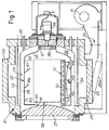
- the heating furnace comprises a central chamber 20 which is arranged within a furnace structure, generally designated 21.
- the heating furnace has an outer housing 22 made of refractory and heat-insulating material and a furnace lining 23. Between the housing 21 and the furnace lining 23 there are heating elements, two of which are shown at 24.
- a pipe 25 has a connection to the furnace lining 23 and runs through the housing 22 and allows the introduction of gaseous treatment medium into the interior of the furnace lining. There is a space between the furnace lining 23 and the outside of the chamber 20.
- the oven assembly 21 carries a door 27 which fits into the left end of the oven liner 23 to close the oven.
- the door 27 can be opened by moving it to the left in FIG. 1 and then lifting it by means not shown.
- a lower wall 28 of the furnace structure is pivotally mounted at 29 so that it can be moved to the position 28a shown in phantom, thereby creating a ventilation duct 30 is connected to the inside of the furnace lining 23.
- the ventilation duct 30 is connected to a suction fan 31, which enables gas to be extracted from the heating furnace.
- the chamber 20 is defined by floor and ceiling walls 32 and 33, side walls 34 and end walls 35 and 36.
- the end wall 35 has a central opening 37, in which a circulating fan 38 is mounted, which is arranged so that it sucks gas out of the chamber 20 and transfers it into the space 28 between the chamber 20 and the furnace lining 23.
- the circulation fan 38 is driven by an electric motor 39.
- the end wall 36 of the chamber 20 has an opening 40 which is partially closed by the door 27 and which in this way forms part of the left end wall of the chamber.
- the space 41 between the opening 40 and the door 27 communicates with the space 26 and the interior of the chamber 20.
- Each of the walls 32 to 34 is provided with three baffle plates 42-50.
- the bottom wall 32 is accordingly provided with the deflection plates 42, 43 and 44.
- the baffle plates 42-50 are inclined to the right towards the wall 36 in the drawing, and it can be seen that the baffle plates 42-50 project further from the wall 32 the closer they are to the wall 35.
- the baffle plate 44 thus projects further from the wall 32 than the baffle plate 43 and the latter further from the wall 32 than the baffle plate 42.
- the top wall 33 has three deflection plates 45, 46 and 47 and each of the side walls 34 is provided with three deflection plates 48, 49 and 50.
- all the baffle plates 42-50 are inclined to the right towards the wall 35 and they are all in the same type as described with reference to the baffle plates 42 to 44, ie the baffle plates which are closer to the wall 35 project further from the wall to which they are attached than the baffle plates which are further from the wall 35 are removed.
- the bottom wall 32 of the chamber carries a roller conveyor 51 which receives a fastening device 52, which will be described below and which are arranged on the plates for treatment in the chamber.
- the fastener can be moved into and out of the chamber 20 when the door 27 is open.
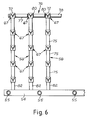
- the fastening device 52 comprises a base frame 53, the opposite sides 54 of which, as shown in FIGS. 5 and 6, are shown in the form of square tubes which are kept at a distance by six cross members 55.
- Each side 54 of the base frame carries ten vertical columns 56, each column 56 on one side 4 of the base frame 53 being aligned with a corresponding column 56 on the other side 4 of the base frame 53.
- the base of each column 56 comprises a cylindrical tube 57 which is welded into aligned openings in the upper and lower walls 58 and 59 of one side 54 to project upwardly from side 54.
- a cylindrical reinforcing bar 60 is received in the lower part of the tube, while the upper part thereof forms a sleeve 61.
- Each column 56 is constructed on a tube 57 from a number of components, such as part 62 and spacer tubes, as shown in FIGS. 8 and 9, respectively.
- Each component 62 has a cylindrical tube 63 with the same diameter as the tube 57 and a pin 64 which is dimensioned such that it fits into the sleeve 61 of the tube 57 and fits into a similar sleeve 65 in the tube 63 of another component 62.
- the tube 63 and the pin 65 are welded at 66.
- a column 56 is built on a tube 57 by inserting the pin 64 of one component 62 into the sleeve 61 and then inserting the pin 64 of another component 62 into the sleeve 65 of the component already in position on the column and so on.
- Figure 10 shows a mounting rail 67 which fits between two mutually aligned columns of the fastening device, one on each side 54 of the base frame 53.
- the mounting rail 67 has a central part 68 in a V-profile with opposite sides 69.
- a series of V-shaped depressions 70 is formed, the depressions 70 on one side 69 being arranged in alignment with those on the other side 69.
- the support rail 67 has an end piece 71, which is provided with openings and has an angular profile, the flanges of which extend vertically and horizontally.
- the vertical flanges 72 are welded to the ends of the middle parts 68 and the horizontal flanges 73 are provided with openings 74.
- the openings 74 are sized so that the tubes 57 and 63 pass through them with little play. As described further below, the openings 74 of the support rails 67 are "threaded" over the tubes 57 and 63 and vertically spaced apart from tubular spacers 75, as shown in FIG. 9, these tubular spacers being pushed over the tubes 57 and 63 .
- FIG. 11 shows a connecting rod 76 for the fastening device.
- the connecting rod is an angle profile with horizontal and vertical flanges 77 and 78.
- the flange 77 is provided with openings at 79 to receive the tubes 63 of the components 62 so that it is supported by the spacers 75.
- the openings 79 are spaced apart to receive the upper ends of the pillars 56.
- the vertical flange 76 is cut out at 80 to create a recess for the vertical flanges 72 of the mounting rails 67, as shown in FIG. 6.
- Figure 4 is a section through the entire assembled fastener carrying a plurality of apertured plates 81, the edges of which apertures are received in the recesses 70 of the support rails 67. Each plate is received in an aligned pair of recesses in a mounting rail and this holds the plates in fixed, mutually spaced positions.
- the fastening device 52 is constructed as follows and filled with plates. It starts with the base frame 53 with the tubes 57 attached to it, then an aligned pair of columns 56 is built up. The pins 64 of the components 62 are inserted into the sleeves 61 of the tubes 57 and short spacer tubes 82, similar to the spacer tubes 75, but shorter, are placed on the tubes 57. A support rail 67 is then hung with plates 81 and the openings 74 are "threaded" at their ends via the tubes 63 in order to rest on the upper ends of the spacer tubes 82. Then spacer tubes 75 are placed over the tubes 63 of the lowermost component 62.
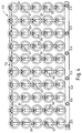
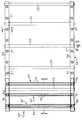
- the fastening device 52 is then placed with the plates 84 it supports in the chamber 20 of the furnace, so that the support rails 67 run parallel to the end walls 35 and 36 of the chamber, as shown schematically in FIG. 2, so that the surfaces of the plates 81 are aligned parallel to the side walls 34 of the chamber 20 and, as described later, parallel to the general direction of gas flow through the chamber 20.
- the plates 81 are preferably made of non-alloy steel or of fine-grained structural steel containing niobium and vanadium or titanium and have a thickness between 0.4 and approximately 5 mm.
- the door 27 When the fastening device 52 is inserted with its plates into the chamber 20, the door 27 is closed.
- the lower wall 28 of the furnace is pivoted downwards and the air is sucked out of the interior of the furnace by the pump 31.
- An inert atmosphere, e.g. B. nitrogen is blown into the furnace through the pipe 25 and the lower wall 28 is closed.
- the oven is then heated to a temperature between 600 and 700 degrees C by the heating elements 24.
- the inert gas is then drawn off by the pump 30 and a gaseous medium capable of covering the surfaces coating the plate 81 with a nitride layer is introduced as described in the aforementioned U.S. Patent 4,793,871.
- the inert atmosphere is circulated by a fan 38.
- the inert gas is drawn by the blower 38 from the interior of the chamber 20 and released into the space 26, from which it re-enters the left end of the chamber 20.
- the baffle plates 42 to 50 direct the flowing gas inwards towards the center of the chamber and, in this way, into the spaces between the rows of plates 81 on the support rails 67. This results in a substantially uniform gas flow over all plates 81 and so also a uniform heating of the plates 81.
- the gas flow is represented by arrows in FIGS. 2 and 3.
- the nitrogenous gas When the nitrogenous gas is introduced into the chamber 20 for treating the plates 81, it is also circulated by the blower 38 and redirected by the baffle plates 42 to 50 so that a substantially uniform flow of reactive gas is achieved across the surfaces of the plates 81 and thus ensuring a uniform coating of nitride on the plates 81.
- the baffles in the oven 42 to 50 ensure a uniform gas flow over the plate surfaces, both when heated and when they are treated, and the holding of the plates 81 in the fastening device 52, as described above, enables a large number of plates 81 to be used simultaneously to treat and, due to the baffle plates 42 to 50, exposed to a uniform gas flow.
Landscapes
- Chemical & Material Sciences (AREA)
- Chemical Kinetics & Catalysis (AREA)
- Engineering & Computer Science (AREA)
- Materials Engineering (AREA)
- Mechanical Engineering (AREA)
- Metallurgy (AREA)
- Organic Chemistry (AREA)
- Tunnel Furnaces (AREA)
- Solid-Phase Diffusion Into Metallic Material Surfaces (AREA)
Priority Applications (3)
| Application Number | Priority Date | Filing Date | Title |
|---|---|---|---|
| US07/746,793 US5186764A (en) | 1990-02-13 | 1991-08-12 | Method and apparatus for treating plates with gas |
| EP92117516A EP0592708A1 (fr) | 1991-08-12 | 1992-10-14 | Procédé et appareil pour le traitement des plaques dans un courant gazeux |
| JP4301569A JP2700745B2 (ja) | 1991-08-12 | 1992-10-15 | 鋼板処理装置およびその取付具 |
Applications Claiming Priority (3)
| Application Number | Priority Date | Filing Date | Title |
|---|---|---|---|
| US07/746,793 US5186764A (en) | 1990-02-13 | 1991-08-12 | Method and apparatus for treating plates with gas |
| EP92117516A EP0592708A1 (fr) | 1991-08-12 | 1992-10-14 | Procédé et appareil pour le traitement des plaques dans un courant gazeux |
| JP4301569A JP2700745B2 (ja) | 1991-08-12 | 1992-10-15 | 鋼板処理装置およびその取付具 |
Publications (1)
| Publication Number | Publication Date |
|---|---|
| EP0592708A1 true EP0592708A1 (fr) | 1994-04-20 |
Family
ID=27234541
Family Applications (1)
| Application Number | Title | Priority Date | Filing Date |
|---|---|---|---|
| EP92117516A Withdrawn EP0592708A1 (fr) | 1990-02-13 | 1992-10-14 | Procédé et appareil pour le traitement des plaques dans un courant gazeux |
Country Status (3)
| Country | Link |
|---|---|
| US (1) | US5186764A (fr) |
| EP (1) | EP0592708A1 (fr) |
| JP (1) | JP2700745B2 (fr) |
Families Citing this family (9)
| Publication number | Priority date | Publication date | Assignee | Title |
|---|---|---|---|---|
| US5225155A (en) * | 1991-07-22 | 1993-07-06 | Corning Incorporated | Methods and apparatus for firing extruded metals |
| US5764646A (en) * | 1996-04-02 | 1998-06-09 | Ericsson Inc. | Packet data transmission with clash subtraction |
| FR2793311B1 (fr) * | 1999-05-05 | 2001-07-27 | Snecma | Dispositif de chargement de pieces a traiter thermiquement |
| JP4131965B2 (ja) * | 2004-12-28 | 2008-08-13 | 昭和シェル石油株式会社 | Cis系薄膜太陽電池の光吸収層の作製方法 |
| US8088328B2 (en) * | 2008-06-13 | 2012-01-03 | Jones William R | Vacuum nitriding furnace |
| KR20120097792A (ko) * | 2011-02-25 | 2012-09-05 | 삼성전자주식회사 | 퍼니스와 이를 이용한 박막 형성 방법 |
| KR101414257B1 (ko) * | 2012-07-04 | 2014-08-06 | 주식회사 하이박 | 진공 질화 열처리로 |
| KR101399331B1 (ko) * | 2013-12-09 | 2014-05-28 | (주)이진히팅시스템 | 진공퍼지식 가압질화로 |
| CA2998891C (fr) | 2015-09-23 | 2020-07-07 | Consolidated Engineering Company, Inc. | Systeme pour le support de pieces coulees pendant le traitement thermique |
Citations (5)
| Publication number | Priority date | Publication date | Assignee | Title |
|---|---|---|---|---|
| US3201290A (en) * | 1960-06-17 | 1965-08-17 | Maag Zahnraeder & Maschinen Ag | Process for automatically controlled carburizing of the surface layer of steel articles |
| US3698698A (en) * | 1971-02-16 | 1972-10-17 | Abar Corp | Fixture for heat treating furnaces |
| GB1461295A (en) * | 1973-05-17 | 1977-01-13 | Aichelin Fa J | Process for the production of epsilon-carconitride layers on ferrous metal parts |
| GB2155046A (en) * | 1981-12-16 | 1985-09-18 | Ae Plc | Surface treatment of metal rings |
| DE3612375A1 (de) * | 1986-04-12 | 1987-10-15 | Heraeus Schott Quarzschmelze | Beladevorrichtung zur aufnahme von in einem ofen zu behandelnde substratscheiben |
Family Cites Families (6)
| Publication number | Priority date | Publication date | Assignee | Title |
|---|---|---|---|---|
| US2067896A (en) * | 1931-07-14 | 1937-01-19 | Nitricastiron Corp | Surface hardened cast iron articles of manufacture |
| JPS5125533U (fr) * | 1974-08-15 | 1976-02-25 | ||
| JPS5211176A (en) * | 1975-07-18 | 1977-01-27 | Toshiba Corp | Activation gas reaction apparatus |
| JPS5319111A (en) * | 1976-08-06 | 1978-02-22 | Fuaanesu Jiyuukou Kk | Continuous furnace |
| US4593644A (en) * | 1983-10-26 | 1986-06-10 | Rca Corporation | Continuous in-line deposition system |
| JPS60165370A (ja) * | 1984-02-07 | 1985-08-28 | Ishikawajima Harima Heavy Ind Co Ltd | ステンレス鋼の窒化処理方法 |
-
1991
- 1991-08-12 US US07/746,793 patent/US5186764A/en not_active Expired - Fee Related
-
1992
- 1992-10-14 EP EP92117516A patent/EP0592708A1/fr not_active Withdrawn
- 1992-10-15 JP JP4301569A patent/JP2700745B2/ja not_active Expired - Lifetime
Patent Citations (5)
| Publication number | Priority date | Publication date | Assignee | Title |
|---|---|---|---|---|
| US3201290A (en) * | 1960-06-17 | 1965-08-17 | Maag Zahnraeder & Maschinen Ag | Process for automatically controlled carburizing of the surface layer of steel articles |
| US3698698A (en) * | 1971-02-16 | 1972-10-17 | Abar Corp | Fixture for heat treating furnaces |
| GB1461295A (en) * | 1973-05-17 | 1977-01-13 | Aichelin Fa J | Process for the production of epsilon-carconitride layers on ferrous metal parts |
| GB2155046A (en) * | 1981-12-16 | 1985-09-18 | Ae Plc | Surface treatment of metal rings |
| DE3612375A1 (de) * | 1986-04-12 | 1987-10-15 | Heraeus Schott Quarzschmelze | Beladevorrichtung zur aufnahme von in einem ofen zu behandelnde substratscheiben |
Also Published As
| Publication number | Publication date |
|---|---|
| JPH06128718A (ja) | 1994-05-10 |
| US5186764A (en) | 1993-02-16 |
| JP2700745B2 (ja) | 1998-01-21 |
Similar Documents
| Publication | Publication Date | Title |
|---|---|---|
| EP0712481A1 (fr) | Procede et dispositif de sechage de panneaux | |
| DE1433509A1 (de) | Herdraumwaende,insbesondere Rueckwaende von Industrieoefen,z.B. Siemens-Martin-OEfen | |
| EP0592708A1 (fr) | Procédé et appareil pour le traitement des plaques dans un courant gazeux | |
| EP0089408B1 (fr) | Procédé et dispositif pour la ventilation de la matière à sécher dans un tunnel de séchage | |
| DE2051743A1 (de) | Einsatzhartungsanlage | |
| DE3049162A1 (de) | Trocknungsvorrichtung fuer keramikwaren | |
| DE2904243A1 (de) | Verfahren und vorrichtung zum trocknen von bauholz | |
| DE3832734C1 (fr) | ||
| DE19747018A1 (de) | Vorrichtung zur Wärmebehandlung von Werkstücken | |
| DE2009416A1 (de) | Verfahren und Vorrichtung zur Behandlung von Glasscheiben | |
| EP3048404B1 (fr) | Dispositif de changement de rouleau porteur et procédé de changement de rouleau porteur | |
| DE2501360B2 (de) | Vakuum-Atmosphärenofen zur Wärmebehandlung von Werkstücken | |
| DE3128655C2 (de) | Ofen für die Wärmebehandlung von Glasscheiben | |
| WO2025036528A1 (fr) | Système de régulation de température permettant de réguler la température de pièces, et procédé de régulation de la température de pièces | |
| DE19858305C1 (de) | Heißlufttrockner für eine Beschichtungsanlage | |
| DE3434906C2 (de) | Vorrichtung zum Vorwärmen von metallischem Gut | |
| DE69901466T2 (de) | Brennofen insbesondere für keramische Erzeugnisse | |
| DE2115640C3 (de) | Trocknungsanlage zum trocknen von einseitig offenen behaeltern, z.b. dosen | |
| DE10028895A1 (de) | Vakuum-Trockenschrank und Verfahren zum Trocknen und zur Reinigung des Vakuum-Trockenschrankes | |
| DE3246196C2 (de) | Ofen zum Glühen zylindrischer metallischer Körper | |
| DE2259410C2 (de) | Anlage zur Herstellung einbaufertiger Betonteile | |
| DE1236900B (de) | Vorrichtung zum Herstellen von metallischen UEberzuegen auf plattenfoermigen Koerpern oder Werkstuecktraegern durch Vakuum-Aufdampfen | |
| AT408177B (de) | Wärmeisolierendes wandelement für backöfen, waffelbacköfen, waffelbackmaschinen oder dergleichen | |
| EP0120378A2 (fr) | Procédé et four-tunnel pour le frittage de pastilles vertes | |
| DE2556721A1 (de) | Hubbalkenofen |
Legal Events
| Date | Code | Title | Description |
|---|---|---|---|
| PUAI | Public reference made under article 153(3) epc to a published international application that has entered the european phase |
Free format text: ORIGINAL CODE: 0009012 |
|
| 17P | Request for examination filed |
Effective date: 19930806 |
|
| AK | Designated contracting states |
Kind code of ref document: A1 Designated state(s): AT DE FR GB IT |
|
| RAP1 | Party data changed (applicant data changed or rights of an application transferred) |
Owner name: GKN VISCODRIVE GMBH |
|
| 17Q | First examination report despatched |
Effective date: 19940816 |
|
| STAA | Information on the status of an ep patent application or granted ep patent |
Free format text: STATUS: THE APPLICATION HAS BEEN WITHDRAWN |
|
| 18W | Application withdrawn |
Withdrawal date: 19950401 |