EP0592765A2 - Verfahren zur Herstellung von bipolaren Transistoren mit Heteroübergang - Google Patents
Verfahren zur Herstellung von bipolaren Transistoren mit Heteroübergang Download PDFInfo
- Publication number
- EP0592765A2 EP0592765A2 EP93107468A EP93107468A EP0592765A2 EP 0592765 A2 EP0592765 A2 EP 0592765A2 EP 93107468 A EP93107468 A EP 93107468A EP 93107468 A EP93107468 A EP 93107468A EP 0592765 A2 EP0592765 A2 EP 0592765A2
- Authority
- EP
- European Patent Office
- Prior art keywords
- layer
- film
- emitter
- base
- forming
- Prior art date
- Legal status (The legal status is an assumption and is not a legal conclusion. Google has not performed a legal analysis and makes no representation as to the accuracy of the status listed.)
- Withdrawn
Links
Images


Classifications
-
- H—ELECTRICITY
- H10—SEMICONDUCTOR DEVICES; ELECTRIC SOLID-STATE DEVICES NOT OTHERWISE PROVIDED FOR
- H10D—INORGANIC ELECTRIC SEMICONDUCTOR DEVICES
- H10D10/00—Bipolar junction transistors [BJT]
- H10D10/01—Manufacture or treatment
- H10D10/021—Manufacture or treatment of heterojunction BJTs [HBT]
-
- H—ELECTRICITY
- H10—SEMICONDUCTOR DEVICES; ELECTRIC SOLID-STATE DEVICES NOT OTHERWISE PROVIDED FOR
- H10D—INORGANIC ELECTRIC SEMICONDUCTOR DEVICES
- H10D10/00—Bipolar junction transistors [BJT]
- H10D10/80—Heterojunction BJTs
- H10D10/821—Vertical heterojunction BJTs
-
- H—ELECTRICITY
- H10—SEMICONDUCTOR DEVICES; ELECTRIC SOLID-STATE DEVICES NOT OTHERWISE PROVIDED FOR
- H10D—INORGANIC ELECTRIC SEMICONDUCTOR DEVICES
- H10D62/00—Semiconductor bodies, or regions thereof, of devices having potential barriers
- H10D62/80—Semiconductor bodies, or regions thereof, of devices having potential barriers characterised by the materials
- H10D62/85—Semiconductor bodies, or regions thereof, of devices having potential barriers characterised by the materials being Group III-V materials, e.g. GaAs
-
- Y—GENERAL TAGGING OF NEW TECHNOLOGICAL DEVELOPMENTS; GENERAL TAGGING OF CROSS-SECTIONAL TECHNOLOGIES SPANNING OVER SEVERAL SECTIONS OF THE IPC; TECHNICAL SUBJECTS COVERED BY FORMER USPC CROSS-REFERENCE ART COLLECTIONS [XRACs] AND DIGESTS
- Y10—TECHNICAL SUBJECTS COVERED BY FORMER USPC
- Y10S—TECHNICAL SUBJECTS COVERED BY FORMER USPC CROSS-REFERENCE ART COLLECTIONS [XRACs] AND DIGESTS
- Y10S148/00—Metal treatment
- Y10S148/011—Bipolar transistors
Definitions
- the present invention relates to methods for producing semiconductor devices and, more particularly to methods for producing heterojunction bipolar transistors.
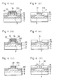
- FIGS 5(a) to 5(e) are sectional views illustrating process steps in a conventional method for producing a heterojunction bipolar transistor (hereinafter referred to as HBT).
- HBT heterojunction bipolar transistor
- an n type GaAs collector layer 2 about 1 micron thick, a p type GaAs base layer 3 about 1000 angstroms thick, and an n type AIGaAs emitter layer 4 about 3000 angstroms thick are successively grown on a semi-insulating GaAs substrate 1 by epitaxial growth.
- a tungsten silicide (WSi) film 5 4000 - 5000 angstroms thick is grown on the emitter layer 4 by sputtering, and an SiO film 6 1000 - 2000 angstroms thick is deposited on the WSi film 5 by chemical vapor deposition (CVD).
- CVD chemical vapor deposition
- the WSi film 5 and the SiO film 6 are patterned in a desired shape by conventional photolithography and reactive ion etching (RIE) using fluoric gas (figure 5(a)).
- the emitter layer 4 is etched by RIE using CI 2 gas or wet etching using, as an etchant, a mixture of tartaric acid and hydrogen peroxide water, leaving portions 41 on the base layer 3 (figure 5(b)).
- the remaining emitter layer 41 has to be as thin as 500 angstroms so that it is sufficiently depleted when the device operates.
- the etching process of figure 5(b) is referred to as a first base etching, hereinafter.
- an insulating film such as SiN
- an insulating film such as SiN
- the emitter layer is etched to expose the surface of the base layer 3. This etching process is referred to as a second base etching, hereinafter.
- a base metal 11 such as Ti/Mo/Au, is deposited on the entire surface to a thickness of about 1500 angstroms (figure 5(c)).
- a photoresist is deposited on the substrate, patterned, and annealed to form a photoresist pattern 12 that covers the surface of the base metal layer 11 except for the emitter region (figure 5(d)).
- a portion of the base metal layer 11 is removed by sputtering using Ar ions (hereinafter referred to as ion milling), forming base electrodes 111.
- ion milling Ar ions
- the SiO film 6 prevents the WSi film 5 as an emitter electrode from being etched.
- unnecessary portions of the SiO film 6 and the side walls 7 are removed to complete the structure of figure 5(e).
- the thin portions of the emitter layer 4 remaining under the side walls 7 are depleted when the device operates and prevent a generation of recombination current in that region.
- a high-speed bipolar transistor is achieved by reducing the base width, but the reduced base width causes an increase in the base resistance.
- the increase in the impurity concentration of the base layer decreases the resistance of the whole base layer, so that holes injected from the base to the emitter increase and the current gain decreases.
- the injection of holes from the base to the emitter is suppressed by a difference in energy band gaps between the base and the emitter.
- Figure 6 is an energy band diagram for explaining the above-described operation of the HBT.
- an n type AIGaAs emitter layer (E) is formed on a p type GaAs base layer (B), and the energy band gap of the emitter (E) is wider than the energy band gap of the base (B) and the collector (C).
- a forward bias is applied between the base (B) and the emitter (E)
- electrons in the AIGaAs emitter (E) region are easily injected into the GaAs base (B) region because the potential barrier ilE1 is small, but holes in the GaAs base (B) region are hardly injected into the AIGaAs emitter (E) region because of the presence of the large potential barrier AE 2 .
- the emitter current is an electron injecting current, a high emitter-to-ground current gain is achieved.
- the base resistance is reudced while keeping the heterojunction structure.
- the maximum impurity concentration achieved by the ion implantation is only 4 x 10 17 cm- 3 , the base resistance is not sufficiently reduced.
- the ion implantation adversely affects the base layer.
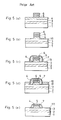
- FIG. 7(a) to 7(h) illustrates a method for producing an HBT using the solid phase diffusion method.
- an insulating film such as SiN, is deposited over the substrate and etched to form first side walls 7.
- a zinc oxide (ZnO) film 8 is deposited to a thickness of about 1000 angstroms by sputtering and annealed. During the annealing, Zn atoms diffuse into the underlying base layer 3, forming Zn diffused regions 9 having a high impurity concentration of 4 X 10 19 - 4 x 10 20 cm- 3 . Since the Zn atoms also diffuse into the thin portions 41 of the n type emitter layer 4, these portions are turned into p type. An SiO film about 1000 angstroms thick is sometimes formed on the ZnO film 8 to prevent Zn atoms from diffusing into the atmosphere.
- the ZnO film 8 is removed by hydrofluoric acid.
- the SiO film 6 and the first side walls 7 are unfavorably removed with the ZnO film 8 as shown in figure 7(e). Therefore, second side walls 10 comprising SiN or the like are formed on opposite sides of the emitter layer 4 and the WSi layer 5 (figure 7(f)).
- the emitter layer 41 is etched to expose the base layer 3 (second base etching). Thereafter, a base metal 11 is deposited on the whole surface of the substrate, and a photoresist is deposited thereon, patterned, and annealed to form a photoresist pattern 12 as shown in figure 7(g).
- the base metal 11 is selectively removed by ion milling using the photoresist pattern 12 as a mask, forming base electrodes 111. Since the SiO film 6 on the WSi film 5 has been removed in the step of figure 7(e), the WSi film 5 is subjected to the ion milling and unfavorably etched as shown in figure 7(h).
- an Si film is employed as an etching stopper layer for protecting underlying emitter electrode when a base metal is removed by ion milling.
- an SiO film covered with Si side walls and a tungsten film is employed as the etching stopper layer.
- the Si film or the SiO film covered with Si and tungsten is not etched by hydrofluoric acid when a solid phase diffusion source, i.e., zinc oxide, is removed. Therefore, the emitter electrode is not adversely affected by the ion milling for removing the base metal, providing an HBT with a reliable emitter electrode.
- the emitter electrode comprises a metal layer, and opposite side surfaces of the metal layer are oxidized. Therefore, the metal layer is not etched when the emitter layer is etched by chlorine gas. Since the emitter electrode comprises the metal layer, the resistance thereof is reduced.
- a first emitter electrode comprising a metal is removed and then a second emitter electrode comprising another metal is formed. Therefore, the degree of freedom in selecting the material of the emitter electrode increases, resulting in an HBT having an emitter electrode with desired characteristics.
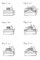
- Figures 1 (a) to 1 (I) are sectional views illustrating process steps in a method for producing an HBT in accordance with a first embodiment of the present invention.
- a semi-insulating GaAs substrate 1 600 microns thick an n type GaAs collector layer 2 about 1 micron thick, a p type GaAs base layer 3 about 1000 angstroms thick, and an n type AIGaAs emitter layer 4 about 3000 angstroms thick.
- a WSi film 5 4000 - 5000 angstroms thick is grown on the emitter layer 4 by sputtering, and a tungsten (W) film 13 about 300 angstroms thick and an Si film 14 about 1000 angstroms thick are successively grown on the WSi film 5 by CVD.
- the WSi film 5, the W film 13, and the Si film 14 are patterned in a desired shape by conventional photolithography and RIE using fluorine gas (figure 1-(a)).
- the emitter layer 4 is etched by RIE using CI 2 gas or wet etching using, as an etchant, a mixture of tartaric acid and hydrogen peroxide water, leaving portions 41 on the base layer as shown in figure 1-(b) (first base etching).
- the remaining emitter layer 41 has to be as thin as 500 angstroms so that it is sufficiently depleted when the device operates.
- a ZnO film 8 is deposited on the whole surface of the substrate and annealed to diffuse Zn atoms into the underlying base layer 3, producing Zn diffused regions 9 in the base layer 3 (figure 1-(d)). Since the Zn atoms also diffuse into the thin portions 41 of the n type emitter layer 4, these portions are turned into p type. In this way, the Zn diffused regions 9 having a high impurity con- cen t ra ti on of 4 x 10 ' 9 - 4 x 10 20 cm- 3 are formed in regions of the base layer 3 whereon base electrodes are to be produced.
- the ZnO film 8 is removed by wet etching using hydrofluoric acid.
- the first side walls comprising SiN are also etched away, but the Si film 14 is not etched because it has a resistance to hydrofluoric acid (figure 1 (e)).
- the thin portions 41 of the emitter layer 4 are etched to expose the underlying Zn diffused regions 9 as shown in figure 1 (g) (second base etching).
- a photoresist is deposited thereon, followed by patterning and annealing, forming a photoresist pattern 12 (figure 1 (h)).
- an unnecessary portion of the base metal film 11 is removed by ion milling using Ar ions (figure 1 (i)).
- the WSi film 5 as an emitter electrode is not etched because the Si film 14 serves as an etching stopper.
- the Si film 14 is removed by RIE using chlorine gas (figure 1(j)). Since the W film 13 serves as an etching stopper, the WSi film 5 is not etched.
- a contact hole is formed on the W film 13 by conventional photolithography and RIE, followed by deposition of Au or the like and lift-off, forming a leading electrode 16 (figure 1 (I)).
- the Si film 14 is formed on the WSi emitter electrode 5 in place of the SiO film 6 employed in the conventional method. Since the Si film 14 is not etched when removing the ZnO film 8 by hydrofluoric acid, it can serve as an etching stopper layer when etching the base metal 11 by ion milling. Therefore, the WSi emitter electrode 5 underlying the Si film 14 is not adversely affected by the ion milling, resulting in a reliable emitter electrode that makes a reliable contact with the leading electrode 16. As a result, an HBT with low base resistance and stable characteristics is achieved.
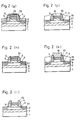
- FIGS 2(a) to 2(k) are sectional views illustrating process steps in a method for producing an HBT in accordance with a second embodiment of the present invention.
- an SiO film is formed on the WSi film, which SiO film serves as an etching stopper when base electrodes are formed by ion milling, and the top surface and side surfaces of the SiO film are covered with a W film and Si side walls, respectively.
- a collector layer 2, a base layer 3, and an emitter layer 4 are successively grown on a semi-insulating GaAs substrate 1 by epitaxial growth. Then, a WSi film 5 as an emitter electrode, an SiO film 6 as an etching stopper, and a W film 13 about 300 angstroms thick are formed on the emitter layer 4 and patterned by conventional photolithography and RIE using fluorine gas (figure 2-(a)).
- the emitter layer 4 is etched as shown in figure 2(b) (first base etching).
- an Si film is deposited on the whole surface of the substrate by sputtering or CVD and etched by RIE to form side walls 70.
- the substrate is exposed to hydrogen plasma to terminate dangling bond, improving the insulating property of the side walls 70.
- a ZnO film 8 as an impurity diffusion source is formed on the whole surface of the substrate by sputtering or the like and annealed to diffuse Zn atoms into the underlying base layer 3, forming Zn diffused regions 9 in the base layer 3.
- the ZnO film 8 is etched away by hydrofluoric acid. During the etching, the SiO film 6 is not etched because it is covered with the Si side walls 70 and the W film 13.
- a base metal 11 such as Ti/Mo/Au, is deposited on the whole surface of the substrate and selectively masked with a photoresist pattern 12 (figure 2(g)).
- unmasked portion of the base metal 11 is removed by ion milling. During the ion milling, the W film 13 about 300 angstroms thick is also removed.
- an insulating film 15 for flattening is deposited on the substrate by ECR-CVD (figure 1-(j)). Then, a contact hole is formed on the WSi film 5 by conventional photolithography and RIE, followed by deposition of Au or the like and lift-off, forming a leading electrode 16 (figure 1 (k)).
- FIGS 3(a) to 3(1) are sectional views illustrating process steps in a method for producing an HBT in accordance with a third embodiment of the present invention.
- an emitter electrode comprising a metal is formed on the emitter layer, the top surface of the emitter electrode is covered with an Si film, and side surfaces of the emitter electrode are oxidized.
- an AI film 17 3000 - 4000 angstroms thick is deposited on the emitter layer 4 by vapor deposition or sputtering, and a tungsten film 13 about 300 angstroms thick and an Si film 14 about 1000 angstroms thick are successively deposited thereon.
- These films 17, 13, and 14 are patterned as shown in figure 3(a) by conventional photolithography and RIE using fluorine gas or chlorine gas.
- the substrate is subjected to 0 2 plasma or anodic oxidation to oxidize the side surfaces of the AI film 17, forming oxide films (alumina: A1 2 0 3 ) 171 (figure 3(b)).
- the emitter layer 4 is etched as shown in figure 3(c) (first base etching). Since the oxide films 171 are present on opposite sides of the AI film 17, RIE with chlorine gas is usable for the first base etching.
- first side walls 70 comprising Si are formed as shown in figure 3(d).
- a ZnO film 8 is deposited on the whole surface of the substrate by sputtering or the like and annealed to diffuse Zn atoms into the underlying base layer 3, forming Zn diffused regions 9 in the base layer 3 whereon base electrodes are to be formed.
- the thin portions 41 of the emitter layer remaining on the base layer 3 are turned into p type.
- the ZnO film 8 is removed by wet etching using hydrofluoric acid (figure 3(f)). During the etching, the Si side walls 70 and the Si film 14 are not etched.
- the thin portions 41 of the emitter layer are removed as shown in figure 3(g) (second base etching).
- a photoresist 18 is deposited on opposite sides of the side walls 70, and the Si film 14 is removed by RIE using chlorine gas (figure 3(j)). During the RIE, since the tungsten film 13 serves as an etching stopper, the AI film 17 is not etched.
- an insulating film 15 for flattening is deposited by ECR-CVD as shown in figure 3(k). Then, a contact hole is formed on the AI film 17 as an emitter electrode by conventional photolithography and RIE, followed by a deposition of Au or the like and lift-off, forming a leading electrode 16 (figure 1 (I)).
- the AI film 17 is used as the emitter electrode, and the oxide films 171 are formed at opposite sides of the AI film 17 so that the AI film 17 is not etched during the first base etching. Since the AI film is used as the emitter electrode, the electrode resistance of the HBT is reduced as compared with the conventional HBT using the silicide film as the emitter electrode.
- Figures 4(a) to 4(f) are sectional views illustrating process steps in a method for producing an HBT according to a fourth embodiment of the present invention.
- the side walls 70, Si film 12, tungsten film 13, and AI film 17 are removed, and an emitter electrode comprising a metal other than AI is formed.
- figure 4(a) is attained according to the process steps described with respect to figures 3(a) to 3(h). That is, after depositing a base metal 11 comprising, for example, Ti/Mo/Au, a photoresist is deposited thereon, patterned, and annealed, forming a photoresist pattern 12.
- a base metal 11 comprising, for example, Ti/Mo/Au
- a photoresist is deposited thereon, patterned, and annealed, forming a photoresist pattern 12.
- An insulating film 15 for flattening is deposited by ECR-CVD (figure 4(d)), and the AI film 17 is removed by etching using hydrochloric acid (figure 4(c)).
- an emitter electrode 16 comprising Ti is formed on the emitter layer 4 by conventional deposition and lift-off.
- the degree of freedom in selecting the material of the emitter electrode increases. Since it is possible to increase the thickness of the emitter electrode 16, the electrode resistance is reduced. Since the emitter electrode 16 is directly in contact with the emitter layer 4, the surface of the device is flattened.
- the thin portions 41 of the emitter layer 4 remaining on the base electrode production regions are removed by the second base etching after the Zn diffusion, the thin portions 41 may be left because these portions are turned into p type by the Zn diffusion. In this case, the second base etching can be dispensed with.
- the emitter layer 4 may be etched until the surface of the base layer 3 is exposed in the first base etching if the etching precision can be ignored. In this case, the second base etching can be dispensed with.
Landscapes
- Bipolar Transistors (AREA)
- Weting (AREA)
Applications Claiming Priority (2)
| Application Number | Priority Date | Filing Date | Title |
|---|---|---|---|
| JP303088/92 | 1992-10-14 | ||
| JP4303088A JPH06132298A (ja) | 1992-10-14 | 1992-10-14 | 半導体装置の製造方法 |
Publications (2)
| Publication Number | Publication Date |
|---|---|
| EP0592765A2 true EP0592765A2 (de) | 1994-04-20 |
| EP0592765A3 EP0592765A3 (de) | 1998-01-14 |
Family
ID=17916750
Family Applications (1)
| Application Number | Title | Priority Date | Filing Date |
|---|---|---|---|
| EP93107468A Withdrawn EP0592765A3 (de) | 1992-10-14 | 1993-05-07 | Verfahren zur Herstellung von bipolaren Transistoren mit Heteroübergang |
Country Status (3)
| Country | Link |
|---|---|
| US (1) | US5362658A (de) |
| EP (1) | EP0592765A3 (de) |
| JP (1) | JPH06132298A (de) |
Cited By (4)
| Publication number | Priority date | Publication date | Assignee | Title |
|---|---|---|---|---|
| EP0810646A3 (de) * | 1996-05-13 | 1998-01-14 | Trw Inc. | Verfahren zur Herstellung eines Heterobipolartransistors mit sehr hohem Verstärkungsfaktor |
| DE19718624A1 (de) * | 1997-05-02 | 1998-11-05 | Daimler Benz Ag | Heterobipolartransistor mit Mehrschicht-Emitterstruktur |
| DE19834491A1 (de) * | 1998-07-31 | 2000-02-03 | Daimler Chrysler Ag | Anordnung und Verfahren zur Herstellung eines Heterobipolartransistors |
| DE10104776A1 (de) * | 2001-02-02 | 2002-08-22 | Infineon Technologies Ag | Bipolartransistor und Verfahren zu dessen Herstellung |
Families Citing this family (5)
| Publication number | Priority date | Publication date | Assignee | Title |
|---|---|---|---|---|
| DE19845790B4 (de) * | 1998-09-21 | 2008-12-04 | IHP GmbH - Innovations for High Performance Microelectronics/Institut für innovative Mikroelektronik | Verfahren zur naßchemischen Abdünnung von Si-Schichten im aktiven Emittergebiet eines Bipolartransistors |
| US7033950B2 (en) * | 2001-12-19 | 2006-04-25 | Auburn University | Graded junction termination extensions for electronic devices |
| KR101294844B1 (ko) * | 2005-12-29 | 2013-08-08 | 엘지디스플레이 주식회사 | 유기 전계 발광 표시소자의 제조방법 및 이를 이용한 유기전계 발광 표시소자 |
| US7910447B1 (en) * | 2007-05-15 | 2011-03-22 | National Semiconductor Corporation | System and method for providing a self aligned bipolar transistor using a simplified sacrificial nitride emitter |
| DE102008020576B4 (de) * | 2008-04-24 | 2018-06-28 | Bodycote Wärmebehandlung GmbH | Verfahren zum Diffusionsverzinken |
Family Cites Families (11)
| Publication number | Priority date | Publication date | Assignee | Title |
|---|---|---|---|---|
| EP0240307B1 (de) * | 1986-04-01 | 1993-12-22 | Matsushita Electric Industrial Co., Ltd. | Bipolarer Transistor und sein Herstellungsverfahren |
| DE3767431D1 (de) * | 1986-04-23 | 1991-02-21 | American Telephone & Telegraph | Verfahren zur herstellung von halbleiterbauelementen. |
| US4738624A (en) * | 1987-04-13 | 1988-04-19 | International Business Machines Corporation | Bipolar transistor structure with self-aligned device and isolation and fabrication process therefor |
| JPS63276267A (ja) * | 1987-05-08 | 1988-11-14 | Fujitsu Ltd | 半導体装置の製造方法 |
| US4839303A (en) * | 1987-10-13 | 1989-06-13 | Northrop Corporation | Planar bipolar transistors including heterojunction transistors and method |
| EP0374036B1 (de) * | 1988-12-13 | 1994-10-12 | Fujitsu Limited | Verfahren zur Herstellung von Halbleiterbauelementen durch selektives, U.V.-unterstütztes Aetzen von Mehrschichten |
| US5212103A (en) * | 1989-05-11 | 1993-05-18 | Mitsubishi Denki Kabushiki Kaisha | Method of making a heterojunction bipolar transistor |
| JPH02297942A (ja) * | 1989-05-11 | 1990-12-10 | Mitsubishi Electric Corp | 半導体装置及びその製造方法 |
| US5217909A (en) * | 1990-07-18 | 1993-06-08 | Siemens Aktiengesellschaft | Method for manufacturing a bipolar transistor |
| US5208184A (en) * | 1991-04-30 | 1993-05-04 | Texas Instruments Incorporated | P-n junction diffusion barrier employing mixed dopants |
| US5298439A (en) * | 1992-07-13 | 1994-03-29 | Texas Instruments Incorporated | 1/f noise reduction in heterojunction bipolar transistors |
-
1992
- 1992-10-14 JP JP4303088A patent/JPH06132298A/ja active Pending
-
1993
- 1993-05-03 US US08/055,865 patent/US5362658A/en not_active Expired - Fee Related
- 1993-05-07 EP EP93107468A patent/EP0592765A3/de not_active Withdrawn
Cited By (7)
| Publication number | Priority date | Publication date | Assignee | Title |
|---|---|---|---|---|
| EP0810646A3 (de) * | 1996-05-13 | 1998-01-14 | Trw Inc. | Verfahren zur Herstellung eines Heterobipolartransistors mit sehr hohem Verstärkungsfaktor |
| US5840612A (en) * | 1996-05-13 | 1998-11-24 | Trw Inc. | Method of fabricating very high gain heterojunction bipolar transistors |
| DE19718624A1 (de) * | 1997-05-02 | 1998-11-05 | Daimler Benz Ag | Heterobipolartransistor mit Mehrschicht-Emitterstruktur |
| DE19834491A1 (de) * | 1998-07-31 | 2000-02-03 | Daimler Chrysler Ag | Anordnung und Verfahren zur Herstellung eines Heterobipolartransistors |
| US6365477B1 (en) | 1998-07-31 | 2002-04-02 | Daimlerchrysler Ag | Method for producing a heterobiopolar transistor |
| DE10104776A1 (de) * | 2001-02-02 | 2002-08-22 | Infineon Technologies Ag | Bipolartransistor und Verfahren zu dessen Herstellung |
| US7064360B2 (en) | 2001-02-02 | 2006-06-20 | Infineon Technologies Ag | Bipolar transistor and method for fabricating it |
Also Published As
| Publication number | Publication date |
|---|---|
| EP0592765A3 (de) | 1998-01-14 |
| JPH06132298A (ja) | 1994-05-13 |
| US5362658A (en) | 1994-11-08 |
Similar Documents
| Publication | Publication Date | Title |
|---|---|---|
| EP0106174B1 (de) | Verfahren zur Herstellung eines Schottky Feldeffekttransistors | |
| US4711701A (en) | Self-aligned transistor method | |
| EP0188897B1 (de) | Verfahren zur Herstellung eines Heteroübergang-Bipolartransistors | |
| WO1987007765A1 (en) | Method of making a self-aligned mesfet using a substitutional gate with sidewalls and lift-off | |
| US4679311A (en) | Method of fabricating self-aligned field-effect transistor having t-shaped gate electrode, sub-micron gate length and variable drain to gate spacing | |
| US6159861A (en) | Method of manufacturing semiconductor device | |
| JPH10107213A (ja) | 半導体装置及びその製造方法 | |
| US5362658A (en) | Method for producing semiconductor device | |
| US5187112A (en) | Method for producing a semiconductor device | |
| US4560421A (en) | Semiconductor device and method of manufacturing the same | |
| US6008136A (en) | Method for manufacturing semiconductor device capable of improving etching rate ratio of insulator to refractory metal | |
| US4371407A (en) | Method for producing semiconductor device | |
| EP0461807B1 (de) | MESFET und Verfahren zur Herstellung | |
| JPH02252267A (ja) | 半導体装置の製造方法 | |
| US6417035B2 (en) | Method for manufacturing a field effect transistor | |
| US5726468A (en) | Compound semiconductor bipolar transistor | |
| JP3143965B2 (ja) | 半導体装置の製造方法 | |
| US5250453A (en) | Production method of a semiconductor device | |
| US5496742A (en) | Method for manufacturing semiconductor device enabling gettering effect | |
| JP2000174259A (ja) | 半導体素子の製造方法 | |
| EP0773579A2 (de) | Halbleiterbauelement mit einer verbesserten Passivierungs-/Isolierungsschicht | |
| KR940006082B1 (ko) | 반도체 소자의 분리(isolation) 방법 | |
| JP3145881B2 (ja) | 化合物半導体素子の製造方法 | |
| JPH0797634B2 (ja) | 電界効果トランジスタとその製造方法 | |
| JP2000058560A (ja) | 電界効果トランジスタおよびその製造方法 |
Legal Events
| Date | Code | Title | Description |
|---|---|---|---|
| PUAI | Public reference made under article 153(3) epc to a published international application that has entered the european phase |
Free format text: ORIGINAL CODE: 0009012 |
|
| AK | Designated contracting states |
Kind code of ref document: A2 Designated state(s): DE FR GB |
|
| PUAL | Search report despatched |
Free format text: ORIGINAL CODE: 0009013 |
|
| AK | Designated contracting states |
Kind code of ref document: A3 Designated state(s): DE FR GB |
|
| 17P | Request for examination filed |
Effective date: 19980202 |
|
| 17Q | First examination report despatched |
Effective date: 19990329 |
|
| 18D | Application deemed to be withdrawn |
Effective date: 19990810 |