EP0592916B1 - Objectif de zoom avec dispositif anti-vibration - Google Patents
Objectif de zoom avec dispositif anti-vibration Download PDFInfo
- Publication number
- EP0592916B1 EP0592916B1 EP93116020A EP93116020A EP0592916B1 EP 0592916 B1 EP0592916 B1 EP 0592916B1 EP 93116020 A EP93116020 A EP 93116020A EP 93116020 A EP93116020 A EP 93116020A EP 0592916 B1 EP0592916 B1 EP 0592916B1
- Authority
- EP
- European Patent Office
- Prior art keywords
- lens
- lens group
- group
- variable
- focal length
- Prior art date
- Legal status (The legal status is an assumption and is not a legal conclusion. Google has not performed a legal analysis and makes no representation as to the accuracy of the status listed.)
- Expired - Lifetime
Links
- 230000003287 optical effect Effects 0.000 claims description 41
- 238000000926 separation method Methods 0.000 claims description 16
- 230000000694 effects Effects 0.000 claims description 3
- 230000004075 alteration Effects 0.000 description 25
- 230000005499 meniscus Effects 0.000 description 12
- 230000001747 exhibiting effect Effects 0.000 description 8
- 238000010276 construction Methods 0.000 description 7
- 206010010071 Coma Diseases 0.000 description 5
- 206010073261 Ovarian theca cell tumour Diseases 0.000 description 5
- 208000001644 thecoma Diseases 0.000 description 5
- 238000010586 diagram Methods 0.000 description 4
- 230000007246 mechanism Effects 0.000 description 4
- NAWXUBYGYWOOIX-SFHVURJKSA-N (2s)-2-[[4-[2-(2,4-diaminoquinazolin-6-yl)ethyl]benzoyl]amino]-4-methylidenepentanedioic acid Chemical compound C1=CC2=NC(N)=NC(N)=C2C=C1CCC1=CC=C(C(=O)N[C@@H](CC(=C)C(O)=O)C(O)=O)C=C1 NAWXUBYGYWOOIX-SFHVURJKSA-N 0.000 description 3
- 230000011514 reflex Effects 0.000 description 3
- 230000033001 locomotion Effects 0.000 description 2
- 230000008094 contradictory effect Effects 0.000 description 1
- 230000003247 decreasing effect Effects 0.000 description 1
- 230000007547 defect Effects 0.000 description 1
- 230000007812 deficiency Effects 0.000 description 1
- 230000002093 peripheral effect Effects 0.000 description 1
Images



Classifications
-
- G—PHYSICS
- G02—OPTICS
- G02B—OPTICAL ELEMENTS, SYSTEMS OR APPARATUS
- G02B27/00—Optical systems or apparatus not provided for by any of the groups G02B1/00 - G02B26/00, G02B30/00
- G02B27/64—Imaging systems using optical elements for stabilisation of the lateral and angular position of the image
- G02B27/646—Imaging systems using optical elements for stabilisation of the lateral and angular position of the image compensating for small deviations, e.g. due to vibration or shake
-
- G—PHYSICS
- G02—OPTICS
- G02B—OPTICAL ELEMENTS, SYSTEMS OR APPARATUS
- G02B15/00—Optical objectives with means for varying the magnification
- G02B15/14—Optical objectives with means for varying the magnification by axial movement of one or more lenses or groups of lenses relative to the image plane for continuously varying the equivalent focal length of the objective
- G02B15/145—Optical objectives with means for varying the magnification by axial movement of one or more lenses or groups of lenses relative to the image plane for continuously varying the equivalent focal length of the objective having five groups only
- G02B15/1451—Optical objectives with means for varying the magnification by axial movement of one or more lenses or groups of lenses relative to the image plane for continuously varying the equivalent focal length of the objective having five groups only the first group being positive
- G02B15/145109—Optical objectives with means for varying the magnification by axial movement of one or more lenses or groups of lenses relative to the image plane for continuously varying the equivalent focal length of the objective having five groups only the first group being positive arranged +--+-
Definitions
- the present invention relates generally to a lens for a photo in 35 mm format and, more particularly, to a vibration-proofing function of a telephoto zoom lens.
- zoom lenses each constructed of two or more lens groups are intended to compensate the camera shake by moving an arbitrary lens group in a direction orthogonal to the optical axis for preventing vibrations.
- the zoom lens is intended to compensate the camera shake by moving some lens elements of a fixed first lens group in a direction perpendicular to the optical axis when performing a zooming motion.
- a zoom lens comprising, sequentially from an object side, a first lens group G 1 having a positive refracting power, a second lens group G 2 having a negative refracting power, a third lens group G 3 having a negative refracting power, a fourth lens group G 4 having a positive refracting power and a fifth lens group G 5 having a negative refracting power.
- the lens groups move in the manner which follows. When varying a magnifying power from a wide-angle end to a telephoto end, a spacing between the first and second lens groups G 1 , G 2 increases.
- the zoom lens further comprises a shift means for preventing the effects of vibrations by moving the third lens group G 3 in a direction substantially orthogonal to the optical axis.
- the present invention adopts the zoom lens based fundamentally on a positive/negative/negative/positive/negative 5-group construction and is thereby suited to a telephoto zoom lens for the photo in 35 mm format.
- a zoom lens is for example known from JP-A-60 175 020. The following is a brief explanation of characteristics and advantages of this type of zoom lens.
- the compact telephoto zoom lens constructed enough to make the most of the characteristics of the multi-group construction, i.e., the positive/negative/negative/positive/negative 5-group construction and capable of exhibiting an image-forming performance and being applied to an increase in magnification.
- This type of zoom lens can be reduced in its entire length particularly at the wide-angle end. Then, because of being the multi-group construction, it is feasible to obtain an excellent image-forming performance even when a zoom ratio is large on account of a large degree of freedom for correcting aberrations, including a degree of freedom about the way of motions of the lens groups.
- the zoom lens is of such a type that the zoom lens becomes small in terms of its entire length at the wide-angle end but elongates when varying a magnifying power by zooming to the telephoto end.
- this type of zoom lens as compared with a 4-group afocal type of conventional telephoto zoom lens, the entire length at the wide-angle end and a weight of the whole zoom lens can be reduced. Further, heights of rays of light traveling through the respective lens groups at the wide-angle end can be also decreased. This results in a less amount of aberrations caused in the respective lens groups, which is in turn advantageous when correcting the aberration particularly on the wide-angle side.
- the number of groups is large, and, therefore, a degree of freedom about the way of selecting a distribution of refracting powers increases. A back-focal distance enough for the single-lens reflex camera is easily obtained.
- the first lens group is the largest one and is often extended during focusing. For this reason, the first lens group is constructed as a compensation optical system which is displaced from the optical axis for preventing the vibrations. This construction is undesirable because of increases in sizes of holding and driving mechanisms.
- the arrangement that the first lens group is formed as the vibration-proofing compensation optical system is also undesirable.
- the lens group having a large moving quantity in the optical-axis direction during the variable power is undesirable because of being complicated in terms of structure.
- the lens group close to an aperture stop is relatively small in its lens diameter for the reason of a dense convergence of a bundle of rays at each field angle.
- the arrangement that such a lens group is configured as the compensation optical system displaced from the optical axis is desirable for miniaturizing the holding and driving mechanisms. An image position can be corrected without causing a difference in variations in image quality between the central portion and peripheral portions in terms of aberration.
- the aperture stop is located in the third or fourth lens group. This arrangement is advantageous for correcting the aberrations.
- the shift means for preventing the vibrations is provided in the third lens group to miniaturize the whole lens system.
- the aperture stop is located in the fourth lens group so that a structure of the third lens group does not become intricate. Then, for simplifying a vibration-proof driving mechanism, the vibrations are compensated by moving the third lens group in the direction substantially orthogonal to the optical axis.
- conditional formula (1) proper ranges are determined with respect to the focal length f W of the zoom lens at the wide-angle end, the focal length f T at the telephoto end and the focal length f 1 of the first lens group G 1 . If over an upper limit of the conditional formula (1), the entire length increases at the telephoto end. This is, as a matter of course, contradictory to making it compact and undesirably brings about both a deficiency in quantity of marginal rays at the telephoto end and an enlarged diameter of the front lens element. Note that the effects of the present invention can be exhibited by setting the upper limit down to 1.0 or under.
- the focal length f 1 of the first lens group G 1 becomes too small, resulting in a tendency to insufficiently correct a spherical aberration at the telephoto end. Fluctuations in curvature of field during the variable power by zooming become very large. Besides, there is excessively increased an image-forming magnification at the telephoto end through a lens system after the second lens group G 2 . An on-axis chromatic aberration produced in the first lens group G 1 is expanded, with the result that a good image-performance can not be obtained. Note that setting the lower limit to 0.6 or more is desirable for obtaining a much better image-forming performance.
- a proper rate of refracting powers is determined from the focal length f 2 of the second lens group G 2 and the focal length f 3 of the third lens group G 3 .
- the focal length f 3 of the third lens group G 3 becomes too small.
- a coma caused during the variable power by zooming fluctuates largely.
- a distortion at the telephoto end shifts largely toward the negative side.
- a negative downward coma at the wide-angle end is also produced.
- a correction of the spherical aberration at the telephoto end tends to be excessive on the positive side. No good image-forming performance can be obtained. Note that a more preferable image-forming performance is acquired by setting the upper limit to 3 or less.
- the focal length f 2 of the second lens group G 2 becomes too small.
- the coma caused when varying the magnifying power by zooming largely fluctuates.
- the distortion at the telephoto end shifts largely toward the positive side.
- a positive downward coma is produced at the wide-angle end.
- the spherical aberration at the telephoto end tends to be excessive. Hence, the good image-forming performance can not be obtained.
- Determined in the conditional formula (3) is a proper rate of a magnitude of the focal length f 3 of the third lens group G 3 to the focal length f W of the whole system at the wide-angle end.
- the focal length f 3 of the third lens group G becomes too large.
- the focal length f 3 of the third lens group G becomes too large.
- the third lens group G 3 acts to prevent the vibrations, and hence a quantity of shift across the optical axis increases. This undesirably leads to an increase in size and an intricacy of the structure.
- the focal length of the third lens group G 3 becomes too small.
- the entire length at the wide-angle end increases.
- a lens diameter of the fifth lens group G 5 undesirably augments.
- the third lens group is a group for preventing the vibrations, and, therefore, the quantity of shift across the optical axis is reduced. It is therefore undesirably difficult to control a shift position thereof.
- D W3-4 is the spacing between the third and fourth lens groups G 3 , G 4 at the wide-angle end.
- the fifth lens group G 5 when it is presumed for convenience that the fifth lens group G 5 is in the fixed state, and if over a upper limit of the conditional formula (4), the spherical aberration and the coma remarkably augment.
- the aberrations are hard to correct.
- a lens diameter of the fifth lens group G 5 is enlarged, and the entire length also increase.
- an outside-oriented coma is produced at the wide-angle end, and undesirably the back-focal length is hard to secure.
- ⁇ W3 is the using magnification of the third lens group G 3 at the wide-angle end
- ⁇ T3 is the using magnification thereof at the telephoto end.
- n 1.6 ⁇ > 40
- n the mean refractive index of the lenses constituting the third lens group G 3
- ⁇ the mean Abbe number with respect to the mean d-line of the lenses constituting the third lens group G 3
- n 1 , ... n L are refractive indices of the lens elements constituting the third lens group
- R 31 > -200 where R 31 is the radius of curvature of the closest-to-the-object surface of the third lens group G 3 .
- a zoom lens comprising, sequentially from an object side, a first lens group G 1 having a positive refracting power, a second lens group G 2 having a negative refracting power, a third lens group G 3 having a negative refracting power, a fourth lens group G 4 having a positive refracting power and a fifth lens group G 5 having a negative refracting power.
- the lens groups move in the manner which follows. When varying a magnifying power from a wide-angle end to a telephoto end, a spacing between the first and second lens groups G 1 , G 2 increases.
- the zoom lens further comprises a shift means for preventing vibrations by moving the fourth lens group G 4 in a direction substantially orthogonal to the optical axis.
- the fourth lens group by way of a correction lens group in the zoom type as shown in the present invention. Further, for simplifying the vibration-proof driving mechanism, it is desirable to compensate the vibrations by moving the fourth lens group in the direction substantially orthogonal to the optical axis. At this time, it is desirable that the aperture stop be fixed on the optical axis to shield the unnecessary rays.
- the aperture stop may be located in the third lens group to simplify the structure of the fourth lens group.
- conditional formula (9) is intended to determine the spacing D W3-4 between the third and fourth lens groups G 3 , G 4 at the wide-angle end.
- the fifth lens group G 5 is in the fixed state.
- the spherical aberration and the coma become remarkably large enough to make the correction of aberration difficult.
- the fifth lens group G 5 is undesirably large in its lens diameter, and the entire length is also large.
- a space required for the variable power is hard to secure. This is unsuitable for the higher magnification.
- the outside-oriented coma is produced at the wide-angle end, and it is undesirably difficult to secure the back-focal length.
- conditional formula (10) is intended to determine a distribution of the refracting powers of the fourth and fifth lens groups G 4 , G 5 .
- the focal length of the fifth lens group G 5 becomes too small, and an astigmatic difference at the wide-angle end increases. Then, the distortion shifts largely in the positive direction at the telephoto end as well as at the wide-angle end. Petzval's sum deviates toward the negative side, and a good aberration balance can not be kept during the variable power by zooming. Further, the fourth lens group G 4 acts to prevent the vibration, and hence there is a rise in the quantity of shift across the optical axis. For this reason, undesirably the structure increases in size and easily becomes complicated. Whereas if under a lower limit of the conditional formula (10), the focal length of the fourth lens group G 4 becomes too small.
- the spherical aberration increases so much toward the negative side over the entire area during the variable power by zooming.
- the coma also increases.
- the fifth lens group G 5 is in the fixed state, it is difficult to secure the sufficient back-focal length. Then, there is reduced the quantity with which the fourth lens group G 4 shifts perpendicularly across the optical axis to prevent the vibrations. It is therefore undesirably difficult to control the shift position thereof.
- the fourth lens group G 4 is constructed of, sequentially from the object side, a front group having a positive or negative refracting power and a rear group having a positive refracting power.
- a front group having a positive or negative refracting power and a rear group having a positive refracting power.
- the rear group is constructed of, sequentially from the object side, a positive single lens and a negative single lens. Further, it is more desirable to meet the following condition: 0.5 ⁇ f 4R / f 4 ⁇ 2.5 where
- the conditional formula (11) serves to determine a distribution of the refracting powers of the rear group in the fourth lens group G 4 .
- the principal point of the fourth lens group shifts largely toward the image side.
- the spacing between the third and fourth lens groups is narrowed down to such an extent that the space necessary for the variable power is hard to secure. This is unsuited to the higher magnification in the zoom ratio.
- the spherical aberration among a variety of aberrations caused in the rear group is produced largely, with the result that the good image-forming performance can not be acquired.
- the on-axis chromatic aberration produced in the rear group becomes large. The good image-forming performance can not be therefore obtained.
- the positive refracting power of the front group relatively augments, and, therefore, undesirably Petzval's sum tends to shift largely toward the positive side.
- N + + N - is the refractive index of the positive single lens constituting the rear group
- N - is the refractive index of the negative single lens
- a lens in accordance with first and second embodiment is constructed of, sequentially from an object side, a first lens group G 1 having a positive refracting power, a second lens group G 2 having a negative refracting power, a third lens group G 3 having a negative refracting power, a fourth lens group G 4 having a positive refracting power and a fifth lens group G 5 having a negative refracting power.
- the lens groups move so that a spacing between the first and second lens groups G 1 , G 2 increases; a spacing between the second and third lens groups G 2 , G 3 changes linearly or non-linearly; and a spacing between the forth and fifth lens groups G 4 , G 5 is reduced.
- FIG. 1 illustrates a layout of lenses in an embodiment 1.
- the zoom lens is constructed of, sequentially from the object side, a first lens group G 1 consisting of a negative meniscus lens and a biconvex positive lens, a second lens group G 2 consisting of a cemented lens of a biconcave negative lens and a biconvex positive lens, a third lens group G 3 consisting of a biconcave negative lens, a fourth lens group G 4 consisting of a cemented lens of a biconvex lens and a negative meniscus lens and a fifth lens group G 5 consisting of a biconvex lens and a biconcave lens.
- Table 1 shows values of items in the embodiment 1 according to this invention.
- f is the focal length
- F NO is the F-number
- 2 ⁇ is the field angle.
- the numerals at the left end represent the order from the object side
- r is the radius of curvature of the lens surface
- d is the lens surface separation.
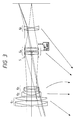
- FIG. 2 illustrates a layout of lenses in an embodiment 2.
- the zoom lens is constructed of, sequentially from the object side, a first lens group G 1 consisting of a negative meniscus lens and a biconvex positive lens, a second lens group G 2 consisting of a cemented lens of a biconcave negative lens and a biconvex positive lens, a third lens group G 3 consisting of a biconcave negative lens, a fourth lens group G 4 consisting of a cemented lens of a biconvex lens and a negative meniscus lens and a fifth lens group G 5 consisting of a cemented lens of a positive lens having a large convexity toward an image and a biconcave lens.
- the embodiment 2 is constructed substantially the same as the embodiment 1. However, the refracting powers and configurations of the respective lens groups are different.
- Table 2 shows values of items in the embodiment 2 according to this invention.
- f is the focal length
- F NO is the F-number
- 2 ⁇ is the field angle.
- the numerals at the left end represent the order from the object side
- r is the radius of curvature of the lens surface
- d is the lens surface separation.
- the second lens group G 2 may be fixed during zooming.
- FIG. 3 illustrates a layout of lenses in an embodiment 3.
- the zoom lens is constructed of, sequentially from the object side, a first positive lens group G 1 consisting of a cemented lens of a negative meniscus lens with its convex surface toward the object and a biconvex positive lens and of a biconvex positive lens, a second negative lens group G 2 consisting of a cemented lens of a negative meniscus lens with its convex surface toward the object and a positive meniscus lens with its convex surface toward the object, a third negative lens group G 3 consisting of a cemented lens of a biconcave negative lens and a biconvex positive lens, a stop S, a fourth positive lens group G 4 consisting of a cemented lens of a biconvex positive lens and a negative meniscus lens with its concave surface toward the object and a fifth negative lens group G 5 consisting of a cemented lens of a biconvex positive lens and a biconcave lens.
- the lens groups move so that the spacing between the first and second lens groups G 1 , G 2 increases; the spacing between the second and third lens groups G 2 , G 3 varies non-linearly; and the spacing between the fourth and fifth lens groups G 4 , G 5 is reduced.
- the fourth lens group G 4 is moved in a direction substantially orthogonal to the optical axis. The vibrations are thus prevented.
- Table 3 shows values of items in the embodiment 1 according to this invention.
- f is the focal length
- F NO is the F-number
- 2 ⁇ is the field angle.
- the numerals at the left end represent the order from the object side
- r is the radius of curvature of the lens surface
- d is the lens surface separation.
- FIG. 4 illustrates a layout of lenses in an embodiment 4.
- the zoom lens is constructed of, sequentially from the object side, a first positive lens group G 1 consisting of a cemented lens of a negative meniscus lens with its convex surface toward the object and a biconvex positive lens and of a biconvex positive lens, a second negative group G 2 consisting of a biconcave negative lens and a positive meniscus lens with its convex surface toward the object, a third negative lens group G 3 consisting of a cemented lens of a biconcave negative lens and a biconvex positive lens, a stop S, a fourth positive lens group G 4 consisting of a cemented lens of a biconvex positive lens and a negative meniscus lens with its concave surface toward the object and of a cemented lens of a biconvex positive lens and a negative meniscus lens with its concave surface toward the object and a fifth negative lens group G 5 consisting of a biconvex positive lens and a bi
- the lens groups move so that the spacing between the first and second lens groups G 1 , G 2 increases; the spacing between the second and third lens groups G 2 , G 3 varies non-linearly; and the spacing between the fourth and fifth lens groups G 4 , G 5 is reduced.
- the fourth lens group G 4 is moved in the direction substantially orthogonal to the optical axis. The vibrations are thus prevented.
- Table 4 shows values of items in the embodiment 4 according to this invention.
- f is the focal length
- F NO is the F-number
- 2 ⁇ is the field angle.
- the numerals at the left end represent the order from the object side
- r is the radius of curvature of the lens surface
- d is the lens surface separation.
- the second lens group may be fixed during zooming.
- the present invention it is possible to the small-sized zoom lens incorporating the vibration-proofing function and exhibiting a high performance.
Landscapes
- Physics & Mathematics (AREA)
- General Physics & Mathematics (AREA)
- Optics & Photonics (AREA)
- Lenses (AREA)
Claims (21)
- Objectif de zoom comprenant, successivement à partir d'un côté objet :caractérisée par :un premier groupe de lentilles (G1) possédant un pouvoir réfringent positif;un second groupe de lentilles (G2) possédant un pouvoir réfringent négatif;un troisième groupe de lentilles (G3) possédant un pouvoir réfringent négatif;un quatrième groupe de lentilles (G4) possédant un pouvoir réfringent positif; etun cinquième groupe de lentilles (G5) possédant un pouvoir réfringent négatif, lesdits groupes de lentilles se déplaçant de telle sorte que, lorsque l'on modifie une puissance de grandissement depuis une extrémité grand-angle à une extrémité téléobjectif, l'espacement entre lesdits premier et second groupes de lentilles (G1; G2) augmente; l'espacement entre lesdits second et troisième groupes de lentilles (G2; G3) varie linéairement ou non-linéairement, et l'espacement entre lesdits quatrième et cinquième groupes de lentilles (G4; G5) diminue,
des moyens de décalage pour empêcher des effets de vibrations, par déplacement de l'un desdits troisième et quatrième groupes de lentilles (G3; G4) dans une direction essentiellement orthogonale à l'axe optique. - Objectif de zoom selon la revendication 1, dans lequel un dispositif (S) de blocage de la lumière parasite, fixé sur l'axe optique, est prévu lorsque ledit troisième groupe de lentilles (G3) se déplace dans la direction essentiellement perpendiculaire à l'axe optique pour empêcher les vibrations.
- Objectif de zoom selon la revendication 1, dans lequel un dispositif (S) d'arrêt de la lumière parasite fixé sur l'axe optique est prévu lorsque ledit quatrième groupe de lentilles (G4) se déplace dans la direction essentiellement orthogonale à l'axe optique pour empêcher les vibrations.
- Objectif de zoom selon la revendication 1, dans lequel ledit quatrième groupe de lentilles (G4) est constitué, successivement à partir du côté objet, par un groupe avant possédant un pouvoir réfringent positif ou négatif et un groupe arrière possédant un pouvoir réfringent positif, ledit groupe arrière étant constitué d'une seule lentille possédant le pouvoir réfringent positif et d'une seule lentille possédant le pouvoir réfringent négatif.
- Objectif de zoom selon la revendication 1, dans lequel ladite lentille de zoom satisfait aux conditions suivantes :
- Objectif de zoom selon la revendication 5, dans lequel ladite lentille de zoom satisfait en outre à la condition suivante :
- Objectif de zoom selon la revendication 6, dans lequel ladite lentille de zoom satisfait à la condition suivante :
- Objectif de zoom selon la revendication 7, dans lequel ladite lentille de zoom satisfait à la condition suivante :
- Objectif de zoom selon la revendication 8, dans lequel ladite lentille de zoom satisfait à la condition suivante :
n : indice de réfraction moyen des lentilles constituant ledit troisième groupe de lentilles (G3), etν : nombre d'Abbe moyen en rapport avec la raie d moyenne des lentilles constituant ledit troisième groupe de lentilles (G3), etl'indice de réfraction moyen n desdits troisièmes groupes de lentilles (G3) est obtenu au moyen de la formule suivante : - Objectif de zoom selon la revendication 9, dans lequel ladite lentille de zoom satisfait à la condition suivante :
- Objectif de zoom selon la revendication 5, dans lequel un dispositif (S) d'arrêt de blocage de la lumière parasite fixé sur l'axe optique est prévu lorsque ledit troisième groupe de lentilles (G3) se déplace dans la direction sensiblement perpendiculaire à l'axe optique pour empêcher les vibrations.
- Objectif de zoom selon la revendication 1, dans lequel ladite lentille de zoom satisfait aux conditions suivantes :
- Objectif de zoom selon la revendication 12, dans lequel un dispositif d'arrêt de la lumière parasite fixé sur l'axe optique est prévu lorsque ledit quatrième groupe de lentilles (G4) se déplace dans la direction sensiblement perpendiculaire à l'axe optique pour empêcher les vibrations.
- Objectif de zoom selon la revendication 12, dans lequel ledit quatrième groupe de lentilles (G4) est constitué, successivement à partir du côté objet, par un groupe avant possédant un pouvoir réfringent positif ou négatif et un groupe arrière possédant un pouvoir réfringent positif, ledit groupe arrière étant constitué d'une seule lentille possédant le pouvoir réfringent positif et d'une seule lentille possédant le pouvoir réfringent négatif.
- Objectif de zoom selon la revendication 14, dans lequel ledit groupe arrière est constitué, successivement à partir du côté objet, par une seule lentille convergente et une seule lentille divergente.
- Objectif de zoom selon la revendication 15, dans lequel ladite lentille de zoom satisfait à la condition suivante :f4 : distance focale dudit quatrième groupe de lentilles (G4), etf4R : distance focale dudit groupe arrière.
- Objectif de zoom selon la revendication 16, dans lequel ladite lentille de zoom satisfait à la condition suivante :N+ : indice de réfraction de la lentille convergente unique, etN-: indice de réfraction de la lentille divergente unique constituant ledit groupe arrière.
- Objectif de zoom selon la revendication 5, dans lequel ladite lentille de zoom est constituée sur la base des données suivantes :
f = 82 - 196 FNO = 4,6 - 5,7 2ω = 29,66 - 12,16° r d ν n 1 53,631 2,20 23,0 1,86074 2 39,941 0,50 3 42,000 6,00 69,9 1,51860 4 -253,597 (d4 = variable) 5 -46,982 1,50 47,1 1,67003 6 37,449 3,00 27,6 1,75520 7 -154,003 (d7 = variable) 8 -250,166 2,00 47,5 1,78797 9 78,415 (d9 = variable) 10 152,812 3,00 46,4 1,58267 11 -37,057 0,20 12 50,036 4,50 60,7 1,56384 13 -31,136 1,70 25,5 1,80458 14 -354,680 (d14 = variable) 15 -488,183 3,00 26,1 1,78470 16 -46,681 2,07 17 -50,713 1,50 53,7 1,69350 18 35,916 (d18 = variable) (Séparation variable à puissance variable) f 82,0000 135,0000 196,0000 D0 ∞ ∞ ∞ d4 2,1562 23,7506 39,4991 d7 4,1898 2,7190 8,8577 d9 24,9438 14,6750 2,8315 d14 22,0952 12,2404 2,1968 d18 43,0664 64,6608 80,4093 f1 = 111,021, fW = 82, fT = 196f2 = -145,113f3 = -75,564DW3-4 = 24,9438βW3 = 0,2444, βT3 = -1,8630R31 = -250,166(1) f1 / (fW · fT)1/2 = 0,87573(2) f2 / f3 = 1,92034(3) | f3 | / fW = 0,9215(4) DW3-4 / fW = 0,304193(5) βT3 / βW3 = 7,623(6) n = 1,78797(7) ν = 47,5(8) R31 = -250,166(Données de protection contre les vibrations) Extrémité grand-angle Extrémité téléobjectif Distance de déplacement (mm) du 3-ème groupe de lentilles dans une direction perpendiculaire à l'axe optique 0,198 0,350 Distance de déplacement de l'image (mm) 0,2 0,5 DW3-4 : espacement entre lesdits troisième et quatrième groupes de lentilles sur l'extrémité grand-angle,βW3 : grandissement d'utilisation dudit troisième groupe de lentilles sur l'extrémité grand-angle,βT3 : grandissement d'utilisation dudit troisième groupe de lentilles sur l'extrémité téléobjectif,n : indice de réfraction moyen des lentilles constituant ledit troisième groupe de lentilles (G3), etν : nombre d'Abbe moyen en rapport avec la raie d moyenne des lentilles constituant ledit troisième groupe de lentilles, etl'indice de réfraction moyenn dudit troisième groupe de lentilles est obtenu au moyen de la formule suivante : - Objectif de zoom selon la revendication 5, dans lequel ladite lentille de zoom est constituée sur la base des données suivantes :
f = 82 - 196 FNO = 4,62 - 5,7 2ω = 29,24 - 12,08° r d ν n 1 53,993 2,20 25,5 1,80458 2 37,137 0,50 3 37,749 7,00 64,1 1,51680 4 -228,729 (d4 = variable) 5 -42,349 1,50 42,0 1,66755 6 32,372 3,00 27,6 1,75520 7 -105,299 (d7 = variable) 8 -300,511 2,00 47,5 1,78797 9 68,734 (d9 = variable) 10 474,746 3,00 46,4 1,58267 11 -35,274 0,50 12 45,251 4,50 60,7 1,56384 13 -32,297 1,70 25,5 1,80458 14 -242,346 (d14 = variable) 15 ∞ 4,00 26,1 1,78470 16 -24,282 1,50 38,8 1,67163 17 -28,801 (d17 = variable) (Séparation variable à puissance variable) f 82,0000 135,0000 196,0000 D0 ∞ ∞ ∞ d4 2,8064 24,7099 39,4550 d7 2,9810 0,5461 7,4257 d9 24,5298 14,9373 2,7893 d14 23,3891 13,5130 3,5363 d17 40,6047 62,50817 77,7533 f1 = 107,913, fW = 82, fT = 196f2 = -179,085f3 = -70,823DW3-4 = 24,5298βW3 = -0,4285, βT3 = -3,4888R31 = -300,511(1) f1 / (fW · fT)1/2 = 0,85121(2) f2 / f3 = 2,52863(3) | f3 | / fW = 0,8637(4) DW3-4 / fW = 0,299144(5) βT3 / βW3 = 8,1419(6) n = 1,78797(7) ν = 47,5(8) R31 = -300,511(Données de protection contre les vibrations) Extrémité grand-angle Extrémité téléobjectif Distance de déplacement (mm) du 3-ème groupe de lentilles dans une direction perpendiculaire à l'axe optique 0,188 0,341 Distance de déplacement de l'image (mm) 0,2 0,5 DW3-4 : espacement entre lesdits troisième et quatrième groupes de lentilles sur l'extrémité grand-angle,βW3 : grandissement d'utilisation dudit troisième groupe de lentilles sur l'extrémité grand-angle,βT3 : grandissement d'utilisation dudit troisième groupe de lentilles sur l'extrémité téléobjectif,n : indice de réfraction moyen des lentilles constituant ledit troisième groupe de lentilles (G3), etν : nombre d'Abbe moyen en rapport avec la raie d moyenne des lentilles constituant ledit troisième groupe de lentilles (G3), etl'indice de réfraction moyenn desdits troisièmes groupes de lentilles est obtenu au moyen de la formule suivante : - Objectif de zoom selon la revendication 12, dans lequel ladite lentille de zoom est constituée sur la base des données suivantes :
f = 76,5 - 292 FNO = 4,62 - 5,77 2ω = 32,6° - 8,2° r d ν n 1 280,061 2,00 40,9 1,79631 2 77,586 5,30 82,6 1,49782 3 -428,027 0,20 4 87,627 6,50 70,1 1,51860 5 -427,957 (d5 = variable) 6 -142,978 1,70 45,9 1,54814 7 22,745 5,50 36,3 1,62004 8 104,648 (d8 = variable) 9 -52,404 1,50 47,5 1,78797 10 56,961 3,60 33,8 1,64831 11 -75,627 (d11 = variable) 12 152,933 3,80 48,1 1,71700 13 -43,246 1,60 23,0 1,86074 14 -83,641 0,50 15 71,466 4,50 57,0 1,62280 16 -42,561 1,60 33,9 1,80384 17 -150,924 (d17 = variable) 18 156,427 3,70 33,9 1,80384 19 -36,315 1,50 49,4 1,77279 20 33,124 (d20 = variable) (Séparation variable à puissance variable) f 76,4987 150,0000 291,9999 D0 ∞ ∞ ∞ d5 2,0535 25,9285 61,4300 d8 4,1341 20,1309 20,1276 d11 55,3562 23,7336 9,2402 d17 30,1656 21,9163 0,9115 d20 41,5180 65,3932 100,8948 f1 = 137,3, fW = 76,5,fT = 292f4 = -47,503, f5 = -58,888f4R = -102,673DW3-4 = 55,3562N+ = 1,62280, N- = 1,80384(1) f1 / (fW . fT)1/2 = 0,918646(9) DW3-4 / fW = 0,72361(10) f4 / |f5| = 0,806667(11) f4R / F4 = 2,1614(12) (N+ + N-) / 2 = 1,713320(Données de protection contre les vibrations) Extrémité grand-angle Extrémité téléobjectif Distance de déplacement (mm) du 3-ème groupe de lentilles dans une direction perpendiculaire à l'axe optique 0,11295 0,38273 Distance de déplacement de l'image (mm) 0,25 1 f4 : distance focale dudit quatrième groupe de lentilles G4, etf4R : distance focale dudit groupe arrière.N+ : indice de réfraction de la lentille convergente unique, etN-: indice de réfraction de la lentille divergente unique constituant ledit groupe arrière. - Objectif de zoom selon la revendication 12, dans lequel ladite lentille de zoom est constituée sur la base des données suivantes :
f = 76,5 - 292 FNO = 4,71 - 5,87 2ω = 32,4° - 8,2° r d ν n 1 249,519 2,00 40,9 1,79631 2 76,291 7,50 82,6 1,49782 3 -357,836 0,50 4 95,779 6,00 70,1 1,51860 5 -564,320 (d5 = variable) 6 -133,390 1,70 45,1 1,74400 7 45,598 1.80 8 38,299 3,80 33,8 1,64831 9 404,759 (d9 = variable) 10 -61,368 1,50 44,7 1,80218 11 38,992 5,00 33,8 1,64831 12 -82,355 (d12 = variable) 13 148,526 4,30 46,8 1,76684 14 -44,204 1,60 23,8 1,84666 15 -86,959 0,20 16 79,739 4,50 60,3 1,62041 17 -38,089 1,60 33,9 1,80384 18 -150,489 (d18 = variable) 19 751,594 3,00 23,8 1,84666 20 -88,822 4,30 21 -97,367 1,50 46,4 1,80411 22 36,532 (d22 = variable) (Séparation variable à puissance variable) f 76,4992 150,0000 291,9988 D0 ∞ ∞ ∞ d5 2,4300 28,6704 60,1162 d9 2,9542 15,5332 13,9733 d12 53,6639 24,2782 1,3195 d18 24,7698 17,4831 1,5011 d22 44,8033 68,8967 109,3968 f1 = 143,0, fW = 76,5, fT = 292f4 = 47,586, f5 = -55,134f4R = 120,768DW3-4 = 53,6639N+ = 1,62280, N- = 1,80384(1) f1 / (fW · fT)1/2 = 0,956784(9) DW3-4 / fW = 0,701489(10) f4 / |f5| = 0,863097(11) f4R / f4 = 2,537889(12) (N+ + N-) / 2 = 1,713320(Données de protection contre les vibrations) Extrémité grand-angle Extrémité téléobjectif Distance de déplacement (mm) du 4-ème groupe de lentilles dans une direction perpendiculaire à l'axe optique 0,10737 0,31141 Distance de déplacement de l'image (mm) 0,25 1 f4 : distance focale dudit quatrième groupe de lentilles G4, etf4R : distance focale dudit groupe arrière.N+ : indice de réfraction de la lentille convergente unique, etN- : indice de réfraction de la lentille divergente unique constituant ledit groupe arrière.
Applications Claiming Priority (4)
| Application Number | Priority Date | Filing Date | Title |
|---|---|---|---|
| JP4275621A JPH06123836A (ja) | 1992-10-14 | 1992-10-14 | 防振機能を備えたズームレンズ |
| JP275621/92 | 1992-10-14 | ||
| JP4275626A JPH06130330A (ja) | 1992-10-14 | 1992-10-14 | 防振機能を備えたズームレンズ |
| JP275626/92 | 1992-10-14 |
Publications (2)
| Publication Number | Publication Date |
|---|---|
| EP0592916A1 EP0592916A1 (fr) | 1994-04-20 |
| EP0592916B1 true EP0592916B1 (fr) | 1998-01-21 |
Family
ID=26551549
Family Applications (1)
| Application Number | Title | Priority Date | Filing Date |
|---|---|---|---|
| EP93116020A Expired - Lifetime EP0592916B1 (fr) | 1992-10-14 | 1993-10-04 | Objectif de zoom avec dispositif anti-vibration |
Country Status (3)
| Country | Link |
|---|---|
| US (1) | US5502594A (fr) |
| EP (1) | EP0592916B1 (fr) |
| DE (1) | DE69316510T2 (fr) |
Families Citing this family (25)
| Publication number | Priority date | Publication date | Assignee | Title |
|---|---|---|---|---|
| JPH0829738A (ja) * | 1994-07-18 | 1996-02-02 | Nikon Corp | 防振ズームレンズ |
| JPH0868941A (ja) * | 1994-08-30 | 1996-03-12 | Nikon Corp | 高倍率ズームレンズ |
| US5790309A (en) * | 1994-09-29 | 1998-08-04 | Nikon Corporation | Zoom lens system capable of shifting an image and compensating back focus variation |
| US5831768A (en) * | 1994-10-06 | 1998-11-03 | Nikon Corporation | Zoom lens capable of shifting an image |
| JP3365087B2 (ja) * | 1994-10-14 | 2003-01-08 | ミノルタ株式会社 | 手ぶれ補正機能を有する光学系 |
| JPH08278445A (ja) * | 1995-04-04 | 1996-10-22 | Nikon Corp | 防振機能を備えたズームレンズ |
| JP3412964B2 (ja) * | 1995-05-10 | 2003-06-03 | キヤノン株式会社 | 防振機能を有した光学系 |
| US6266189B1 (en) * | 1996-02-23 | 2001-07-24 | Minolta Co., Ltd. | Zoom lens system having an image blur compensating function |
| JP3417192B2 (ja) * | 1996-02-27 | 2003-06-16 | ミノルタ株式会社 | 手ぶれ補正機能を有する光学系及びズームレンズ |
| US5841588A (en) * | 1996-03-06 | 1998-11-24 | Nikon Corporation | Zoom lens system with vibration reduction means |
| US6025962A (en) * | 1996-09-12 | 2000-02-15 | Nikon Corporation | Zoom lens with an anti-vibration function |
| US6061180A (en) * | 1996-10-29 | 2000-05-09 | Canon Kabushiki Kaisha | Zoom lens |
| JPH11194270A (ja) * | 1998-01-05 | 1999-07-21 | Asahi Optical Co Ltd | 防振機能を有するズーム撮影光学系 |
| JPH11258504A (ja) * | 1998-03-12 | 1999-09-24 | Nikon Corp | 防振ズームレンズ |
| US6392816B1 (en) * | 1999-10-29 | 2002-05-21 | Canon Kabushiki Kaisha | Variable magnification optical system and optical apparatus having the same |
| JP4374853B2 (ja) * | 2002-12-27 | 2009-12-02 | 株式会社ニコン | 防振ズームレンズ |
| JP4210272B2 (ja) * | 2005-06-29 | 2009-01-14 | フジノン株式会社 | 防振ズームレンズ及びこれを備えたカメラ |
| EP2045637B1 (fr) | 2007-10-02 | 2019-07-10 | Nikon Corporation | Système de lentille de zoom |
| US8194317B2 (en) * | 2008-04-02 | 2012-06-05 | Panasonic Corporation | Zoom lens system, interchangeable lens apparatus and camera system |
| CN102597844B (zh) * | 2010-02-10 | 2014-12-24 | 松下电器产业株式会社 | 变焦透镜系统、可更换镜头装置及相机系统 |
| CN102636865B (zh) * | 2011-02-09 | 2015-01-21 | 株式会社理光 | 变焦镜头、照相机、信息装置以及携带型信息终端装置 |
| JP2012242690A (ja) | 2011-05-20 | 2012-12-10 | Sony Corp | インナーフォーカス式レンズ |
| US9313384B2 (en) | 2012-12-07 | 2016-04-12 | Samsung Electronics Co., Ltd. | Zoom lens having vibration prevention function |
| WO2015146175A1 (fr) * | 2014-03-27 | 2015-10-01 | 株式会社ニコン | Objectif à focale variable, dispositif d'imagerie, et procédé de production d'objectif à focale variable |
| WO2016121939A1 (fr) * | 2015-01-30 | 2016-08-04 | 株式会社ニコン | Système optique à grossissement variable ainsi que procédé de fabrication de celui-ci, et appareil optique |
Family Cites Families (9)
| Publication number | Priority date | Publication date | Assignee | Title |
|---|---|---|---|---|
| JPS6041012A (ja) * | 1983-08-16 | 1985-03-04 | Canon Inc | ズ−ムレンズ鏡胴 |
| JPH0625826B2 (ja) * | 1984-02-21 | 1994-04-06 | トキナー光学株式会社 | コンパクトな高倍率ズ−ムレンズ |
| JP2560377B2 (ja) * | 1988-01-26 | 1996-12-04 | キヤノン株式会社 | 防振機能を有した変倍光学系 |
| JP2621280B2 (ja) * | 1988-01-26 | 1997-06-18 | キヤノン株式会社 | 防振機能を有した変倍光学系 |
| JP2605326B2 (ja) * | 1988-01-26 | 1997-04-30 | キヤノン株式会社 | 防振機能を有した変倍光学系 |
| JPH01284823A (ja) * | 1988-05-12 | 1989-11-16 | Canon Inc | 防振機能を有した変倍光学系 |
| US5040881A (en) * | 1988-05-12 | 1991-08-20 | Canon Kabushiki Kaisha | Image stabilization lens system |
| JP2918115B2 (ja) * | 1988-09-30 | 1999-07-12 | キヤノン株式会社 | 防振機能を有した変倍光学系 |
| JPH05273467A (ja) * | 1992-03-25 | 1993-10-22 | Nikon Corp | 内焦方式のズームレンズ |
-
1993
- 1993-10-04 EP EP93116020A patent/EP0592916B1/fr not_active Expired - Lifetime
- 1993-10-04 DE DE69316510T patent/DE69316510T2/de not_active Expired - Fee Related
- 1993-10-07 US US08/132,909 patent/US5502594A/en not_active Expired - Lifetime
Also Published As
| Publication number | Publication date |
|---|---|
| EP0592916A1 (fr) | 1994-04-20 |
| DE69316510T2 (de) | 1998-05-28 |
| US5502594A (en) | 1996-03-26 |
| DE69316510D1 (de) | 1998-02-26 |
Similar Documents
| Publication | Publication Date | Title |
|---|---|---|
| EP0592916B1 (fr) | Objectif de zoom avec dispositif anti-vibration | |
| US6320698B1 (en) | Zoom lens with vibration reduction function | |
| JP3371917B2 (ja) | 防振機能を備えたズームレンズ | |
| US5585966A (en) | Zoom lens with vibration reduction function | |
| US5126883A (en) | Telephoto zoom lens | |
| US5731897A (en) | Zoom lens with an image stabilizing function | |
| JP3395169B2 (ja) | 防振機能を備えたズームレンズ | |
| JPH08278445A (ja) | 防振機能を備えたズームレンズ | |
| JP3072815B2 (ja) | 変倍光学系 | |
| KR20050035541A (ko) | 손 떨림 보정 기능 탑재 줌 렌즈 | |
| US5757555A (en) | Internal focusing type telephoto lens | |
| JPH0792431A (ja) | 防振機能を備えたズームレンズ | |
| JP3365835B2 (ja) | コンパクトな3群ズームレンズ | |
| JPH08327897A (ja) | 内焦式望遠レンズ | |
| US6278559B1 (en) | Zoom lens for television camera | |
| JPH11258504A (ja) | 防振ズームレンズ | |
| JP3536128B2 (ja) | 防振機能を備えたズームレンズ | |
| JPH07120678A (ja) | 3群ズームレンズのフォーカシング方式 | |
| JPH0727975A (ja) | 防振機能を備えたリアコンバージョンレンズ | |
| US5786945A (en) | Zoom lens system | |
| US6661584B2 (en) | Zoom lens and camera having the zoom lens | |
| JPH06130330A (ja) | 防振機能を備えたズームレンズ | |
| JP3268824B2 (ja) | 小型の2群ズームレンズ | |
| JPH06123836A (ja) | 防振機能を備えたズームレンズ | |
| US6324017B1 (en) | Zoom lens system and a focusing method thereof |
Legal Events
| Date | Code | Title | Description |
|---|---|---|---|
| PUAI | Public reference made under article 153(3) epc to a published international application that has entered the european phase |
Free format text: ORIGINAL CODE: 0009012 |
|
| AK | Designated contracting states |
Kind code of ref document: A1 Designated state(s): DE FR |
|
| 17P | Request for examination filed |
Effective date: 19940810 |
|
| GRAG | Despatch of communication of intention to grant |
Free format text: ORIGINAL CODE: EPIDOS AGRA |
|
| 17Q | First examination report despatched |
Effective date: 19961217 |
|
| GRAH | Despatch of communication of intention to grant a patent |
Free format text: ORIGINAL CODE: EPIDOS IGRA |
|
| GRAH | Despatch of communication of intention to grant a patent |
Free format text: ORIGINAL CODE: EPIDOS IGRA |
|
| GRAH | Despatch of communication of intention to grant a patent |
Free format text: ORIGINAL CODE: EPIDOS IGRA |
|
| GRAA | (expected) grant |
Free format text: ORIGINAL CODE: 0009210 |
|
| AK | Designated contracting states |
Kind code of ref document: B1 Designated state(s): DE FR |
|
| REF | Corresponds to: |
Ref document number: 69316510 Country of ref document: DE Date of ref document: 19980226 |
|
| ET | Fr: translation filed | ||
| PLBE | No opposition filed within time limit |
Free format text: ORIGINAL CODE: 0009261 |
|
| STAA | Information on the status of an ep patent application or granted ep patent |
Free format text: STATUS: NO OPPOSITION FILED WITHIN TIME LIMIT |
|
| 26N | No opposition filed | ||
| PGFP | Annual fee paid to national office [announced via postgrant information from national office to epo] |
Ref country code: FR Payment date: 19990930 Year of fee payment: 7 |
|
| PGFP | Annual fee paid to national office [announced via postgrant information from national office to epo] |
Ref country code: DE Payment date: 19991028 Year of fee payment: 7 |
|
| PG25 | Lapsed in a contracting state [announced via postgrant information from national office to epo] |
Ref country code: FR Free format text: LAPSE BECAUSE OF NON-PAYMENT OF DUE FEES Effective date: 20010629 |
|
| PG25 | Lapsed in a contracting state [announced via postgrant information from national office to epo] |
Ref country code: DE Free format text: LAPSE BECAUSE OF NON-PAYMENT OF DUE FEES Effective date: 20010703 |
|
| REG | Reference to a national code |
Ref country code: FR Ref legal event code: ST |