EP0593353A1 - Verbindungsflansch für die Klimaanlage eines Fahrzeuges - Google Patents
Verbindungsflansch für die Klimaanlage eines Fahrzeuges Download PDFInfo
- Publication number
- EP0593353A1 EP0593353A1 EP93402504A EP93402504A EP0593353A1 EP 0593353 A1 EP0593353 A1 EP 0593353A1 EP 93402504 A EP93402504 A EP 93402504A EP 93402504 A EP93402504 A EP 93402504A EP 0593353 A1 EP0593353 A1 EP 0593353A1
- Authority
- EP
- European Patent Office
- Prior art keywords
- flange
- semi
- openings
- zones
- pipes
- Prior art date
- Legal status (The legal status is an assumption and is not a legal conclusion. Google has not performed a legal analysis and makes no representation as to the accuracy of the status listed.)
- Granted
Links
Images
Classifications
-
- B—PERFORMING OPERATIONS; TRANSPORTING
- B60—VEHICLES IN GENERAL
- B60H—ARRANGEMENTS OF HEATING, COOLING, VENTILATING OR OTHER AIR-TREATING DEVICES SPECIALLY ADAPTED FOR PASSENGER OR GOODS SPACES OF VEHICLES
- B60H1/00—Heating, cooling or ventilating devices
- B60H1/00507—Details, e.g. mounting arrangements, desaeration devices
- B60H1/00557—Details of ducts or cables
- B60H1/00571—Details of ducts or cables of liquid ducts, e.g. for coolant liquids or refrigerants
-
- F—MECHANICAL ENGINEERING; LIGHTING; HEATING; WEAPONS; BLASTING
- F16—ENGINEERING ELEMENTS AND UNITS; GENERAL MEASURES FOR PRODUCING AND MAINTAINING EFFECTIVE FUNCTIONING OF MACHINES OR INSTALLATIONS; THERMAL INSULATION IN GENERAL
- F16L—PIPES; JOINTS OR FITTINGS FOR PIPES; SUPPORTS FOR PIPES, CABLES OR PROTECTIVE TUBING; MEANS FOR THERMAL INSULATION IN GENERAL
- F16L3/00—Supports for pipes, cables or protective tubing, e.g. hangers, holders, clamps, cleats, clips, brackets
- F16L3/22—Supports for pipes, cables or protective tubing, e.g. hangers, holders, clamps, cleats, clips, brackets specially adapted for supporting a number of parallel pipes at intervals
- F16L3/223—Supports for pipes, cables or protective tubing, e.g. hangers, holders, clamps, cleats, clips, brackets specially adapted for supporting a number of parallel pipes at intervals each support having one transverse base for supporting the pipes
-
- F—MECHANICAL ENGINEERING; LIGHTING; HEATING; WEAPONS; BLASTING
- F16—ENGINEERING ELEMENTS AND UNITS; GENERAL MEASURES FOR PRODUCING AND MAINTAINING EFFECTIVE FUNCTIONING OF MACHINES OR INSTALLATIONS; THERMAL INSULATION IN GENERAL
- F16L—PIPES; JOINTS OR FITTINGS FOR PIPES; SUPPORTS FOR PIPES, CABLES OR PROTECTIVE TUBING; MEANS FOR THERMAL INSULATION IN GENERAL
- F16L39/00—Joints or fittings for double-walled or multi-channel pipes or pipe assemblies
-
- F—MECHANICAL ENGINEERING; LIGHTING; HEATING; WEAPONS; BLASTING
- F25—REFRIGERATION OR COOLING; COMBINED HEATING AND REFRIGERATION SYSTEMS; HEAT PUMP SYSTEMS; MANUFACTURE OR STORAGE OF ICE; LIQUEFACTION SOLIDIFICATION OF GASES
- F25B—REFRIGERATION MACHINES, PLANTS OR SYSTEMS; COMBINED HEATING AND REFRIGERATION SYSTEMS; HEAT PUMP SYSTEMS
- F25B41/00—Fluid-circulation arrangements
- F25B41/40—Fluid line arrangements
Definitions
- the invention relates to a flange for the simultaneous connection to an element of a fluid circuit, in particular in a motor vehicle air conditioning installation, of the free ends of two pipes which extend substantially parallel to one another. from these ends and are connected to each other at their opposite ends, the flange being adapted to bear on annular beads presented by said free ends to compress seals between them and surfaces for receiving said element, under the action of clamping means urging the flange towards said element, the flange having the shape of an elongated plate traversed in its thickness by two openings, one of which has the shape of a notch opening into one of its ends , suitable for respectively receiving the two tubes and comprising substantially semi-circular regions adapted to the circumference of the tubes, l adite notch forming, between the end of the flange and the semi-circular region, a slot with parallel edges substantially tangent to the latter.
- Such a flange is described in FR-A-2 668 242.
- This known flange is intended to connect to a regulator of an air conditioning installation the free ends of the inlet and outlet pipes of an evaporator, which are connected to each other. their ends opposite by this evaporator and which are arranged one above the other.
- the two openings are notches opening respectively in its opposite ends.
- the edges of the slots formed by the notches are inclined relative to the plane containing the axes of the semi-circular bottoms.
- the object of the invention is to obtain the same result in an even safer manner, and this whatever the relative arrangement of the two pipes.
- the invention provides in particular that, in a flange of the kind defined in the introduction, the second opening is surrounded by the material of the flange over its entire periphery and has an enlarged region suitable for allowing the passage of the bead of the corresponding tubing and connecting directly to the substantially semicircular region.
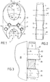
- the flange illustrated has the shape of a plate 1 longer than wide, traversed in its thickness by two openings 2 and 3.
- the opening 2 is a notch having a semi-circular bottom 4 connecting to the two parallel edges 5 of a slot which opens into one of the ends of the plate 1.
- the opening 3 has a closed profile composed of two arcs of a circle, namely an arc 6 very slightly greater than a semicircle and an arc 7 substantially greater than a half -circle, the radius R3 of the arc 7 being greater than the radius R2 of the arc 6.
- the axes A1, A2 and A3 of the arcs 4, 6 and 7 respectively are perpendicular to the general plane of the plate 1 and mutually aligned, in this order, in a longitudinal plane of symmetry thereof.
- the flange 1 is intended to cooperate with two pipes 21 and 22 respectively engaging in the openings 2 and 3 and extending normally along the axes A1 and A2, the radii of these pipes being slightly less than the radius R1 of the arc 4 and radius R2 of arc 6 respectively.
- These pipes, the center distance of which therefore corresponds to that of the arcs 4 and 6, are provided at their free ends with beads 23 and 24, the first of which has a radius greater than the radius R1 and the second of which has a radius greater than the radius R2 and less than the radius R3.
- Clamping screws cooperating with threaded holes 8, with axes also perpendicular to the general plane of the plate, make it possible to apply that of the faces of the flange facing the beads against them so as to compress seals d between the beads and a surface for receiving the element 25 to be connected to the pipes.
- the zones 11, adjacent to the semicircular bottom 4 of the notch 2 and the zones 12, adjacent to the semicircular region 6 of the opening 3, on the two faces of the flange are portions of spherical surfaces, the centers of the spheres to which belong the zones 11 being located on the axis A1 and the centers of the spheres to which the zones 12 belong being located on the axis A2. These portions of spherical surfaces extend along the edges 5 of the notch, to the end of the flange into which the latter opens, and around the arc-shaped region 7 of the opening 3.
- the flange is symmetrical on the one hand with respect to the plane containing axes A1, A2 and A3, on the other hand with respect to a plane perpendicular to these axes, and can be mounted indifferently in two positions in which its two faces respectively come into contact with the beads of the pipes.
- the spherical shape of zones 11 and 12 gives them a double convexity in the longitudinal direction and in the lateral direction of the flange, which adjusts the position of their points of contact with the beads so as to exert on them a substantially centered thrust on the axes 28 and 29 of the pipes when these the latter do not have exactly the same orientation as the axes A1 and A2.
- the convexity in the longitudinal direction occurs when the misalignment is due to the fact that the two beads are not exactly in the same plane, situation illustrated in FIG. 3.
- the convexity in the lateral direction plays its role when the axes of the two pipes do not are not perfectly coplanar.
Landscapes
- Engineering & Computer Science (AREA)
- General Engineering & Computer Science (AREA)
- Mechanical Engineering (AREA)
- Physics & Mathematics (AREA)
- Thermal Sciences (AREA)
- Quick-Acting Or Multi-Walled Pipe Joints (AREA)
- Air-Conditioning For Vehicles (AREA)
- Heat-Exchange Devices With Radiators And Conduit Assemblies (AREA)
- Joints Allowing Movement (AREA)
- Supports For Pipes And Cables (AREA)
Applications Claiming Priority (2)
| Application Number | Priority Date | Filing Date | Title |
|---|---|---|---|
| FR9212160A FR2697890B1 (fr) | 1992-10-12 | 1992-10-12 | Bride de raccordement pour installation de climatisation de véhicule automobile. |
| FR9212160 | 1992-10-12 |
Publications (2)
| Publication Number | Publication Date |
|---|---|
| EP0593353A1 true EP0593353A1 (de) | 1994-04-20 |
| EP0593353B1 EP0593353B1 (de) | 1996-08-21 |
Family
ID=9434430
Family Applications (1)
| Application Number | Title | Priority Date | Filing Date |
|---|---|---|---|
| EP93402504A Expired - Lifetime EP0593353B1 (de) | 1992-10-12 | 1993-10-11 | Verbindungsflansch für die Klimaanlage eines Fahrzeuges |
Country Status (6)
| Country | Link |
|---|---|
| US (1) | US5387014A (de) |
| EP (1) | EP0593353B1 (de) |
| JP (1) | JPH06211033A (de) |
| DE (1) | DE69304170T2 (de) |
| ES (1) | ES2092261T3 (de) |
| FR (1) | FR2697890B1 (de) |
Cited By (3)
| Publication number | Priority date | Publication date | Assignee | Title |
|---|---|---|---|---|
| GB2276695B (en) * | 1993-03-29 | 1997-07-16 | Guido Juergen Dipl Ing | Injection line assembly |
| US6776421B2 (en) * | 2000-02-10 | 2004-08-17 | Delphi Technologies, Inc. | Fluid sealing system |
| EP2322368A3 (de) * | 2009-11-17 | 2011-09-21 | Behr GmbH & Co. KG | Verbindungsvorrichtung |
Families Citing this family (19)
| Publication number | Priority date | Publication date | Assignee | Title |
|---|---|---|---|---|
| DE4413488A1 (de) * | 1994-04-19 | 1995-10-26 | Leybold Ag | Vakuumdichte Verbindung |
| JPH0875074A (ja) * | 1994-09-07 | 1996-03-19 | Kayaba Ind Co Ltd | ポンプ用サクションコネクター |
| US5467611A (en) * | 1994-11-07 | 1995-11-21 | General Motors Corporation | Two plate TXV block connector for automotive A/C system with common bolts and independently attachable sides |
| FR2757613B1 (fr) * | 1996-12-23 | 1999-03-05 | Valeo Climatisation | Dispositif de raccordement de tubulures a un bloc detendeur d'un circuit de climatisation, en particulier de vehicule automobile |
| DE29718382U1 (de) * | 1997-10-16 | 1997-12-11 | Aeroquip-Vickers International GmbH, 76532 Baden-Baden | Flanschvorrichtung |
| US6431614B1 (en) | 1999-10-29 | 2002-08-13 | Automotive Fluid Systems, Inc. | Anti-cantilever fastener for a conduit connection |
| US6908117B1 (en) | 2000-10-06 | 2005-06-21 | Hutchinson Fts, Inc. | Block-conduit connection alignment device |
| US6682100B2 (en) * | 2001-02-15 | 2004-01-27 | Parker-Hannifin Corporation | Connection block with clip |
| DE10141944A1 (de) * | 2001-08-28 | 2003-04-03 | Bayerische Motoren Werke Ag | Montageflansch für Rohrverbindungen |
| US6866300B2 (en) * | 2002-10-29 | 2005-03-15 | Calsonickansei North America, Inc. | Dual flange for a tube joint assembly |
| US7032500B1 (en) * | 2004-08-27 | 2006-04-25 | Dana Corporation | Single point steering gear hydraulic connection |
| US20060130643A1 (en) * | 2004-12-22 | 2006-06-22 | Lucas Frank | Hydraulic actuator with internal channels and quick connections |
| WO2007124714A1 (de) * | 2006-05-01 | 2007-11-08 | Luk Lamellen Und Kupplungsbau Beteiligungs Kg | Freilauf mit dämpfung |
| JP2007315482A (ja) * | 2006-05-25 | 2007-12-06 | Calsonic Kansei Corp | 配管継手 |
| US7819436B2 (en) * | 2007-06-27 | 2010-10-26 | Yh America, Inc. | Endformed tubular assembly |
| US7870655B2 (en) * | 2007-06-27 | 2011-01-18 | Yh America, Inc. | Process of endforming a tubular assembly |
| US7837041B2 (en) * | 2007-06-27 | 2010-11-23 | Yh America, Inc. | Method of determining the robustness of endformed tubular assembly and predicting the performance of such assembly in high pressure applications |
| US9114687B2 (en) * | 2013-03-15 | 2015-08-25 | Denso International America, Inc. | AC dual joint-block design |
| DE102014103314B4 (de) * | 2014-03-12 | 2018-07-12 | Tenneco Gmbh | Abgasrohrflansch, Gruppenflansch und Abgasanlage |
Citations (5)
| Publication number | Priority date | Publication date | Assignee | Title |
|---|---|---|---|---|
| US3869153A (en) * | 1974-07-22 | 1975-03-04 | Gen Motors Corp | Double tube mounting assembly |
| US3944264A (en) * | 1975-01-06 | 1976-03-16 | Westinghouse Air Brake Company | Pipe bracket |
| US4163372A (en) * | 1977-10-25 | 1979-08-07 | Carrier Corporation | Capillary retainer clip |
| GB2068490A (en) * | 1980-01-31 | 1981-08-12 | Gewerk Eisenhuette Westfalia | Hydraulic coupling device |
| DE3011226A1 (de) * | 1980-03-22 | 1981-10-01 | Pohle + Rehling Gmbh, 4353 Oer-Erkenschwick | Steckkupplung fuer mehradrige schlauchleitungen |
Family Cites Families (11)
| Publication number | Priority date | Publication date | Assignee | Title |
|---|---|---|---|---|
| DE304149C (de) * | ||||
| CH69225A (de) * | 1914-06-11 | 1915-06-01 | Schmidt Sche Heissdampf | Verbindungsglied zum Überführen mehrerer Rohre in eines, insbesondere von Rohren für Überhitzer |
| US1989649A (en) * | 1932-04-18 | 1935-01-29 | Oxweld Acetylene Co | Blowpipe |
| CH179221A (de) * | 1934-11-14 | 1935-08-31 | Helbock Karl | Einrichtung zur Einführung von Kabeln in Häuser. |
| US2305992A (en) * | 1940-11-15 | 1942-12-22 | Clarence A Quillen | Heat exchanger |
| CH322749A (de) * | 1954-04-26 | 1957-06-30 | Gross Lothar | Einrichtung zum lösbaren Verbinden einer beweglichen Wasserleitung |
| US4468054A (en) * | 1982-11-03 | 1984-08-28 | The Singer Company | Flange mounted thermostatic expansion valve |
| FR2603361B1 (fr) * | 1986-09-01 | 1989-05-19 | Staubli Sa Ets | Raccord double pour la jonction amovible de canalisations jumelees |
| US4758028A (en) * | 1987-07-30 | 1988-07-19 | Pratt & Whitney Canada Inc. | Firewall seal |
| US4915419A (en) * | 1988-10-28 | 1990-04-10 | National Coupling Company, Inc. | Sliding lock plate for hydraulic connectors |
| FR2668242B1 (fr) * | 1990-10-17 | 1993-01-22 | Valeo | Bride pour le raccordement des tubulures d'entree et de sortie d'un evaporateur. |
-
1992
- 1992-10-12 FR FR9212160A patent/FR2697890B1/fr not_active Expired - Fee Related
-
1993
- 1993-10-11 ES ES93402504T patent/ES2092261T3/es not_active Expired - Lifetime
- 1993-10-11 DE DE69304170T patent/DE69304170T2/de not_active Expired - Fee Related
- 1993-10-11 EP EP93402504A patent/EP0593353B1/de not_active Expired - Lifetime
- 1993-10-12 JP JP5253896A patent/JPH06211033A/ja active Pending
- 1993-10-12 US US08/135,229 patent/US5387014A/en not_active Expired - Fee Related
Patent Citations (5)
| Publication number | Priority date | Publication date | Assignee | Title |
|---|---|---|---|---|
| US3869153A (en) * | 1974-07-22 | 1975-03-04 | Gen Motors Corp | Double tube mounting assembly |
| US3944264A (en) * | 1975-01-06 | 1976-03-16 | Westinghouse Air Brake Company | Pipe bracket |
| US4163372A (en) * | 1977-10-25 | 1979-08-07 | Carrier Corporation | Capillary retainer clip |
| GB2068490A (en) * | 1980-01-31 | 1981-08-12 | Gewerk Eisenhuette Westfalia | Hydraulic coupling device |
| DE3011226A1 (de) * | 1980-03-22 | 1981-10-01 | Pohle + Rehling Gmbh, 4353 Oer-Erkenschwick | Steckkupplung fuer mehradrige schlauchleitungen |
Cited By (3)
| Publication number | Priority date | Publication date | Assignee | Title |
|---|---|---|---|---|
| GB2276695B (en) * | 1993-03-29 | 1997-07-16 | Guido Juergen Dipl Ing | Injection line assembly |
| US6776421B2 (en) * | 2000-02-10 | 2004-08-17 | Delphi Technologies, Inc. | Fluid sealing system |
| EP2322368A3 (de) * | 2009-11-17 | 2011-09-21 | Behr GmbH & Co. KG | Verbindungsvorrichtung |
Also Published As
| Publication number | Publication date |
|---|---|
| DE69304170T2 (de) | 1997-01-23 |
| EP0593353B1 (de) | 1996-08-21 |
| FR2697890A1 (fr) | 1994-05-13 |
| US5387014A (en) | 1995-02-07 |
| DE69304170D1 (de) | 1996-09-26 |
| FR2697890B1 (fr) | 1994-12-09 |
| JPH06211033A (ja) | 1994-08-02 |
| ES2092261T3 (es) | 1996-11-16 |
Similar Documents
| Publication | Publication Date | Title |
|---|---|---|
| EP0593353B1 (de) | Verbindungsflansch für die Klimaanlage eines Fahrzeuges | |
| EP0481871B1 (de) | Flansch zum Verbinden von ein- und austretenden Rohren eines Verdampfers | |
| EP0854997B1 (de) | Zusammengesetzter dichtring und konstruktion mit einem solchen dichtring | |
| EP0913613B1 (de) | Manschette für ein Rohrelement | |
| EP0327440A1 (de) | Verbindung zwischen einem Wärmeaustauscher und einem Rohrende | |
| EP0473474A1 (de) | Wasserkasten für einen Hauptwärmetauscher, insbesondere für Kraftfahrzeuge, der einen zweiten Wärmetauscher enthält | |
| EP0501855A1 (de) | Rohrschlangenwärmetauscher | |
| EP0255517B1 (de) | Endkammer für wärmetauscher mit schnellverbindung | |
| EP0327441B1 (de) | Wärmetauscher | |
| FR2691511A1 (fr) | Dispositif d'assemblage rapide d'un ensemble d'organes tubulaires à des embouts. | |
| FR2587467A1 (fr) | Double echangeur de chaleur, et en particulier element chauffant pour un equipement de chauffage ou climatisation de vehicule | |
| FR2722870A1 (fr) | Dispositif de raccordement des tubulures d'entree et de sortie d'un echangeur de chaleur | |
| CA2451014C (fr) | Dispositif de raccordement entre une tubulure et un carter de filtration | |
| FR3043162A1 (fr) | Dispositif de raccordement d’un element de robinetterie et d’un conduit d’alimentation au travers d’une cloison | |
| FR2665238A1 (fr) | Dispositif d'assemblage de tubulures a une paroi, notamment de tubulures de circuit de climatisation de vehicule automobile. | |
| FR2727493A1 (fr) | Dispositif et procede de raccordement etanche entre une bride munie d'au moins un tube et une piece | |
| FR2674491A1 (fr) | Dispositif de positionnement pour raccords de canalisations d'installations hydrauliques pour vehicules automobiles, notamment pour groupes de servodirection hydraulique. | |
| FR2723422A1 (fr) | Canalisation electrique a zone d'eclissage etanche | |
| FR2692338A1 (fr) | Dispositif de montage de composant hydraulique tel qu'un corps de pompe et support pour un tel dispositif. | |
| FR2726238A1 (fr) | Feu de signalisation pour un vehicule automobile comportant des moyens d'aspersion d'une vitre | |
| EP1262743A1 (de) | Einrichtung zum Anschluss für eine Wasserzähleranlage | |
| FR2719110A1 (fr) | Raccord pour échangeur de chaleur à plaques empilées, en particulier pour véhicule automobile. | |
| EP0926424A1 (de) | Verteiler- und Herstellungsverfahren , sowie Verbindungsanordnung mit solchem Verteiler | |
| WO1996017203A1 (fr) | Dispositif, procede et joint de raccordement etanche entre une bride munie d'au moins un tube et une piece | |
| FR2833641A1 (fr) | Equerre d'assemblage d'elements tubulaires pour la realisation de cadres |
Legal Events
| Date | Code | Title | Description |
|---|---|---|---|
| PUAI | Public reference made under article 153(3) epc to a published international application that has entered the european phase |
Free format text: ORIGINAL CODE: 0009012 |
|
| AK | Designated contracting states |
Kind code of ref document: A1 Designated state(s): DE ES GB IT |
|
| 17P | Request for examination filed |
Effective date: 19940929 |
|
| GRAG | Despatch of communication of intention to grant |
Free format text: ORIGINAL CODE: EPIDOS AGRA |
|
| GRAH | Despatch of communication of intention to grant a patent |
Free format text: ORIGINAL CODE: EPIDOS IGRA |
|
| 17Q | First examination report despatched |
Effective date: 19960126 |
|
| GRAH | Despatch of communication of intention to grant a patent |
Free format text: ORIGINAL CODE: EPIDOS IGRA |
|
| GRAA | (expected) grant |
Free format text: ORIGINAL CODE: 0009210 |
|
| RAP1 | Party data changed (applicant data changed or rights of an application transferred) |
Owner name: VALEO CLIMATISATION |
|
| AK | Designated contracting states |
Kind code of ref document: B1 Designated state(s): DE ES GB IT |
|
| REF | Corresponds to: |
Ref document number: 69304170 Country of ref document: DE Date of ref document: 19960926 |
|
| PGFP | Annual fee paid to national office [announced via postgrant information from national office to epo] |
Ref country code: ES Payment date: 19961004 Year of fee payment: 4 |
|
| PGFP | Annual fee paid to national office [announced via postgrant information from national office to epo] |
Ref country code: DE Payment date: 19961017 Year of fee payment: 4 |
|
| ITF | It: translation for a ep patent filed | ||
| REG | Reference to a national code |
Ref country code: ES Ref legal event code: FG2A Ref document number: 2092261 Country of ref document: ES Kind code of ref document: T3 |
|
| GBT | Gb: translation of ep patent filed (gb section 77(6)(a)/1977) |
Effective date: 19961025 |
|
| PLBE | No opposition filed within time limit |
Free format text: ORIGINAL CODE: 0009261 |
|
| STAA | Information on the status of an ep patent application or granted ep patent |
Free format text: STATUS: NO OPPOSITION FILED WITHIN TIME LIMIT |
|
| 26N | No opposition filed | ||
| PG25 | Lapsed in a contracting state [announced via postgrant information from national office to epo] |
Ref country code: GB Free format text: LAPSE BECAUSE OF NON-PAYMENT OF DUE FEES Effective date: 19971011 |
|
| PG25 | Lapsed in a contracting state [announced via postgrant information from national office to epo] |
Ref country code: ES Free format text: LAPSE BECAUSE OF NON-PAYMENT OF DUE FEES Effective date: 19971012 |
|
| GBPC | Gb: european patent ceased through non-payment of renewal fee |
Effective date: 19971011 |
|
| PG25 | Lapsed in a contracting state [announced via postgrant information from national office to epo] |
Ref country code: DE Free format text: LAPSE BECAUSE OF NON-PAYMENT OF DUE FEES Effective date: 19980701 |
|
| REG | Reference to a national code |
Ref country code: ES Ref legal event code: FD2A Effective date: 19981113 |
|
| PG25 | Lapsed in a contracting state [announced via postgrant information from national office to epo] |
Ref country code: IT Free format text: LAPSE BECAUSE OF NON-PAYMENT OF DUE FEES Effective date: 20051011 |