EP0593367A1 - System zum Transportieren und Speichern von flachen Gegenständen wie extra-flachen Dosen und tragbares Lagergestell dafür - Google Patents
System zum Transportieren und Speichern von flachen Gegenständen wie extra-flachen Dosen und tragbares Lagergestell dafür Download PDFInfo
- Publication number
- EP0593367A1 EP0593367A1 EP93402534A EP93402534A EP0593367A1 EP 0593367 A1 EP0593367 A1 EP 0593367A1 EP 93402534 A EP93402534 A EP 93402534A EP 93402534 A EP93402534 A EP 93402534A EP 0593367 A1 EP0593367 A1 EP 0593367A1
- Authority
- EP
- European Patent Office
- Prior art keywords
- modules
- flat objects
- rollers
- distribution
- storage
- Prior art date
- Legal status (The legal status is an assumption and is not a legal conclusion. Google has not performed a legal analysis and makes no representation as to the accuracy of the status listed.)
- Granted
Links
Images


Classifications
-
- H—ELECTRICITY
- H10—SEMICONDUCTOR DEVICES; ELECTRIC SOLID-STATE DEVICES NOT OTHERWISE PROVIDED FOR
- H10P—GENERIC PROCESSES OR APPARATUS FOR THE MANUFACTURE OR TREATMENT OF DEVICES COVERED BY CLASS H10
- H10P72/00—Handling or holding of wafers, substrates or devices during manufacture or treatment thereof
- H10P72/30—Handling or holding of wafers, substrates or devices during manufacture or treatment thereof for conveying, e.g. between different workstations
- H10P72/34—Handling or holding of wafers, substrates or devices during manufacture or treatment thereof for conveying, e.g. between different workstations the wafers being stored in a carrier, involving loading and unloading
- H10P72/3404—Storage means
-
- H—ELECTRICITY
- H10—SEMICONDUCTOR DEVICES; ELECTRIC SOLID-STATE DEVICES NOT OTHERWISE PROVIDED FOR
- H10P—GENERIC PROCESSES OR APPARATUS FOR THE MANUFACTURE OR TREATMENT OF DEVICES COVERED BY CLASS H10
- H10P72/00—Handling or holding of wafers, substrates or devices during manufacture or treatment thereof
- H10P72/10—Handling or holding of wafers, substrates or devices during manufacture or treatment thereof using carriers specially adapted therefor, e.g. front opening unified pods [FOUP]
- H10P72/19—Handling or holding of wafers, substrates or devices during manufacture or treatment thereof using carriers specially adapted therefor, e.g. front opening unified pods [FOUP] closed carriers
- H10P72/1902—Handling or holding of wafers, substrates or devices during manufacture or treatment thereof using carriers specially adapted therefor, e.g. front opening unified pods [FOUP] closed carriers specially adapted for a single substrate
-
- H—ELECTRICITY
- H10—SEMICONDUCTOR DEVICES; ELECTRIC SOLID-STATE DEVICES NOT OTHERWISE PROVIDED FOR
- H10P—GENERIC PROCESSES OR APPARATUS FOR THE MANUFACTURE OR TREATMENT OF DEVICES COVERED BY CLASS H10
- H10P72/00—Handling or holding of wafers, substrates or devices during manufacture or treatment thereof
- H10P72/30—Handling or holding of wafers, substrates or devices during manufacture or treatment thereof for conveying, e.g. between different workstations
- H10P72/33—Handling or holding of wafers, substrates or devices during manufacture or treatment thereof for conveying, e.g. between different workstations into and out of processing chamber
- H10P72/3306—Horizontal transfer of a single workpiece
-
- H—ELECTRICITY
- H10—SEMICONDUCTOR DEVICES; ELECTRIC SOLID-STATE DEVICES NOT OTHERWISE PROVIDED FOR
- H10P—GENERIC PROCESSES OR APPARATUS FOR THE MANUFACTURE OR TREATMENT OF DEVICES COVERED BY CLASS H10
- H10P72/00—Handling or holding of wafers, substrates or devices during manufacture or treatment thereof
- H10P72/30—Handling or holding of wafers, substrates or devices during manufacture or treatment thereof for conveying, e.g. between different workstations
- H10P72/34—Handling or holding of wafers, substrates or devices during manufacture or treatment thereof for conveying, e.g. between different workstations the wafers being stored in a carrier, involving loading and unloading
- H10P72/3402—Mechanical parts of transfer devices
-
- H—ELECTRICITY
- H10—SEMICONDUCTOR DEVICES; ELECTRIC SOLID-STATE DEVICES NOT OTHERWISE PROVIDED FOR
- H10P—GENERIC PROCESSES OR APPARATUS FOR THE MANUFACTURE OR TREATMENT OF DEVICES COVERED BY CLASS H10
- H10P72/00—Handling or holding of wafers, substrates or devices during manufacture or treatment thereof
- H10P72/30—Handling or holding of wafers, substrates or devices during manufacture or treatment thereof for conveying, e.g. between different workstations
- H10P72/34—Handling or holding of wafers, substrates or devices during manufacture or treatment thereof for conveying, e.g. between different workstations the wafers being stored in a carrier, involving loading and unloading
- H10P72/3411—Handling or holding of wafers, substrates or devices during manufacture or treatment thereof for conveying, e.g. between different workstations the wafers being stored in a carrier, involving loading and unloading involving loading and unloading of wafers
-
- Y—GENERAL TAGGING OF NEW TECHNOLOGICAL DEVELOPMENTS; GENERAL TAGGING OF CROSS-SECTIONAL TECHNOLOGIES SPANNING OVER SEVERAL SECTIONS OF THE IPC; TECHNICAL SUBJECTS COVERED BY FORMER USPC CROSS-REFERENCE ART COLLECTIONS [XRACs] AND DIGESTS
- Y10—TECHNICAL SUBJECTS COVERED BY FORMER USPC
- Y10S—TECHNICAL SUBJECTS COVERED BY FORMER USPC CROSS-REFERENCE ART COLLECTIONS [XRACs] AND DIGESTS
- Y10S414/00—Material or article handling
- Y10S414/135—Associated with semiconductor wafer handling
- Y10S414/137—Associated with semiconductor wafer handling including means for charging or discharging wafer cassette
-
- Y—GENERAL TAGGING OF NEW TECHNOLOGICAL DEVELOPMENTS; GENERAL TAGGING OF CROSS-SECTIONAL TECHNOLOGIES SPANNING OVER SEVERAL SECTIONS OF THE IPC; TECHNICAL SUBJECTS COVERED BY FORMER USPC CROSS-REFERENCE ART COLLECTIONS [XRACs] AND DIGESTS
- Y10—TECHNICAL SUBJECTS COVERED BY FORMER USPC
- Y10S—TECHNICAL SUBJECTS COVERED BY FORMER USPC CROSS-REFERENCE ART COLLECTIONS [XRACs] AND DIGESTS
- Y10S414/00—Material or article handling
- Y10S414/135—Associated with semiconductor wafer handling
- Y10S414/139—Associated with semiconductor wafer handling including wafer charging or discharging means for vacuum chamber
Definitions
- the invention relates to the storage and transport of flat objects as part of their manufacture or treatment or the manufacture or treatment of the objects they contain.
- the invention is particularly applicable to extra-flat boxes containing silicon wafers under an ultra-clean atmosphere. These silicon wafers or plates are used for the manufacture of integrated circuits in the field of electronics and microelectronics. However, the invention applies to any flat object.
- the object of the invention is therefore to propose a system making it possible to transport and store a large number of flat objects such as extra-flat boxes.
- each of these modules is equipped with at least two transport rollers per track and a motor for rotating the rollers.
- the assembly of the two fixed chassis and the motor are mounted to rotate about a vertical axis to rotate the two track sections in a horizontal plane.
- a preferred embodiment of the distribution modules provides that they comprise an elevator for picking up objects on the two tracks constituting, when it is stationary, one of the two tracks.
- the elevator consists of a distribution platform fixed to a vertical piston mounted to slide in a hollow piston secured to a base carrying two sets of horizontal rollers, the hollow piston itself being mounted to slide vertically in a cylinder. so that the base can be positioned alternately at the level of the two tracks, and so that the platform can be mounted at a distribution level.
- the portable rack has, in its lower part, means for fixing the rack to the upper part of the piston and, in its upper part, a handling handle equipped with means for controlling the locking and unlocking of the fixing means. on the piston.
- Another main object of the invention is the rack.
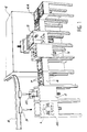
- the system according to the invention is shown in its application for supplying at least one work station 6 which consists of a machine confined in an ultra clean environment.
- the system according to the invention stores and transports flat objects 1 such as extra-flat boxes. These flat objects are stored in series and are transported to be shipped one after the other to work station 6.
- these flat objects 1 are extra-flat boxes containing silicon wafers.
- the latter are treated in a sealed work station 6, that is to say that the silicon wafers are confined in a special atmosphere.
- the extra-flat boxes 1 are waterproof.
- the system according to the invention therefore comprises storage means, means of transport and means of distributing the boxes 1.
- the transport means consist of a plurality of displacement modules 4.
- the distribution means consist of as many distribution modules 5 as there are work stations 6 to be served.
- the storage means consist of storage modules 2 which can accommodate a portable rack 20 for storing boxes 1.
- All these elements constitute a bidirectional conveyor, that is to say capable of transporting the boxes 1 in two opposite directions.
- these different elements are placed against each other so as to constitute a continuous chain of which each element is a link.
- each of these elements have transport rollers 7 placed in two different horizontal planes, parallel to each other so as to constitute two continuous rolling tracks. The distance between each roller 7 is of course less than the length or the width of the boxes 1 transported. In this way, each box 1 can be transported from one module to another while following a continuous track.
- the continuous chain can include changes of direction if the adjacent modules are placed on non-opposite sides.
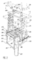
- the storage modules 2 of Figure 1 constituting the storage means can be made as follows.
- the external envelope of the structure of the storage module has been removed.
- a portable rack 20 intended to support a determined number of flat boxes 1 by means of shelves 22 parallel to each other.
- This portable rack 20 is part of the system, but also constitutes an independent element, in the sense that it can be moved and used outside the system. It consists of a portal structure 21, the shelves 22 being placed on the vertical uprights of this structure 21 of the portable rack 20.
- a handling handle 24 can be provided on the upper part 29 of the structure 21.
- the base 23 of this structure 21 has a central part 28 narrower than the ends of this base 23.
- the recesses formed by this narrow central part 28 of the base 23 make it possible to create a space in which the rollers 7 can be vertically translated. this storage module.
- each storage module having to comprise rollers 7 making it possible to move the boxes 1 horizontally, a U-shaped frame 30 is provided, whether viewed from the front or from the side.
- this chassis 30 comprises a flat base 31 on which two to two four vertical uprights 32 are fixed. They are spaced two by two to allow the mounting of parallel rollers 7 between two uprights 32 in a first direction. These rollers 7 are mounted horizontal and rotating between two uprights 32.
- two uprights 32 are also spaced from each other by a space 33 whose width is greater than the width of the central part 28 of the base 23 of the portable rack 20.
- rollers 7 can be mounted at the height of any shelving 22 of the portable rack 20.
- any flat box 1 placed in a rack 22 can be reached by the rollers 7, and raised by the latter, as soon as there are no other boxes below it.
- the two rollers 7 are driven in rotation by means of a motor 34 placed on the corresponding upright 32, driving by a drive belt 35 drive wheels 36 integral in rotation with the rollers 7.
- the portable rack 20 is therefore mobile, thanks to the handling handle 24 and can be detached from the rest of the storage module. Likewise, this portable rack 20 can be placed on a part of the rest of the storage module constituted by a plate 25B placed at the top 25A of a piston 25. The latter is itself slidably mounted inside a piston 26 vertical hollow integral with the base 31 of the chassis 30.
- the handling handle 24 may include control means 24A for locking and locking such a means of fixing the portable rack 20 to the piston 25.
- the hollow piston 26 is slidably mounted inside a cylinder 27.
- the latter is fixed in the structure of the storage module. So at the both the portable rack 20 and the chassis 30 are movable in translation relative to each other but also relative to the storage module in which they are placed. Therefore, the rollers 7 can be placed at the level of the rollers of the two tracks of the two adjacent modules to constitute the intermediate rollers for a track, between the two adjacent modules. Similarly, the flat boxes 1 placed in the shelves 22 of the portable rack 20 can all be lowered onto the rollers 7 when they are placed at the level of the two tracks.
- the lowest flat box 1 in the shelves 22 of the portable rack 20 can always be placed on the rollers 7 and be dispatched on one of the two superimposed tracks.
- a locking and unlocking device 60 of the object stored in the corresponding shelving can be placed outside the structure 21, one below the other. They can be of the electromechanical or electromagnetic type. They can be controlled by central control and management means of the system via a socket 61, placed for example on the base 28 of the portable rack 20 and which can be connected to a corresponding socket of the central control system. It is thus possible to order the release or the locking of one of the objects stored on the shelves of the portable rack 20.
- a main structure 40 parallelepiped includes the operational elements of this displacement module.
- the latter mainly comprises, at the level of the two tracks, two sets of rollers 7, parallel and mounted to rotate about a horizontal axis between the branches 41 of a horizontal H 42 platform. Since there are two superimposed tracks, two horizontal and parallel platforms 42 are used, integral with one another by vertical uprights 43. This thus gives two stages of rollers 7 corresponding to the two levels of the two conveyor tracks made up of these displacement modules, storage modules and distribution modules.
- rollers 7 of a stage are driven by a motor 44, by means of a transmission belt 45 and a drive wheel 46 placed at the end of each shaft 47 around which is mounted rotating a roller 7.
- the motor 44 drives either one of the drive wheels 46, or directly the drive belt 45.
- Two motors 44 are shown, a single motor which can be envisaged per displacement module.
- Figure 1 shows on its right a displacement module 4A constituting a change of direction of 90 ° for the two tracks of the conveyor.
- each displacement module comprises a vertical rotation shaft 48, integral with the H-shaped structure consisting of the uprights 43 and the platforms 42 and mounted to rotate in the structure 40 of the displacement module.
- the set of rollers 7 of the two levels can be placed in all directions, in particular, directions perpendicular to each other to constitute a change of direction of 90 °.
- FIG. 4 represents in section a distribution module of the system according to the invention which comprises also a stage of rollers 7 which can be placed at the level of the two tracks of the conveyor.
- a distribution module comprises an external structure 50 inside which is vertically movable an H 52 base supporting two sets of two rollers 7. The latter are mounted to rotate horizontally between the branches 53 of the H 52 base. L the assembly is completed by a motor 54 driving in rotation an assembly consisting of a belt 55 and drive wheels 56 each placed at the end of a shaft integral in rotation with a roller 7.
- This assembly is mounted vertically movable by means of a hollow piston not shown mounted itself sliding inside a cylinder 57. Inside this latter, there is also mounted sliding sliding a piston 55 at the end 55A of which is fixed a plate distribution form 51.
- the distribution platform 51 and the base 52 are mounted movable in translation in a manner similar to the portable rack 20 and the chassis 30 of a storage module.
- the piston 55 and the platform 51 constitute an elevator for flat objects.
- rollers 7 can ensure the continuity of the two tracks of the conveyor.
- the distribution platform 51 is mounted by lifting the box 1 in question to hoist it up to H level at which it is taken in charge by external organs.
- the motors and the pistons are controlled by means of control and management of the storage, transport and distribution of the flat boxes 1. It is thus possible to manage the storage and distribution to different work stations 6 of a large number of flat boxes 1 by means of the system according to the invention.
- Any storage module 2 can be placed between displacement modules 4 and distribution modules 5 to constitute a buffer storage between two stages of treatment or transport of the boxes. It is thus possible to build any conveying route inside a workshop between different work stations 6.
Landscapes
- Warehouses Or Storage Devices (AREA)
- Container, Conveyance, Adherence, Positioning, Of Wafer (AREA)
Applications Claiming Priority (2)
| Application Number | Priority Date | Filing Date | Title |
|---|---|---|---|
| FR9212424 | 1992-10-16 | ||
| FR9212424A FR2697004B1 (fr) | 1992-10-16 | 1992-10-16 | Système de stockage et de transport d'objets plats tels que des boîtes extra-plates et son ratelier portatif. |
Publications (2)
| Publication Number | Publication Date |
|---|---|
| EP0593367A1 true EP0593367A1 (de) | 1994-04-20 |
| EP0593367B1 EP0593367B1 (de) | 1999-01-07 |
Family
ID=9434624
Family Applications (1)
| Application Number | Title | Priority Date | Filing Date |
|---|---|---|---|
| EP93402534A Expired - Lifetime EP0593367B1 (de) | 1992-10-16 | 1993-10-14 | System zum Transportieren und Speichern von flachen Gegenständen wie extra-flachen Dosen und tragbares Lagergestell dafür |
Country Status (6)
| Country | Link |
|---|---|
| US (1) | US5501564A (de) |
| EP (1) | EP0593367B1 (de) |
| JP (1) | JP3509905B2 (de) |
| KR (1) | KR100304071B1 (de) |
| DE (1) | DE69322922T2 (de) |
| FR (1) | FR2697004B1 (de) |
Cited By (2)
| Publication number | Priority date | Publication date | Assignee | Title |
|---|---|---|---|---|
| EP1685598A4 (de) * | 2003-10-30 | 2011-01-12 | Murata Machinery Ltd | Automatisiertes materialhandhabungssystem |
| CN110104493A (zh) * | 2019-05-15 | 2019-08-09 | 贵州西牛王印务有限公司 | 一种高速包装药业用方便输送的药盒印刷设备 |
Families Citing this family (19)
| Publication number | Priority date | Publication date | Assignee | Title |
|---|---|---|---|---|
| DE4411412C1 (de) * | 1994-03-31 | 1995-09-07 | Riedhammer Gmbh Co Kg | Vorrichtung zum Be- und Entladen eines Brenntischaufbaus mit Brenngut |
| US5588791A (en) * | 1995-08-10 | 1996-12-31 | Intelmatec Corporation | Apparatus for sequentially delivering articles contained in cassettes |
| FR2747112B1 (fr) * | 1996-04-03 | 1998-05-07 | Commissariat Energie Atomique | Dispositif de transport d'objets plats et procede de transfert de ces objets entre ledit dispositif et une machine de traitement |
| JP3360001B2 (ja) * | 1996-10-30 | 2002-12-24 | 芝浦メカトロニクス株式会社 | 処理装置 |
| US6537010B2 (en) | 1999-07-07 | 2003-03-25 | Amtech Systems, Incorporated | Wafer boat support and method for twin tower wafer boat loader |
| US6352399B1 (en) | 1999-07-07 | 2002-03-05 | Amtech Systems, Inc. | Twin tower wafer boat loading system and method |
| JP3915415B2 (ja) * | 2001-03-02 | 2007-05-16 | 株式会社ダイフク | 板状体搬送装置 |
| CH695494A5 (de) * | 2002-05-28 | 2006-06-15 | Rotzinger Ag | Kettenspeicher sowie Verfahren zu dessen Entladung. |
| US6817821B2 (en) * | 2002-10-21 | 2004-11-16 | Robert D. Henderson | Wafer handling for a reflow tool |
| TWI256938B (en) * | 2004-07-26 | 2006-06-21 | Au Optronics Corp | Glass substrate distribute system and method |
| US7497317B2 (en) * | 2005-11-02 | 2009-03-03 | Chunghwa Picture Tubes, Ltd. | Apparatus for conveying and raising objects |
| US7798758B2 (en) * | 2005-11-07 | 2010-09-21 | Brooks Automation, Inc. | Reduced capacity carrier, transport, load port, buffer system |
| US8272827B2 (en) * | 2005-11-07 | 2012-09-25 | Bufano Michael L | Reduced capacity carrier, transport, load port, buffer system |
| FR2902235B1 (fr) * | 2006-06-09 | 2008-10-31 | Alcatel Sa | Dispositif de transport, de stockage et de transfert de substrats |
| US20080121543A1 (en) * | 2006-08-08 | 2008-05-29 | Kamile Bartlett | Coordination System & Method |
| DE102006054846C5 (de) * | 2006-11-20 | 2012-05-03 | Permatecs Gmbh | Produktionsanlage zur Herstellung von Solarzellen im Inline-Verfahren, sowie Verfahren zur Integration eines Batch-Prozesses in eine mehrspurige Inline-Produktionsanlage für Solarzellen |
| US20090067957A1 (en) * | 2007-09-06 | 2009-03-12 | Mitsuhiro Ando | Transport system with buffering |
| EP2445003A1 (de) * | 2010-10-25 | 2012-04-25 | Applied Materials, Inc. | Vorrichtung zur Bereitstellung eines Drehträgermagazins und Bedienungsverfahren dafür |
| CN112960321A (zh) * | 2021-02-19 | 2021-06-15 | 安徽正盟建设工程有限公司 | 一种用于轻轨施工的轨道传输设备 |
Citations (3)
| Publication number | Priority date | Publication date | Assignee | Title |
|---|---|---|---|---|
| EP0115357A2 (de) * | 1980-10-14 | 1984-08-08 | Maurice Prodel | Montage- und/oder Bearbeitungsanlage für Werkstücke, welche durch laufende und arretierbare Werkstückträger getragen werden |
| DE3539957A1 (de) * | 1985-11-11 | 1987-06-19 | Fraunhofer Ges Forschung | Magazinbe- und entladevorrichtung fuer unbestueckte und bestueckte platinen zur versorgung eines bestueckungsautomaten |
| EP0302542A1 (de) * | 1987-07-14 | 1989-02-08 | Koninklijke Philips Electronics N.V. | Vorrichtung zum Ein- und Ausführen von Trägern in einem Positionierungsgerät und Wähleinrichtung zum Anwenden in einer derartigen Vorrichtung |
Family Cites Families (9)
| Publication number | Priority date | Publication date | Assignee | Title |
|---|---|---|---|---|
| US4153164A (en) * | 1978-06-13 | 1979-05-08 | Kasper Instruments, Inc. | Carrier for semiconductive wafers |
| US4299518A (en) * | 1980-03-03 | 1981-11-10 | Texas Instruments Incorporated | Manufacturing work station |
| US4636128A (en) * | 1984-08-30 | 1987-01-13 | Texas Instruments Incorporated | Semiconductor slice cassette transport unit |
| US4759681A (en) * | 1985-01-22 | 1988-07-26 | Nissin Electric Co. Ltd. | End station for an ion implantation apparatus |
| JPS61188331A (ja) * | 1985-02-15 | 1986-08-22 | Nippon Texas Instr Kk | 物体取出装置 |
| JPS6299046A (ja) * | 1985-10-22 | 1987-05-08 | Nec Corp | ワ−クの供給収納装置 |
| US5102291A (en) * | 1987-05-21 | 1992-04-07 | Hine Design Inc. | Method for transporting silicon wafers |
| US4872554A (en) * | 1987-07-02 | 1989-10-10 | Fluoroware, Inc. | Reinforced carrier with embedded rigid insert |
| JPH0770861B2 (ja) * | 1988-05-18 | 1995-07-31 | 三洋電機株式会社 | 基板供給及び収納方法 |
-
1992
- 1992-10-16 FR FR9212424A patent/FR2697004B1/fr not_active Expired - Fee Related
-
1993
- 1993-10-01 US US08/131,211 patent/US5501564A/en not_active Expired - Lifetime
- 1993-10-14 EP EP93402534A patent/EP0593367B1/de not_active Expired - Lifetime
- 1993-10-14 DE DE69322922T patent/DE69322922T2/de not_active Expired - Fee Related
- 1993-10-15 KR KR1019930021477A patent/KR100304071B1/ko not_active Expired - Fee Related
- 1993-10-15 JP JP25866093A patent/JP3509905B2/ja not_active Expired - Fee Related
Patent Citations (3)
| Publication number | Priority date | Publication date | Assignee | Title |
|---|---|---|---|---|
| EP0115357A2 (de) * | 1980-10-14 | 1984-08-08 | Maurice Prodel | Montage- und/oder Bearbeitungsanlage für Werkstücke, welche durch laufende und arretierbare Werkstückträger getragen werden |
| DE3539957A1 (de) * | 1985-11-11 | 1987-06-19 | Fraunhofer Ges Forschung | Magazinbe- und entladevorrichtung fuer unbestueckte und bestueckte platinen zur versorgung eines bestueckungsautomaten |
| EP0302542A1 (de) * | 1987-07-14 | 1989-02-08 | Koninklijke Philips Electronics N.V. | Vorrichtung zum Ein- und Ausführen von Trägern in einem Positionierungsgerät und Wähleinrichtung zum Anwenden in einer derartigen Vorrichtung |
Cited By (3)
| Publication number | Priority date | Publication date | Assignee | Title |
|---|---|---|---|---|
| EP1685598A4 (de) * | 2003-10-30 | 2011-01-12 | Murata Machinery Ltd | Automatisiertes materialhandhabungssystem |
| CN110104493A (zh) * | 2019-05-15 | 2019-08-09 | 贵州西牛王印务有限公司 | 一种高速包装药业用方便输送的药盒印刷设备 |
| CN110104493B (zh) * | 2019-05-15 | 2024-05-10 | 贵州西牛王印务有限公司 | 一种高速包装药业用方便输送的药盒印刷设备 |
Also Published As
| Publication number | Publication date |
|---|---|
| JPH06263211A (ja) | 1994-09-20 |
| FR2697004A1 (fr) | 1994-04-22 |
| FR2697004B1 (fr) | 1994-11-18 |
| US5501564A (en) | 1996-03-26 |
| DE69322922T2 (de) | 1999-07-29 |
| JP3509905B2 (ja) | 2004-03-22 |
| KR100304071B1 (ko) | 2001-12-28 |
| EP0593367B1 (de) | 1999-01-07 |
| DE69322922D1 (de) | 1999-02-18 |
| KR940009037A (ko) | 1994-05-16 |
Similar Documents
| Publication | Publication Date | Title |
|---|---|---|
| EP0593367B1 (de) | System zum Transportieren und Speichern von flachen Gegenständen wie extra-flachen Dosen und tragbares Lagergestell dafür | |
| EP0572650B1 (de) | Automatisiertes lager und wagen zur einlagerung und entnahme von produkten in den speicherbereichen | |
| EP1561236B1 (de) | Transport- und lagerungssystem für halbleiterscheibenbehälter | |
| FR2682670A1 (fr) | Dispositif d'acheminement et de stockage dans un batiment a blocs et etages multiples, commande par ordinateur, pour le transfert de materiels a un autre bloc ou a un autre etage. | |
| FR2559139A1 (fr) | Chariot, en particulier pour machines de triage, avec plateau inclinable actionne independamment | |
| EP0437146A1 (de) | Vorrichtung zum Lagern flacher Gegenstände in Regalen mit Zwischenlagerung | |
| JP2003072917A (ja) | 荷保管設備 | |
| WO2008152245A2 (fr) | Navette avec plateau pour entrepot de stockage et /ou de preparation logistique | |
| FR2576583A1 (fr) | Chariot a plateau inclinable, notamment pour machines de triage | |
| US20040191032A1 (en) | Bi-directional arm and storage system | |
| FR3007310A1 (fr) | Unite de production de produits manufactures comprenant un magasin automotique apte a etre associe a l execution de taches d un processus de fabrication | |
| JP2003072905A (ja) | 荷取り扱い設備 | |
| EP1812325B1 (de) | Verfahren und anlage zur automatischen gepäckhandhabung | |
| EP0736470B1 (de) | Uebergabeanlage von Behältern für durch Schwerkraft fliessende Produkte | |
| FR2623891A1 (fr) | Installation pour briqueter la paroi interieure d'une enceinte | |
| FR2593488A1 (fr) | Transelevateur pour rayon, constitue par un engin de levage | |
| EP1086910A1 (de) | Automatisiertes Kompaktlagerregal | |
| FR3151580A1 (fr) | Véhicule à guidage automatique et système de rack convenant pour un tel véhicule. | |
| EP2417030A1 (de) | Lagerungsvorrichtung und verbessertes transportsystem | |
| FR2665150A1 (fr) | Dispositif pour le chargement ou le dechargement de caissettes. | |
| EP4032747A1 (de) | Mobiler warentransportbehälter und mit einem solchen behälter ausgestattetes fahrzeug | |
| WO2021176184A9 (fr) | Système et procédé de transfert de contenants dans un entrepôt de stockage | |
| BE1003960A7 (fr) | Procede et ensemble transporteur pour l'assemblage d'elements sur une base. | |
| JPH08340043A (ja) | ウエハ保管装置 | |
| FR1278789A (fr) | Perfectionnements aux installations pour le garage automatique des véhicules et opérations analogues |
Legal Events
| Date | Code | Title | Description |
|---|---|---|---|
| PUAI | Public reference made under article 153(3) epc to a published international application that has entered the european phase |
Free format text: ORIGINAL CODE: 0009012 |
|
| AK | Designated contracting states |
Kind code of ref document: A1 Designated state(s): DE GB IT |
|
| 17P | Request for examination filed |
Effective date: 19940924 |
|
| 17Q | First examination report despatched |
Effective date: 19961016 |
|
| GRAG | Despatch of communication of intention to grant |
Free format text: ORIGINAL CODE: EPIDOS AGRA |
|
| GRAG | Despatch of communication of intention to grant |
Free format text: ORIGINAL CODE: EPIDOS AGRA |
|
| GRAH | Despatch of communication of intention to grant a patent |
Free format text: ORIGINAL CODE: EPIDOS IGRA |
|
| GRAH | Despatch of communication of intention to grant a patent |
Free format text: ORIGINAL CODE: EPIDOS IGRA |
|
| GRAA | (expected) grant |
Free format text: ORIGINAL CODE: 0009210 |
|
| AK | Designated contracting states |
Kind code of ref document: B1 Designated state(s): DE GB IT |
|
| REF | Corresponds to: |
Ref document number: 69322922 Country of ref document: DE Date of ref document: 19990218 |
|
| ITF | It: translation for a ep patent filed | ||
| GBT | Gb: translation of ep patent filed (gb section 77(6)(a)/1977) |
Effective date: 19990310 |
|
| PLBE | No opposition filed within time limit |
Free format text: ORIGINAL CODE: 0009261 |
|
| STAA | Information on the status of an ep patent application or granted ep patent |
Free format text: STATUS: NO OPPOSITION FILED WITHIN TIME LIMIT |
|
| 26N | No opposition filed | ||
| REG | Reference to a national code |
Ref country code: GB Ref legal event code: IF02 |
|
| PGFP | Annual fee paid to national office [announced via postgrant information from national office to epo] |
Ref country code: IT Payment date: 20071026 Year of fee payment: 15 |
|
| PGFP | Annual fee paid to national office [announced via postgrant information from national office to epo] |
Ref country code: GB Payment date: 20071010 Year of fee payment: 15 |
|
| PGFP | Annual fee paid to national office [announced via postgrant information from national office to epo] |
Ref country code: DE Payment date: 20081024 Year of fee payment: 16 |
|
| GBPC | Gb: european patent ceased through non-payment of renewal fee |
Effective date: 20081014 |
|
| PG25 | Lapsed in a contracting state [announced via postgrant information from national office to epo] |
Ref country code: IT Free format text: LAPSE BECAUSE OF NON-PAYMENT OF DUE FEES Effective date: 20081014 |
|
| PG25 | Lapsed in a contracting state [announced via postgrant information from national office to epo] |
Ref country code: GB Free format text: LAPSE BECAUSE OF NON-PAYMENT OF DUE FEES Effective date: 20081014 |
|
| PG25 | Lapsed in a contracting state [announced via postgrant information from national office to epo] |
Ref country code: DE Free format text: LAPSE BECAUSE OF NON-PAYMENT OF DUE FEES Effective date: 20100501 |