EP0593588B1 - Schutzeinrichtung für schaltung - Google Patents
Schutzeinrichtung für schaltung Download PDFInfo
- Publication number
- EP0593588B1 EP0593588B1 EP92914575A EP92914575A EP0593588B1 EP 0593588 B1 EP0593588 B1 EP 0593588B1 EP 92914575 A EP92914575 A EP 92914575A EP 92914575 A EP92914575 A EP 92914575A EP 0593588 B1 EP0593588 B1 EP 0593588B1
- Authority
- EP
- European Patent Office
- Prior art keywords
- arrangement
- fet
- line
- current
- gate
- Prior art date
- Legal status (The legal status is an assumption and is not a legal conclusion. Google has not performed a legal analysis and makes no representation as to the accuracy of the status listed.)
- Expired - Lifetime
Links
Images

Classifications
-
- H—ELECTRICITY
- H02—GENERATION; CONVERSION OR DISTRIBUTION OF ELECTRIC POWER
- H02H—EMERGENCY PROTECTIVE CIRCUIT ARRANGEMENTS
- H02H3/00—Emergency protective circuit arrangements for automatic disconnection directly responsive to an undesired change from normal electric working condition with or without subsequent reconnection ; integrated protection
- H02H3/08—Emergency protective circuit arrangements for automatic disconnection directly responsive to an undesired change from normal electric working condition with or without subsequent reconnection ; integrated protection responsive to excess current
- H02H3/087—Emergency protective circuit arrangements for automatic disconnection directly responsive to an undesired change from normal electric working condition with or without subsequent reconnection ; integrated protection responsive to excess current for DC applications
-
- H—ELECTRICITY
- H02—GENERATION; CONVERSION OR DISTRIBUTION OF ELECTRIC POWER
- H02H—EMERGENCY PROTECTIVE CIRCUIT ARRANGEMENTS
- H02H3/00—Emergency protective circuit arrangements for automatic disconnection directly responsive to an undesired change from normal electric working condition with or without subsequent reconnection ; integrated protection
- H02H3/08—Emergency protective circuit arrangements for automatic disconnection directly responsive to an undesired change from normal electric working condition with or without subsequent reconnection ; integrated protection responsive to excess current
-
- H—ELECTRICITY
- H02—GENERATION; CONVERSION OR DISTRIBUTION OF ELECTRIC POWER
- H02H—EMERGENCY PROTECTIVE CIRCUIT ARRANGEMENTS
- H02H9/00—Emergency protective circuit arrangements for limiting excess current or voltage without disconnection
- H02H9/02—Emergency protective circuit arrangements for limiting excess current or voltage without disconnection responsive to excess current
- H02H9/025—Current limitation using field effect transistors
-
- H—ELECTRICITY
- H03—ELECTRONIC CIRCUITRY
- H03K—PULSE TECHNIQUE
- H03K17/00—Electronic switching or gating, i.e. not by contact-making and –breaking
- H03K17/08—Modifications for protecting switching circuit against overcurrent or overvoltage
- H03K17/082—Modifications for protecting switching circuit against overcurrent or overvoltage by feedback from the output to the control circuit
- H03K17/0822—Modifications for protecting switching circuit against overcurrent or overvoltage by feedback from the output to the control circuit in field-effect transistor switches
-
- H—ELECTRICITY
- H03—ELECTRONIC CIRCUITRY
- H03K—PULSE TECHNIQUE
- H03K17/00—Electronic switching or gating, i.e. not by contact-making and –breaking
- H03K17/51—Electronic switching or gating, i.e. not by contact-making and –breaking characterised by the components used
- H03K17/78—Electronic switching or gating, i.e. not by contact-making and –breaking characterised by the components used using opto-electronic devices, i.e. light-emitting and photoelectric devices electrically- or optically-coupled
- H03K17/785—Electronic switching or gating, i.e. not by contact-making and –breaking characterised by the components used using opto-electronic devices, i.e. light-emitting and photoelectric devices electrically- or optically-coupled controlling field-effect transistor switches
Definitions
- the invention has the advantage that, because the series connected FET is normally in the on state there is no initial voltage drop across the arrangement before it becomes conductive so that the arrangement can be substantially linear.
- the arrangement according to the invention exhibits a "foldback" characteristic , that is to say, one in which the current that passes through the arrangement increases with increasing voltage difference across it until a certain voltage, referred to as the threshold voltage, is reached whereupon the current through the device decreases to a lower value.
- the ratio of the maximum leakage current of the device in its off state to the maximum current of the device in its on state (trip current) is not more than 0.5, more preferably not more than 0.1 and especially not more than 0.01.
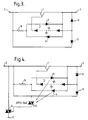
- FIG. 2 shows a modification of the circuit of Figure 1 which is suitable for use in an a.c. circuit.
- a JFET 1 is still connected directly in the line of the circuit between the terminals 2 and 3, but the negative voltage generator 4 is located within a rectifying diode bridge that is formed from diodes 5 and that is connected across the JFET.
- the JFET 1 will pass current in either direction in normal operation while its gate is held below the threshold voltage of the JFET, and a rectified version of the signal voltage across the JFET is fed into its gate by the negative voltage generator.
- the gate bias will increase so as to switch the JFET 1 OFF irrespective of the polarity of the overcurrent.
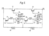
- both FETs 51 and 52 switch off at the same time in order that the voltage drop is evenly distributed over them and the voltage rating of each of the transistors is not exceeded.
- the node between the negative voltage generators 53 and 54 is held at a voltage mid way between the voltages on either side of the two FETs 51 and 52 by means of a voltage divider formed by resistors 59 and 60.
Landscapes
- Engineering & Computer Science (AREA)
- Power Engineering (AREA)
- Amplifiers (AREA)
- Emergency Protection Circuit Devices (AREA)
- Electronic Switches (AREA)
- Air Bags (AREA)
- Control Of Motors That Do Not Use Commutators (AREA)
- Dc-Dc Converters (AREA)
- Direct Current Feeding And Distribution (AREA)
- Protection Of Static Devices (AREA)
Claims (12)
- Anordnung, die eine Rückregelungs-Charakteristik zeigt und dazu bestimmt ist, in Reihe in eine Leitung einer elektrischen Schaltung geschaltet zu werden, um die Schaltung vor einem Überstrom zu schützen, wobei die Anordnung einen Verarmungstyp-FET (1), der den Leitungsstrom schaltet, und eine Steuereinrichtung (4) aufweist, die parallel zu einem Widerstand in der Leitung (2, 3) geschaltet ist und den Gate-Anschluß des FET (1) in Abhängigkeit von der Spannungsdifferenz über dem Widerstand vorspannt, um den FET auszuschalten, wenn die Anordnung einem Überstrom in der Leitung ausgesetzt ist, wobei die Anordnung eine Anordnung mit zwei Anschlüssen oder eine solche ist, bei der ein dritter Anschluß einschaltet, wenn ein Überstrom auftritt, um den Strom im Nebenschluß durch eine mit der Schaltung verbundene Last zu leiten oder um den Strom im Nebenschluß zu einem Masseanschluß zu leiten.
- Anordnung nach Anspruch 1,
wobei die Steuereinrichtung den Gate-Anschluß in Abhängigkeit von einem Spannungsabfall, der über dem FET auftritt, vorspannt. - Anordnung nach Anspruch 2,
die außer dem FET keine in die Leitung geschalteten ohmschen Komponenten aufweist. - Anordnung nach einem der Ansprüche 1 bis 3,
wobei die den Gate-Anschluß vorspannende Steuereinrichtung ein negativer Spannungsgenerator (4) ist. - Anordnung nach einem der Ansprüche 1 bis 3,
wobei die den Gate-Anschluß vorspannende Steuereinrichtung eine opto-elektronische Kopplungsanordnung (8, 9, 11) aufweist. - Anordnung nach Anspruch 5,
wobei die opto-elektronische Kopplungsanordnung eine Lichtquelle (8, 9) aufweist, die von dem Spannungsabfall in der Leitung gespeist wird und die mit einer Photovoltaik-Komponente (11), die mit dem Gate-Anschluß des FET verbunden ist, optisch gekoppelt ist. - Anordnung nach einem der Ansprüche 1 bis 6,
zum Betrieb in einer Wechselstromleitung, wobei die Steuereinrichtung mit der Leitung über eine Gleichrichterbrücke (5, 5, 5, 5) verbunden ist. - Anordnung nach einem der Ansprüche 1 bis 7,
die einen maximalen Leckstrom hat, der nicht größer als der halbe Wert des Auslösestroms ist. - Anordnung nach Anspruch 8,
wobei der maximale Leckstrom nicht mehr als das 0,1fache des Auslösestroms ist. - Anordnung nach einem der Ansprüche 1 bis 9, die eine Anordnung mit drei Anschlüssen ist.
- Anordnung nach Anspruch 10,
die einer Versorgungsleitung der Schaltung keine Leistung entnimmt. - Anordnung nach Anspruch 5 oder Anspruch 6,
die eine Einrichtung mit drei Anschlüssen ist, bei der der dritte Anschluß mit der Steuereinrichtung optisch gekoppelt ist.
Applications Claiming Priority (3)
| Application Number | Priority Date | Filing Date | Title |
|---|---|---|---|
| GB9114717 | 1991-07-08 | ||
| GB919114717A GB9114717D0 (en) | 1991-07-08 | 1991-07-08 | Circuit protection arrangement |
| PCT/GB1992/001237 WO1993001639A1 (en) | 1991-07-08 | 1992-07-08 | Circuit protection arrangement |
Publications (2)
| Publication Number | Publication Date |
|---|---|
| EP0593588A1 EP0593588A1 (de) | 1994-04-27 |
| EP0593588B1 true EP0593588B1 (de) | 1997-03-26 |
Family
ID=10698005
Family Applications (1)
| Application Number | Title | Priority Date | Filing Date |
|---|---|---|---|
| EP92914575A Expired - Lifetime EP0593588B1 (de) | 1991-07-08 | 1992-07-08 | Schutzeinrichtung für schaltung |
Country Status (14)
| Country | Link |
|---|---|
| EP (1) | EP0593588B1 (de) |
| JP (1) | JPH06508980A (de) |
| KR (1) | KR940701595A (de) |
| AT (1) | ATE150910T1 (de) |
| AU (1) | AU665957B2 (de) |
| BR (1) | BR9206251A (de) |
| CA (1) | CA2111966A1 (de) |
| DE (1) | DE69218602T2 (de) |
| ES (1) | ES2101107T3 (de) |
| FI (1) | FI940078A7 (de) |
| GB (1) | GB9114717D0 (de) |
| NO (1) | NO308757B1 (de) |
| NZ (1) | NZ243474A (de) |
| WO (1) | WO1993001639A1 (de) |
Cited By (2)
| Publication number | Priority date | Publication date | Assignee | Title |
|---|---|---|---|---|
| US10205313B2 (en) | 2015-07-24 | 2019-02-12 | Symptote Technologies, LLC | Two-transistor devices for protecting circuits from sustained overcurrent |
| US10770883B2 (en) | 2015-09-21 | 2020-09-08 | Sympote Technologies LLC | One-transistor devices for protecting circuits and autocatalytic voltage conversion therefor |
Families Citing this family (9)
| Publication number | Priority date | Publication date | Assignee | Title |
|---|---|---|---|---|
| TW264598B (de) * | 1992-07-01 | 1995-12-01 | Ray Chem Ltd | |
| GB9213992D0 (en) * | 1992-07-01 | 1992-08-12 | Raychem Ltd | Remotely actuated switch and protection circuit |
| GB9223770D0 (en) * | 1992-11-12 | 1992-12-23 | Raychem Ltd | Communication channel testing arrangement |
| DE69333367T2 (de) * | 1993-02-10 | 2004-09-02 | Line Electronics Corp., Tatsuno | Überstromschutzschaltung und halbleitervorrichtung |
| GB9820132D0 (en) | 1998-09-16 | 1998-11-11 | Raychem Ltd | Battery over-discharge protection |
| US6614881B1 (en) | 2000-10-17 | 2003-09-02 | Tyco Electronics Corporation | Remotely operable telecommunications conductor test circuit and method for using the same |
| US7768761B2 (en) | 2004-11-12 | 2010-08-03 | Bourns, Inc. | Surge protection device |
| US8289667B2 (en) | 2008-04-16 | 2012-10-16 | Bourns, Inc. | Current limiting surge protection device |
| DE102015014588B4 (de) * | 2015-11-12 | 2025-07-10 | Tesat-Spacecom Gmbh & Co. Kg | Vorrichtung zum Begrenzen der Spannung eines Verbrauchers |
Citations (1)
| Publication number | Priority date | Publication date | Assignee | Title |
|---|---|---|---|---|
| EP0446724A2 (de) * | 1990-03-15 | 1991-09-18 | Ixys Corporation | Verfahren und Vorrichtung zur Strombegrenzung |
Family Cites Families (6)
| Publication number | Priority date | Publication date | Assignee | Title |
|---|---|---|---|---|
| US4110809A (en) * | 1976-12-30 | 1978-08-29 | Lockheed Aircraft Corporation | Solid state power controller with low level signal control |
| DE2811696C3 (de) * | 1978-03-17 | 1980-09-11 | Schmid Fernmeldetechnik, Zuerich (Schweiz) | Elektronischer Koppelpunkt zum Durchschalten von Fernsprech- oder Datensignalen in einer symmetrischen Verteil- und Koppelanordnung |
| US4603234A (en) * | 1983-04-04 | 1986-07-29 | Gte Lenkurt Incorporated | Switching circuit including current limiting and initializing signal isolation |
| US4533970A (en) * | 1983-06-27 | 1985-08-06 | Motorola, Inc. | Series current limiter |
| DE3725390A1 (de) * | 1987-07-31 | 1989-02-09 | Wickmann Werke Gmbh | Schaltsicherung |
| US4835649A (en) * | 1987-12-14 | 1989-05-30 | United Technologies Corporation | Self-latching current limiter |
-
1991
- 1991-07-08 GB GB919114717A patent/GB9114717D0/en active Pending
-
1992
- 1992-07-08 AU AU22441/92A patent/AU665957B2/en not_active Ceased
- 1992-07-08 JP JP5502102A patent/JPH06508980A/ja active Pending
- 1992-07-08 FI FI940078A patent/FI940078A7/fi not_active Application Discontinuation
- 1992-07-08 NZ NZ243474A patent/NZ243474A/en not_active IP Right Cessation
- 1992-07-08 ES ES92914575T patent/ES2101107T3/es not_active Expired - Lifetime
- 1992-07-08 EP EP92914575A patent/EP0593588B1/de not_active Expired - Lifetime
- 1992-07-08 BR BR9206251A patent/BR9206251A/pt not_active Application Discontinuation
- 1992-07-08 KR KR1019930704042A patent/KR940701595A/ko not_active Withdrawn
- 1992-07-08 AT AT92914575T patent/ATE150910T1/de not_active IP Right Cessation
- 1992-07-08 WO PCT/GB1992/001237 patent/WO1993001639A1/en not_active Ceased
- 1992-07-08 DE DE69218602T patent/DE69218602T2/de not_active Expired - Fee Related
- 1992-07-08 CA CA002111966A patent/CA2111966A1/en not_active Abandoned
-
1994
- 1994-01-07 NO NO940063A patent/NO308757B1/no not_active IP Right Cessation
Patent Citations (1)
| Publication number | Priority date | Publication date | Assignee | Title |
|---|---|---|---|---|
| EP0446724A2 (de) * | 1990-03-15 | 1991-09-18 | Ixys Corporation | Verfahren und Vorrichtung zur Strombegrenzung |
Cited By (6)
| Publication number | Priority date | Publication date | Assignee | Title |
|---|---|---|---|---|
| US10205313B2 (en) | 2015-07-24 | 2019-02-12 | Symptote Technologies, LLC | Two-transistor devices for protecting circuits from sustained overcurrent |
| US11031769B2 (en) | 2015-07-24 | 2021-06-08 | Symptote Technologies, LLC | Two-transistor devices for protecting circuits from sustained overcurrent |
| US10770883B2 (en) | 2015-09-21 | 2020-09-08 | Sympote Technologies LLC | One-transistor devices for protecting circuits and autocatalytic voltage conversion therefor |
| US11355916B2 (en) | 2015-09-21 | 2022-06-07 | Symptote Technologies Llc | One-transistor devices for protecting circuits and autocatalytic voltage conversion therefor |
| US11611206B2 (en) | 2015-09-21 | 2023-03-21 | Symptote Technologies Llc | One-transistor devices for protecting circuits and autocatalytic voltage conversion therefor |
| US11962141B2 (en) | 2015-09-21 | 2024-04-16 | Symptote Technologies Llc | One-transistor devices for protecting circuits and autocatalytic voltage conversion therefor |
Also Published As
| Publication number | Publication date |
|---|---|
| DE69218602D1 (de) | 1997-04-30 |
| FI940078A0 (fi) | 1994-01-07 |
| ES2101107T3 (es) | 1997-07-01 |
| CA2111966A1 (en) | 1993-01-21 |
| NO940063D0 (no) | 1994-01-07 |
| WO1993001639A1 (en) | 1993-01-21 |
| JPH06508980A (ja) | 1994-10-06 |
| AU665957B2 (en) | 1996-01-25 |
| AU2244192A (en) | 1993-02-11 |
| NO940063L (no) | 1994-01-07 |
| EP0593588A1 (de) | 1994-04-27 |
| DE69218602T2 (de) | 1997-11-13 |
| KR940701595A (ko) | 1994-05-28 |
| FI940078L (fi) | 1994-01-07 |
| ATE150910T1 (de) | 1997-04-15 |
| BR9206251A (pt) | 1994-12-20 |
| FI940078A7 (fi) | 1994-01-07 |
| NZ243474A (en) | 1995-07-26 |
| GB9114717D0 (en) | 1991-08-28 |
| NO308757B1 (no) | 2000-10-23 |
Similar Documents
| Publication | Publication Date | Title |
|---|---|---|
| US12356728B2 (en) | Protection circuit with a FET device coupled from a protected bus to ground | |
| US4581540A (en) | Current overload protected solid state relay | |
| US5914545A (en) | Switching device with power FET and short-circuit detection | |
| EP0566594B1 (de) | Überstromschutzvorrichtung | |
| CA1122663A (en) | Protection circuit for transistorized switch | |
| EP0593588B1 (de) | Schutzeinrichtung für schaltung | |
| US6067219A (en) | Power cut-off device | |
| JP2664678B2 (ja) | 電源回路 | |
| DE59602580D1 (de) | Schaltungsanordnung zur Begrenzung von Schaltüberspannungen an Leistungshalbleiterschaltern | |
| US5111070A (en) | DC input circuit with controlled leakage current | |
| US5208718A (en) | Protection circuit | |
| US5764088A (en) | Control circuit for an electronic switch, and a switch constituting an application thereof | |
| US7301745B2 (en) | Temperature dependent switching circuit | |
| US5488533A (en) | Methods and apparatus for isolating a power network from a load during an overcurrent condition | |
| GB2238674A (en) | Control circuit for scr ac relay. | |
| US4395637A (en) | Optically toggled latch-free normally off switch | |
| US20250015711A1 (en) | Limiting circuit for use in explosion protection environments | |
| RU2056691C1 (ru) | Устройство для защиты электроустановки (варианты) | |
| US4365281A (en) | Protection circuit for switching transistors serially connected between a D.C. voltage source | |
| SU1517014A1 (ru) | Устройство защиты нагрузки от перенапр жени на выходе стабилизатора | |
| SU845213A1 (ru) | Устройство дл защиты электрическойцЕпи OT пЕРЕгРузКи пО ТОКу иНАпР жЕНию | |
| JPH02223335A (ja) | 保護回路 |
Legal Events
| Date | Code | Title | Description |
|---|---|---|---|
| PUAI | Public reference made under article 153(3) epc to a published international application that has entered the european phase |
Free format text: ORIGINAL CODE: 0009012 |
|
| 17P | Request for examination filed |
Effective date: 19931208 |
|
| AK | Designated contracting states |
Kind code of ref document: A1 Designated state(s): AT BE CH DE DK ES FR GB GR IT LI NL SE |
|
| 17Q | First examination report despatched |
Effective date: 19950303 |
|
| GRAG | Despatch of communication of intention to grant |
Free format text: ORIGINAL CODE: EPIDOS AGRA |
|
| GRAH | Despatch of communication of intention to grant a patent |
Free format text: ORIGINAL CODE: EPIDOS IGRA |
|
| GRAH | Despatch of communication of intention to grant a patent |
Free format text: ORIGINAL CODE: EPIDOS IGRA |
|
| GRAA | (expected) grant |
Free format text: ORIGINAL CODE: 0009210 |
|
| AK | Designated contracting states |
Kind code of ref document: B1 Designated state(s): AT BE CH DE DK ES FR GB GR IT LI NL SE |
|
| PG25 | Lapsed in a contracting state [announced via postgrant information from national office to epo] |
Ref country code: LI Effective date: 19970326 Ref country code: GR Free format text: LAPSE BECAUSE OF FAILURE TO SUBMIT A TRANSLATION OF THE DESCRIPTION OR TO PAY THE FEE WITHIN THE PRESCRIBED TIME-LIMIT Effective date: 19970326 Ref country code: DK Effective date: 19970326 Ref country code: CH Effective date: 19970326 Ref country code: AT Effective date: 19970326 |
|
| REF | Corresponds to: |
Ref document number: 150910 Country of ref document: AT Date of ref document: 19970415 Kind code of ref document: T |
|
| REG | Reference to a national code |
Ref country code: CH Ref legal event code: EP |
|
| REF | Corresponds to: |
Ref document number: 69218602 Country of ref document: DE Date of ref document: 19970430 |
|
| ITF | It: translation for a ep patent filed | ||
| ET | Fr: translation filed | ||
| REG | Reference to a national code |
Ref country code: ES Ref legal event code: FG2A Ref document number: 2101107 Country of ref document: ES Kind code of ref document: T3 |
|
| REG | Reference to a national code |
Ref country code: CH Ref legal event code: PL |
|
| PLBE | No opposition filed within time limit |
Free format text: ORIGINAL CODE: 0009261 |
|
| STAA | Information on the status of an ep patent application or granted ep patent |
Free format text: STATUS: NO OPPOSITION FILED WITHIN TIME LIMIT |
|
| 26N | No opposition filed | ||
| REG | Reference to a national code |
Ref country code: GB Ref legal event code: IF02 |
|
| PGFP | Annual fee paid to national office [announced via postgrant information from national office to epo] |
Ref country code: ES Payment date: 20080728 Year of fee payment: 17 Ref country code: DE Payment date: 20080829 Year of fee payment: 17 |
|
| PGFP | Annual fee paid to national office [announced via postgrant information from national office to epo] |
Ref country code: NL Payment date: 20080724 Year of fee payment: 17 Ref country code: IT Payment date: 20080728 Year of fee payment: 17 Ref country code: FR Payment date: 20080729 Year of fee payment: 17 |
|
| PGFP | Annual fee paid to national office [announced via postgrant information from national office to epo] |
Ref country code: GB Payment date: 20080729 Year of fee payment: 17 |
|
| PGFP | Annual fee paid to national office [announced via postgrant information from national office to epo] |
Ref country code: SE Payment date: 20080729 Year of fee payment: 17 Ref country code: BE Payment date: 20080818 Year of fee payment: 17 |
|
| BERE | Be: lapsed |
Owner name: *RAYCHEM LTD Effective date: 20090731 |
|
| EUG | Se: european patent has lapsed | ||
| GBPC | Gb: european patent ceased through non-payment of renewal fee |
Effective date: 20090708 |
|
| NLV4 | Nl: lapsed or anulled due to non-payment of the annual fee |
Effective date: 20100201 |
|
| REG | Reference to a national code |
Ref country code: FR Ref legal event code: ST Effective date: 20100331 |
|
| PG25 | Lapsed in a contracting state [announced via postgrant information from national office to epo] |
Ref country code: FR Free format text: LAPSE BECAUSE OF NON-PAYMENT OF DUE FEES Effective date: 20090731 |
|
| PG25 | Lapsed in a contracting state [announced via postgrant information from national office to epo] |
Ref country code: GB Free format text: LAPSE BECAUSE OF NON-PAYMENT OF DUE FEES Effective date: 20090708 |
|
| PG25 | Lapsed in a contracting state [announced via postgrant information from national office to epo] |
Ref country code: DE Free format text: LAPSE BECAUSE OF NON-PAYMENT OF DUE FEES Effective date: 20100202 Ref country code: BE Free format text: LAPSE BECAUSE OF NON-PAYMENT OF DUE FEES Effective date: 20090731 |
|
| REG | Reference to a national code |
Ref country code: ES Ref legal event code: FD2A Effective date: 20090709 |
|
| PG25 | Lapsed in a contracting state [announced via postgrant information from national office to epo] |
Ref country code: ES Free format text: LAPSE BECAUSE OF NON-PAYMENT OF DUE FEES Effective date: 20090709 |
|
| PG25 | Lapsed in a contracting state [announced via postgrant information from national office to epo] |
Ref country code: IT Free format text: LAPSE BECAUSE OF NON-PAYMENT OF DUE FEES Effective date: 20090708 |
|
| PG25 | Lapsed in a contracting state [announced via postgrant information from national office to epo] |
Ref country code: SE Free format text: LAPSE BECAUSE OF NON-PAYMENT OF DUE FEES Effective date: 20090709 |
|
| PG25 | Lapsed in a contracting state [announced via postgrant information from national office to epo] |
Ref country code: NL Free format text: LAPSE BECAUSE OF NON-PAYMENT OF DUE FEES Effective date: 20100201 |